
Create successful ePaper yourself
Turn your PDF publications into a flip-book with our unique Google optimized e-Paper software.
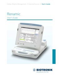
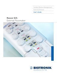
Cardiac Rhythm ManagementExternal DevicesQuick Reference Guide<strong>Renamic</strong>Medical programmer and monitoring device
Active function Patient name Device name and serial numberHeart rateButton for setting the gainof the respective signalButton for enlarging/reducingthe ECG windowDisplay area forstatus messagesTelemetry status in 6 stages(0 bars = 0% up to 5 bars = 100%)ECG monitor(values derived from real-time IEGM)Freeze function(ECG snapshot of the last 60 sec.)Settings for the ECG displayNavigator withnavigation buttonsApplication windowHelp function (accessible fromany application window)Function buttons (depending onthe current application window)ECG windowButton for exiting the follow-upsession. The start screen is displayedand all interrogated data and testresults are stored.Forward/back navigation
3130272621222523242928
1 Touch screen2 Device body3 USB ports4 ECG port5 Slot for expansion module6 Screen release button (right)7 Fixation for carrying strap (right)8 Pen holder9 PGH compartment lid release button10 Printer buttons11 Stylus in pen holder12 Safe program button13 Emergency shock button14 Carrying handle15 Fixation for carrying strap (left)16 Screen release button (left)18 Paper tray for internal printer19 On/off button20 Power cord port and device fuse21 PGH port22 USB slot with Bluetooth USB adapter23 PGH cable and ECG cable24 Cable feedthrough for PGH cable25 On/off LED26 Programming head (PGH)27 PGH compartment lid28 Anti-slip stand29 Gripping tab30 Power cord in power cord storage compartment31 Power cord compartment lid
NavigationAll parameters displayedin bold print can be selected.Other application windows areopened on selection.Summary of the most importantfollow-up data.Change the programmableparameters of the implanted device.Perform tests(e.g. threshold test).Display the signalsrecorded by the implanted device.Open the patient data in the[Parameters] application window.Display all interrogatedimplanted device statistics.Open the list of recently recordedsignals in the [Recordings]application window.Summary of the status ofthe implanted device.Print manager(list of all stored printing data).Open the corresponding test in the[Tests] application window.Adapt the basic settings forindividual configuration.
Switching the device on and offThe on/off button (19) is located on the back left side of the device.To switch on the device:• Press the on/off button (19) once to the pressure point.The on/off LED (25) on the front left side of the device lights up.To switch off the device:• Press the on/off button (19) once to the pressure pointor• Shut down the device via the user interface.On/off button on the deviceNote:If the power supply to <strong>Renamic</strong> is interrupted, the device will require approximately60 seconds to restart once the power supply is reconnected.If the power supply to <strong>Renamic</strong> is not interrupted and the device is switched off using thebutton on the screen or the on/off button on the device (19), then the device will requireapproximately 30 seconds to restart.Button for switching off the device in the user interface.
Freeze function (ECG/IEGM recording)Freeze/Print<strong>Renamic</strong> constantly stores the last 60 seconds of the real-time signals (IEGM, ECG and markers) displayed in the ECG window.The Freeze function can be used to pause the signal display in order to analyze events that have occurred within the last 60 seconds.Key below the ECG area to open the[Freeze] button.Display of the IEGM amplitude (A, RV, LV) at the position ofthe left caliper (1) and the right caliper (2)Keys for precise placement of the caliper lines. The calipers can also be positionedon the ECG display itself (select, hold and drag).(1) (2)Circle function to check constant distances between several eventsButton for printing the displayed recording section. The recording issimultaneously stored as a file in the follow-up data of the print and datamanager tabs with the designation "Freeze".Button for saving as a file in the follow-up data of the print and datamanager tabs with the designation "Freeze".Selection to print or store the entire length of 60 seconds, onlythe window contents, or the section between the caliper lines.
Printing during follow-upThe [Print] button is available in every application window for immediate printing. All datainterrogated and produced during follow-up are automatically stored and can be displayed in thePrint manager tab at any time using the [More] button.List of all stored follow-ups for theimplanted device being interrogated.List of available data foractivated follow-up.The activated follow-up ishighlighted in blue.The current follow-up session isselected by default.Keys for selecting the print profiles.The check boxes for available data areadapted to the respective profile.Check box for selecting or deselectingthe follow-up data to be printed.
Printing and exporting stored dataExportSelect the [Data manager] button on the start screen. All stored follow-up data can be viewed, printed, exported and sorted according to the displayedcolumns. Lines containing the same information in the sorted column are summarized. For example, if the follow-up data is sorted according to the "Patient"column, then all follow-up data for a single patient will be summarized. However, if the "Date" column is selected for sorting, then all follow-up data will besummarized for the same date but with various different patients.Select a column header to sort andsummarize the follow-up data.Edit the patient nameselected with a check box.Use the arrows to expandor collapse the summarizedfollow-up data.Export the selected follow-up data inAdobe PDF format.Data export settings.Export follow-up data that has beenselected using the check boxes.Import follow-up data in<strong>BIOTRONIK</strong> backup format.
Data export settingsSelect the [Data manager] button on the start screen and then [Options] to configure the data export settings. Activate or deactivate the checkboxes to set the format in which the follow-up data will be exported via the available interfaces (USB stick, Bluetooth adapter, serial RS 232 interface).Export to USB stickSelect this function to transmit the export file in<strong>BIOTRONIK</strong> XML format and as a PDF documentwith each transmission.Export to a device connectedvia a Bluetooth adapter(See Preferences for Bluetooth PIN)Backup: Encrypted file format only for importing backupdata on a <strong>BIOTRONIK</strong> <strong>Renamic</strong> or ICS 3000 programmer.<strong>BIOTRONIK</strong>-XML: Open, freely available proprietary exportformat based on the XML standard. An XML file is createdfor each follow-up.When exporting to a USB stick, you canenter a destination directory for the data.The top level of the destination directorymust be the "<strong>BIOTRONIK</strong>" directory."USB stick\<strong>BIOTRONIK</strong>\..."Paceart-XML: Paceart compatible export format.An XML file is created for each follow-up.
PreferencesAdapting the settingsSelect the [Preferences] button in the navigator and then select the desired tab and enter your preferences.[Follow-up] tab: Configures which measurements andtests are performed automatically during follow-up and howthe results are output.[Tests] tab: Sets parameters affecting the test sequenceduring follow-up.[Print] tab: Configures a PCL compatible external printerthat is connected via a USB or Bluetooth adapter, or sets updifferent printing profiles for printing the follow-up data.[System] tab: Sets the time, daylight saving time (DST) or winter time,date, language of the user interface and the help function.[Connectivity] tab: Sets up communication connectionsto other devices.
Settings for initial data export using the Bluetooth adapterThe Bluetooth connection has to be established before <strong>Renamic</strong> can export data via the Bluetooth adapter.The Bluetooth search dialog box appears the first time an export is performed via the Bluetooth adapter.Once the search is finished, <strong>Renamic</strong> displays all devices available for connection.The first time an export is performed, the <strong>Renamic</strong> Bluetooth PIN must be entered into the PC that is to be connected via Bluetooth.The Bluetooth PIN for connecting the <strong>Renamic</strong> is: 1358.The Bluetooth connection only has to be configured once.
Place <strong>Renamic</strong> in the ideal position for SafeSync RF telemetryRF TelemetryVarious factors can impair the quality of the SafeSync RF telemetry connection. The current connection quality (1) is displayed in the programmer’s status bar.This display can be used to determine the optimum position. In doing so, take the delay in the field strength display (1) into consideration.1(2)Proceed as follows if the connection quality is impaired:• Change the position of the programmer or its orientation to the implanted device by slightly rotating ormoving it. When you do this, consider the delay in the field strength display (1) and observe thepreferred direction for SafeSync RF telemetry (2).• Ensure that no objects or persons are located in the path between <strong>Renamic</strong> and the implanted device.• Position <strong>Renamic</strong> as far away as possible from other electrical devices.• Do not place the device to be implanted directly on metal surfaces, as the effectiveness of the antennais significantly reduced in the vicinity of electrically conductive surfaces.(2)Preferred directions (2) for SafeSync RF telemetry
Placing paper in the printer trayPush back the separator flap• Open the printer tray by applying slight pressure from above.• Do not pull the tray all the way out.• Removing the paper tray:Printers without release key:• Pull the tray all the way out.Printers with a release key:• Press down the key on the right side and pull the tray all the way out.• Push back the separator flap.• Pull back the top sheet of the ream of paper.• Insert the ream of paper into the tray from the top so that the wide markingon the ream of paper is on the left side.• Place the separator flap under the top sheet of paper.• Guide the top sheet over the separator flap and the rubber roller.• Push the tray into the device until it stops.If too much paper is in the tray and it is difficult to push into the device,remove some paper and repeat the steps.• The closure will lock automatically.Place the separator flap under top sheet
Note: This quick reference guide does not serve as a replacement for the proper technical manual of the device.Before using <strong>Renamic</strong>, please read the technical manual of the device including the safety warnings.© <strong>BIOTRONIK</strong> SE & Co. KGAll rights reserved.Specifications are subject to change without notice.01230681 201012-X-30Revision: D (2012-06-29)<strong>BIOTRONIK</strong> SE & Co. KGWoermannkehre 112359 Berlin · GermanyTel. +49 (0) 68905-0Fax +49 (0) 6852804sales@biotronik.comwww.biotronik.com