Renamic - BIOTRONIK USA - News
Renamic - BIOTRONIK USA - News
Renamic - BIOTRONIK USA - News
- No tags were found...

Create successful ePaper yourself
Turn your PDF publications into a flip-book with our unique Google optimized e-Paper software.
1Table of ContentsIndications for Use.................................................................................4Intended Use..........................................................................................4Contraindications...................................................................................5Warnings................................................................................................6Precautions............................................................................................9General Safety Instructions.................................................................. 12System Overview.................................................................................. 16Device Overview................................................................................... 18Start Up................................................................................................ 21Connecting to <strong>Renamic</strong>.......................................................................21Switching <strong>Renamic</strong> On and Off...........................................................25Using <strong>Renamic</strong>..................................................................................... 27Keys, Displays, and Signals................................................................27Emergency Programs.........................................................................28Telemetry.............................................................................................30Device Programs.................................................................................33Using the Internal Printer..................................................................34ECG and IEGM Functions....................................................................37Taking Screenshots.............................................................................37<strong>Renamic</strong> PSA........................................................................................ 38Overview...................................................................................................38Parameter Overview................................................................................43PSA Module.........................................................................................43Saving Measurements........................................................................45Preferred Settings...............................................................................45Max. pacing.........................................................................................46Burst Pacing........................................................................................47Report..................................................................................................49Implant Testing........................................................................................51Sensing................................................................................................51Impedance...........................................................................................52Threshold............................................................................................53
2 Table of ContentsReport..................................................................................................54Additional Functions...............................................................................55Adjust...................................................................................................55Freeze Screen.....................................................................................57Patient Data.............................................................................................60ID.........................................................................................................60First Name/Last Name.......................................................................61Date of Birth........................................................................................62Gender.................................................................................................63Symptom.............................................................................................64ECG Indication.....................................................................................64Etiology................................................................................................64Implantation........................................................................................65Hospital and City.................................................................................66Physician.............................................................................................66Remark................................................................................................67Lead Information.................................................................................67Lead type.............................................................................................67Serial Number.....................................................................................68Manufacturer.......................................................................................68Type......................................................................................................68Implantation........................................................................................69Channels..............................................................................................69Printing the information..........................................................................70Maintenance......................................................................................... 73Safety................................................................................................... 74Operating Conditions..........................................................................75Electromagnetic Interference and Grounding...................................... 76Technical Data...................................................................................... 77
3 Table of ContentsSupplementary Information................................................................. 81Scope of Delivery and Accessories.........................................................81Accessories.............................................................................................82Country-Related Information..................................................................82Symbols on the Right Side of the Device...........................................85Symbols on the Left Side of the Device..............................................85Symbols on the Monitor .....................................................................85Symbols on the Components................................................................ 85Symbols on the <strong>Renamic</strong> PSA............................................................86Symbols in the PGH Compartment....................................................87Symbols on the Programming Head..................................................87Legend for the Label...............................................................................88
4Indications and Contraindications for UseNote: Federal (<strong>USA</strong>) law restricts this device to sale by, or onthe order of, a physician.Indications for UseThe <strong>Renamic</strong> programmer is indicated for use with <strong>BIOTRONIK</strong>pacemakers and defibrillators. Therefore, the indications foruse for the specific implantable devices are applicable.Intended Use<strong>Renamic</strong> provides communication with the implantable pulsegenerator or ICD during the implantation procedure or followups.<strong>Renamic</strong> is intended to be used for the following tasks:• Conduct sensing, pacing threshold, and impedance tests• Interrogate data of the implanted device, such asprogram parameters, recorded statistical data, episodes,as well as real-time IEGMs• Display, printout, save and export data of the implanteddevice for analysis and reporting purposes• Transfer parameters to the implanted deviceThe <strong>Renamic</strong> programmer with PSA module is intended to beused for the following tasks:• Evaluation of the position and integrity of leads• Determination of appropriate pacing parameters for theimplanted deviceFor this intended purpose, the device provides the followingmeasurement/diagnostic functions:• For the sensing of intrinsic cardiac events:ооP/R wave amplitudes and slew rateооRates (PP, PR interval)ооIntrinsic AV delay (PR interval)ооConduction times (antegrade, retrograde)
5Indications and Contraindications for UseооWenckebach pointооVV delay• For the pacing of the heart:ооPacing threshold in up to 3 chambersооLead impedancesооBurst pacingContraindicationsPlease refer to the contraindications in the Technical Manualof the specific implantable devices.
7Warnings and Precautionsconductive or grounded components, nor should they beinserted in electrical outlets or other connectors.• Attach all PK-222 plugs on the patient end securely tothe patient.• Attach all unused plugs (e.g., if not all of the surface ECGconnections are used) securely to the patient.Danger to patient from allergic reactions and inflammationsIf the cable comes into contact with open wounds, it cancause allergic reactions.• Prevent the cable from coming into contact withopen wounds and the patient's skin.Danger from loss of functionDamp cables have limited functionality and pose a dangerto patients.• Do not use damp cables.Danger from electrical currentsUnused cable contacts can conduct electrical currents topatients.• Adhere unused cable contacts close to the patient.Danger to the patientConnecting and disconnecting USB devices may result inmalfunctioning.• Do not connect any USB devices other than the SafeSyncModule to the programmer during follow-up.• Do not disconnect any USB devices from the programmerduring follow-up.Danger to the user when connecting non-conformingUSB accessories.Leakage currents can cause injuries to the skin or causean arrhythmia.
9 Warnings and Precautionstouching the patient, the patient cables or the device.PrecautionsFunctional impairment due to external damageMechanical impact, for example dropping the unit - even froma height of over 5 cm if unpackaged - can permanently impairthe function of the system.• Do not use the device if it shows visible damage.• Contact <strong>BIOTRONIK</strong> for testing and, if necessary, repair ofthe equipment.Loss of functioning due to electrostatic dischargesElectrostatic discharge can result in sparks and damage tothe PSA module and <strong>Renamic</strong>.• Never install the PSA module if <strong>Renamic</strong> is switched on.• Disconnect the power plug from <strong>Renamic</strong> before insertingthe PSA module.• Never touch the electrical contacts of the PSA module.Danger of explosion if exposed to cleaning anddisinfecting agentsLet cleaning and disinfection agents evaporate beforeoperating the device.Damage caused by cleaning agentsStrong and abrasive cleaning agents and other organicsolvents, such as ether or benzene, corrode the surface ofthe device and must not be used.Mains voltage - risk of death from electric shockBefore changing the fuses, switch off the device anddisconnect the power cord.Risk of death from electric shockDefective fuses may indicate a technical defect in the device.Conduct an inspection after changing fuses and before
11 Warnings and PrecautionsDanger to data integritySudden disconnection from the power source can lead to thecorruption of data.• Only use the ON/OFF button of the software userinterface menu to switch the device OFF.Risk to magnetically sensitive objectsThe programming head contains a strong magnet.• Do not place the programming head close to magneticallysensitive objects such as magnetic data media, creditcards, or wristwatches.Higher energy consumptionSafeSync RF telemetry requires somewhat more power.Consumption during implantation corresponds toapproximately 10 days of service time and consumptionduring a 20-minute follow-up corresponds to approximatelythree days of service time. After five minutes without input,the SafeSync RF telemetry switches to the economy mode.• Only establish SafeSync RF telemetry if necessary.• Check the device's battery capacity regularly.Low printout quality or potential damage to the printerThe use of paper not intended for this device can lower thequality of the printout or cause damage to the device.• Use paper specified by <strong>BIOTRONIK</strong> at all times.
12 General Safety InstructionsGeneral Safety InstructionsTechnical ManualThe device may be used only in accordance with this technicalmanual.Risks of improper handlingDisregarding the safety warnings can endanger the patient,the user, or others, as well as the equipment.Note: Failure to observe the safety precautions voids alldamage claims and manufacturer liability.The following dangers may arise in the event of improper use:• Failure of important device functions.• Personal endangerment due to electrical effects.Physician supervisionThe device may only be operated under the constantsupervision of a physician. During a procedure, the patientmust be continuously monitored by medical personnel withthe aid of a surface ECG monitor.Emergency equipmentDuring the procedure, always have emergency resuscitationequipment (e.g., external pacemaker, defibrillator) readilyavailable and ready for use at all times during an examinationto be able to perform immediately life-supporting measures.External pacingThe device may not be used as a life-support system. Duringthe duration of the implantation, the device is suitablefor temporary external pacing while the patient is beingcontinuously monitored by medical personnel.
13 General Safety InstructionsChanges not permittedOnly the manufacturer or a party expressly authorizedby <strong>BIOTRONIK</strong> may perform corrective maintenance,enhancements or modifications to the device.Touching clips of cables and leadsDo not touch the metal clips on the patient cable or thepacing lead. The device is in electrical contact with thepatient's heart and blood via the implanted leads. Touchingthe metal clips on the patient cable or the pacing lead mayexpose the patient's heart to dangerous electrical currents.Connecting cables to leadsCheck to make sure that the patient cables are connected tothe proper lead and the proper connection before starting thedevice. Connecting the patient cable to the wrong lead mayresult in ineffective sensing and pacing behavior and loss ofpacing support.Patient cablesCheck to make sure all patient cables are secure.Cables and woundsDo not allow the cable to come into contact with an openwound.Unused cable connectionsAttach unused cable connections close to the patient.Protective sleeves of cablesBefore connecting cables, make sure the protective sleevesare correctly attached.LiquidsNever use a damp or wet device or cable. Protect the devicefrom accidental ingression of fluids (e.g. infusion fluids).
14 General Safety InstructionsElectrostatic potentialsEnsure that electrostatic potentials between medical staffand patients are balanced. Before handling the device, theelectrostatic potential between the doctor or medical staffand the patient must be balanced by touching the patient at apoint as far away from the leads as possible.Leakage currentsAvoid leakage currents between all connected devices, thepatient cable, and the patient if line-powered devices areused in the vicinity of the patient. Such leakage currents maytrigger lethal arrhythmias.Potential equalization cables, if present, must be attached toall connected components.National and international regulations concerning the use ofelectromedical devices also apply to patient cables.Threshold testExamine the patient's health before performing a thresholdtest. A loss of capture, asystole and pacing during thevulnerable periods can occur.Termination of pacingDo not abruptly terminate pacing. The sudden terminationof pacing can lead to extended periods of asystole in somepatients. Gradually decrease the pacing rate until thepatient's intrinsic rate is detected.Mode selectionSelect a mode that is consistent with the patient cableconnections to the leads. Loss of pacing could cause dangerto the patient.
15 General Safety InstructionsWenckebach testSince atrial single-chamber pacing is contraindicated for usein patients with no AV conduction, the Wenckebach test mustnot be performed on these patients.Burst pacingBurst pacing can induce or accelerate dangerousarrhythmias. Always have emergency resuscitationequipment immediately available when using this feature.Using in combination with radio frequency devicesWhile the device is designed and tested for limited protectionfrom the effects of high-frequency surgery, disconnect thepatient cables from the pacing leads when performing anelectrosurgical procedure whenever possible. Use of RFsurgery equipment may damage the device and/or inducedangerous currents in the patient cable which can beconducted into the patient’s heart. Perform an inspectionof <strong>Renamic</strong> and the PSA module after use with RF surgeryequipment.DefibrillationWhen connected with the authorized cables, the device isdefibrillation protected. During defibrillation, do not touchthe patient, the programmer the patient is connected to orthe attached accessories. Otherwise, there is a danger thatyou may suffer an electrical shock. Following a defibrillation,check all functions of the device.ElectrocauteryDisconnect the patient cables from the leads duringelectrocautery even though the device has been designedto provide protection against such effects. If the device isconnected to the patient during electrocautery, check theoperation of the <strong>Renamic</strong> and the PSA module afterwards forproper functioning.
16 General Safety InstructionsSensitivityThe higher the level of sensitivity is set by selecting a lowsensitivity value, the higher the occurrence of interferencesfrom electromagnetic fields. Low sensitivity values shouldonly be set if absolutely necessary for medical reasons.
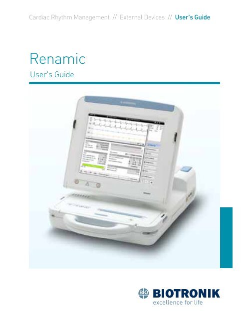
17 System OverviewSystem Overview<strong>Renamic</strong> is a portable programmer and monitoringdevice. It is used during the implantation and follow-up ofimplantable pulse generators and implantable cardioverterdefibrillators.The programmer is intended to be used forthe following tasks:• Conduct sensing, pacing threshold, and impedance tests.• Interrogate data stored on the implanted device,including program parameters, recorded statistical data,and episodes.• Record ECG "freeze" screens and real time IEGMs.• Display, print, save and export data stored on theimplanted device for analysis and reporting purposes.• Transfer parameters to and program the implanted device.
18 Device OverviewDevice OverviewAnti-slip PadsRelease ButtonsErgonomic HandleON/OFFLEDFigure 1: <strong>Renamic</strong> in transport position<strong>Renamic</strong> has an ergonomic handle in the front and a grippingtab in the back, which can be used to safely transport thedevice in any position. The specially designed anti-slip padsallow for horizontal or vertical positioning of the device.
19Device OverviewTouchscreenMultiple touch optionsBack compartmentPower cord storageFront compartmentProgramming headand ECG cable storagePGH Feed-throughFigure 2: <strong>Renamic</strong> in the operating positionWhile <strong>Renamic</strong> is in the transport position (screen closed,shown in Figure 1), unlock the screen by pressing bothrelease buttons, located on the right and left sides of thedevice, at the same time. The unlocking mechanism can beheard and felt when released. Hold the sides of the screenwith both hands and tilt the screen up to the operatingposition, as shown in Figure 2. The screen can pivot aroundthe upper end of the screen arm. The operating position canbe smoothly adjusted as needed and will hold a wide range ofworking positions.
20 Device OverviewFigure 3: Power cord storage compartmentThe power cord storage compartment, shown open inFigure 3, is located at the rear of <strong>Renamic</strong>. To open thiscompartment, simply push the compartment door in thedirection of the arrow displayed on top of the drawer. Thelocking mechanism will disengage, allowing for the door tobe swiveled up and open.
21 Start UpStart UpUSB Port(Recommendedfor Bluetooth ®Applications)ON/OFFLEDPGH Feed-throughFigure 4: Programming head compartment with lid open, viewed from aboveConnectingto <strong>Renamic</strong>Programming HeadThe programming head (PGH) port is inside the top-rightportion of the PGH compartment. To attach the PGH, pullthe short end of the cable out of the PGH compartment andconnect the PGH cable to the device PGH port. Feed the cableattached to the PGH through the PGH compartment feedthrough,as shown in Figure 4.Cables<strong>Renamic</strong> can be used with the PK-222 ECG cable, shown in
23 Start UpECG Port and USB Device PortsThe PK-222 cable can be attached via an ECG port located onthe back right of the device, as shown in Figure 6.Figure 6: ECG Port and USB PortsThere are three USB ports located on the back right of thedevice, as shown in Figure 6, and one USB port located inthe PGH compartment for the Bluetooth ® adapter, shown inFigure 4.A USB drive can be disconnected and reconnected while<strong>Renamic</strong> is still active.Note: Connecting and disconnecting USB devices may resultin malfunctioning.• Do not connect any USB devices other than the SafeSyncModule to the programmer during follow-up.• Do not disconnect any USB devices from the programmerduring follow-up.
24 Start UpBluetooth ®<strong>BIOTRONIK</strong> supplies a compatible Bluetooth ® adapter withthe programmer. When the Bluetooth ® adapter is connectedto the <strong>Renamic</strong>, various Bluetooth ® -compatible devices cancommunicate wirelessly with the programmer.The recommended port for the Bluetooth ® adapter islocated in the PGH compartment on the right side of thecompartment underneath the protective cap, as shown inFigure 4.<strong>Renamic</strong> arrives preconfigured with a Bluetooth ® adapter. Toconnect the Bluetooth ® adapter, if needed, follow the instructionsbelow:• Turn <strong>Renamic</strong> OFF. Proper installation of a Bluetooth ®adapter requires that <strong>Renamic</strong> be powered OFF.• Open the PGH compartment and remove the protectivecap from the port for the Bluetooth ® adapter.• Connect the Bluetooth ® adapter to the USB port.• Replace the protective cap over the Bluetooth ® adapter.
26 Start UpWhen possible, use the ON/OFF button on the softwareuser interface to turn the device OFF. Alternatively, toswitch the device OFF, press the ON/OFF button once.Note: Sudden disconnection from the power source can leadto the corruption of data.Note: The device does not automatically switch OFF whenthe screen is closed. Therefore, the device can be left in anoperational mode and put aside temporarily to save space. Byreopening the screen, the programmer becomes immediatelyfunctional again.
27 Using <strong>Renamic</strong>Keys,Displays,and SignalsUsing <strong>Renamic</strong>The device has several keys to which fixed functions areassigned. See Table 1 for a description of these keys.<strong>Renamic</strong> KeyFunctionOn/Off ButtonEmergency Shock ButtonVVISafe Program Button10 Key for setting printer speed to 10 mm/s25 Key for setting printer speed to 25 mm/s50 Key for setting printer speed to 50 mm/sTable 1: Summary of <strong>Renamic</strong> keysKey used to stop printingFeed button to feed the paper to thebeginning of the next pageThe ON/OFF light indicator shows whether the device isswitched ON (LED is lit) or OFF (LED is not lit). It is located onthe front left edge of the device, as shown in Figure 1.The device screen is a touch screen that is operated using astylus or the user’s finger. The screen displays items includingparameters and measured values, a surface ECG, IEGMs withmarker channels, and various buttons. Buttons on the screenrespond to light pressure from the stylus or finger.
28 Using <strong>Renamic</strong>EmergencyPrograms<strong>Renamic</strong> features two emergency buttons that implement asafe program or deliver an emergency shock by pressing asingle button. Both buttons are located on the bottom leftcorner of the screen, as shown in Figure 8.Figure 8: Emergency Pacing/Shock ButtonsEmergency PacingEmergency pacing uses the following parameters:• Mode:VVI• Basic rate: 70 ppm• Pulse amplitude: 7.5 V• Pulse width: 1.5 msThese parameters are non-programmable. To deliveremergency pacing, establish telemetry contact by positioningthe PGH above the implanted device or by enabling theSafeSync RF telemetry. Press the button. EmergencyVVIpacing will immediately commence. This may be done withboth pacemakers and ICDs.
29 Using <strong>Renamic</strong>To stop emergency pacing, load the Parameters screen.Program the desired permanent parameters and transferthem to the implanted device.Emergency ShockThe emergency shock (ICDs only) is delivered with thefollowing non-programmable specifications:• Waveform: Biphasic• Delivery Type: Synchronized with an R-wave• Energy: Maximum energyTo deliver an emergency shock, establish telemetry contactby positioning the PGH above the implanted device or byenabling the SafeSync RF telemetry. Press the button. Inthe dialog window, select EMERGENCY SHOCK. The ICD willimmediately begin charging and deliver a shock.Note: The emergency shock is a committed shock. Press thebutton only once each time you want to deliver a shock.Pressing the button multiple times (even as the device ischarging and there is no telemetry contact) may result inextra shocks being delivered.
30 Using <strong>Renamic</strong>TelemetryThe programmer and the implanted device communicatetelemetrically via the programming head or using SafeSyncRF telemetry. Not every device supports SafeSync RFtelemetry. Consult the technical manual of the respectiveimplantable pacemaker or ICD.SafeSync RF telemetry establishes a wandless telemetryconnection between the programmer and devices withthe <strong>BIOTRONIK</strong> SafeSync function. The programmer anddevices that offer the <strong>BIOTRONIK</strong> SafeSync function have aspecific type of transmitter with which high frequency radiotransmission is possible. Wandless telemetry involves theoutput data (digital as well as analog) from the implanteddevice being converted into digitally coded pulses andtransmitted over an inductive coupling between the coils ofthe programming head and those of the implanted device.With some implanted devices, telemetry cannot be carriedout until a reed switch in the implanted device has beenclosed. For this purpose, a strong permanent magnet hasbeen integrated into the programming head. Before theprogramming head and the implanted device can exchangedata, the reed switch in the implanted device is closed.When the reed switch is open, telemetry is blocked.This protects the implanted device from unintentionalreprogramming. With some implantable devices, closing thereed switch also switches the device over to an asynchronouspacing program. See the technical manual of the respectiveimplanted device.
31 Using <strong>Renamic</strong>Establishing SafeSync RF TelemetryThe establishment of SafeSync RF telemetry depends on thedevice being used. To establish SafeSync RF telemetry, placethe programming head over the device until the message“Programming head can be removed” appears. Once themessage appears (typically < 2 seconds) the programminghead can be removed. Proceed as described in the device'stechnical manual.The LED at the front of the programming head shows itsstatus:LED status (flashing)OrangeStatus programming headNot ready. (toggling to 'telemetryvia programming head' is onlypossible using the software.)Table 2: SafeSync RF Telemetry PGH LED Indicator ReferenceEstablishing Telemetry via Programming Head<strong>BIOTRONIK</strong> implanted devices can communicate with<strong>Renamic</strong> via the programming head (PGH). To establishtelemetry via the programming head, place the programminghead on the patient above the active implanted device so thatthe arrows are pointing toward the patient's head.Refer to Table 3 for a description of the LEDs on the PGH.
32 Using <strong>Renamic</strong>LED Status (flashing)GreenOrangeRedOFF / Not LitTable 3: PGH LED Indicator ReferenceTelemetry StatusTelemetry contact optimalTelemetry contact in limited rangeTelemetry contact disruptedNo telemetry contactAs soon as the PGH is correctly positioned over the implanteddevice (and telemetry has been established), the programdata and data stored in the implanted device, includingstatistics and parameter sets, are transmitted to <strong>Renamic</strong>.The PGH is equipped with its own safe program button. Thisfunction can be started immediately from any application ifthe programming head is positioned above the implanteddevice. For more information, see the Emergency Programssection on page 28.
33 Using <strong>Renamic</strong>DeviceProgramsThe following programs can be transmitted to theimplanted device:• Temporary program: A temporary program is a programthat the implanted device uses to provide temporarypacing when a test is being conducted and there istelemetry contact.• Permanent program: A permanent program is a programwith which the implanted device can provide constantpacing independently of telemetry contact.• Safe program: A program that is used for safety pacingwith high output in either a VVI or SSI mode.Use of a temporary program can be stopped at any timeand the permanent program of the implanted device can beautomatically reactivated with the following:• Telemetry via the programming headLift the programming head or switch off the programmer.• SafeSync RF telemetrySwitch the programmer off or move it out of the device'srange.
34 Using <strong>Renamic</strong>Using theInternal PrinterFigure 9: <strong>Renamic</strong> paper tray for internal printerThe <strong>Renamic</strong> printer has a high-definition thermal printerthat is capable of printing graphics. The device prints onthermal folding paper. The thermal paper printouts aremoisture and heat sensitive and will fade when exposed tostrong sunlight. Make copies for permanent documentation.Inserting paperTo insert paper into the tray, follow the steps described below:Figure 10: <strong>Renamic</strong> paper tray opened
35 Using <strong>Renamic</strong>• Open the paper tray.--Open the lid by lightly pushing it upwards.ооPrinters without release lever:• Pull the tray all the way out.ооPrinters with a release lever:• Press down the key on the right side andpull the tray all the way out.Figure 11: Inserting paper into tray• Insert paper.--Press back the separating flap (clear tab locatedwithin the paper drawer).--Pull back the first page of the paper block.--Place the block of paper in the tray from above, sothat when the paper lays over the roller, the blackrectangles are facing up.--Place the separating flap under the first sheet of paper.--Pull the first page over the separating flap andrubber roller.• Close the paper tray.--Push the tray back into <strong>Renamic</strong> until it stops.--The cover locks automatically.
36 Using <strong>Renamic</strong>PrintingFigure 12: Printer buttonsThe printer buttons are located on the left front side of the<strong>Renamic</strong>, as shown in Figure 12. For a description of eachbutton and its function, refer to Table 1 on page 27.
37 Using <strong>Renamic</strong>ECG and IEGMFunctionsTakingScreenshotsThe IEGMs received from the implanted device and surfaceECG can be displayed and printed simultaneously. Therecording of the surface ECG is independent of otherfunctions, so the implanted device can be interrogated andprogrammed during the ongoing ECG display. The recordedelectrograms can be saved and measured using calipers.When the ECG is overmodulated, the signal is displayed onlyas a solid line on the upper frame of the ECG window. To fix theovermodulation, test the lead contacts, remove other devicesfrom the patient, and turn off the sources of interference.To take a snapshot of the current screen displayed on<strong>Renamic</strong>, follow the instructions listed below:1. Make sure that the USB drive on which you wish to storethe image is plugged into one of the available USB ports.See page 23.2. Pull out the printer paper tray as if you were going toreplace the paper. The printer tray must be out in order totake screenshots.3. Press and hold the button.4. While holding the button, press and release the10 button.The screenshot is now saved to the USB stick as a PNG file.
38 <strong>Renamic</strong> PSAOverview<strong>Renamic</strong> PSAThe <strong>Renamic</strong> Pacing System Analyzer (PSA) is used duringthe implantation of pacemakers and defibrillators to evaluatethe placement and integrity of pacing/defibrillator leadsand to determine the appropriate pacing parameters for theimplanted lead(s).Figure 13: <strong>Renamic</strong> start-up screen<strong>Renamic</strong> performs a self-test during startup and the LEDsare initially all illuminated in green. Once the self-test hasbeen completed successfully, the LEDs are switched off,and the PSA button can be selected on the <strong>Renamic</strong> userinterface.
39 <strong>Renamic</strong> PSAIf the self-test is not successful, the LEDs quickly flashyellow/green. If the LEDs are continuously lit yellow/greenafter the self-test, then the software of the PSA module isbeing updated. Table 4 provides a description of the <strong>Renamic</strong>PSA LEDs:LabelARVLVLEDcolorGreenYellowGreenYellowGreenYellowTable 4: <strong>Renamic</strong> PSA LEDsStatusAtrial sensingAtrial pacingRight ventricular sensingRight ventricular pacingLeft ventricular sensingLeft ventricular pacingThe following Table 5 provides a list of patient cables andadapters that can be used with the <strong>Renamic</strong> PSA:<strong>Renamic</strong> PSAConnectionName Order no. DetailsPatient cable PK-67-L 123 672Connects analyzer/implant module to 301-CG.8.5 ft longPatient cable PK-67-S 123 438Connects analyzer/implant module to 301-CG.18 in longTable 5: <strong>Renamic</strong> PSA Connections
40 <strong>Renamic</strong> PSAConnecting thepatient cablesPatient cables can be connected or disconnected whilethe device is switched on. Patient cables should only beconnected to the device once it is ready for use. The currentparameter settings should be checked before connecting thepatient cable to the device.For the right side of the heart (A/RV):• Insert the Redel plug of the patient cable into the A/RVconnection. Make sure the plug is securely positioned inthe connection.• Connect the patient connections of the patient cable oradapter to the patient's A/RV leads.For the left side of the heart (LV):• Insert the Redel plug of the patient cable into the LVconnection. Make sure the plug is securely positioned inthe connection.• Connect the patient connections of the patient cable oradapter to the patient's left ventricular leads.Disconnecting the patient cables:Open the clamps and disconnect the lead from the patientcable or adapter and pull the Redel plug of the cable out ofthe device.Note:• Before connecting the patient cable to leads, make surethat the leads are securely implanted in the patient'sheart.• Do not force the plugs into the ports. When disconnectingplugs, do not pull on the cable.The user will be able to toggle between an interrogateddevice and the PSA function. If switching to the interrogateddevice screen, the current PSA function is still active.
41 <strong>Renamic</strong> PSAFigure 14: <strong>Renamic</strong> PSA main screenFigure 14 shows an overview of the PSA screen. The screen isdivided into four areas.1. The IEGM/ECG section provides marker channels, asurface ECG and intracardiac electrograms. The signalscalar can be adjusted by pressing the magnifying glassicon located on the left side of the screen. The patient’sheart rate is displayed in the upper left corner of thescreen if the patient is connected to a surface ECG. Thedown arrow on the bottom left corner of the ECG sectionprovides a full screen view of the signals.2. The real-time measurement section in the upperright corner provides information regarding ongoingmeasurements based on the active channels. Thissection is divided into the following:
42 <strong>Renamic</strong> PSAa. Rate – current rateb. Impedance – pacing impedance(s) will be displayedfor all channels in which pacing is occurring. It willbe blank if there is no pacing.c. Amplitude – will provide sensing amplitude(s) forall channels in which intrinsic activity is occurring.The sensing value will be blank in the presence ofpacing.d. Slew rate – measures signal excursion in V/sec.e. AV – The current AV Delay value in any dualchamberstate.f. The channel icons at the top of the page will flashgreen when sensing occurs and orange when pacingoccurs.3. The PSA module section shows information related to thetesting mode, rate, pacing, sensing and output currentlyset in the PSA module. These are programmable and willbe discussed in greater detail throughout the manual.Pressing the down arrow near the center of the screenon the Tests page displays additional programmableparameters.4. Master tab buttons to the right of the PSA modulesection allow the user to toggle between the Tests, Burstpacing and Report pages. The arrow button allows theuser to exit from the PSA programmer.Note: The <strong>Renamic</strong> PSA allows the user to maintain PSAfunction while exiting the screen to make programmingchanges to an implantable device. The user can re-enter thePSA module by pressing the PSA button on the screen.PSA data is saved to the programmer. To prevent confusion,enter the patient name or ID number in the Patient datasection on the Report page. This will allow the user to reviewspecific patient information. The file will be saved under the
43 <strong>Renamic</strong> PSA“device type” heading of PSA Module. The patient name willbe blank if the patient information is not added.Note: If an implantable device is interrogated, the PSA datawill be stored under the interrogated device in the devicemanager under the heading PSA Module.PSAModuleParameter OverviewParameter Range RemarksModeTrackingBasic RateChannelPacingAmplitudeDDD, DDI, VDD,AAI, VVI, DOO,AOO, VOO,OFF/ODOON, OFF30...(1)...180 bpmON, OFFON, OFF0 – 10 VTable 6: PSA parameter OverviewAllows the user to select thedesired mode for testing.Switches between tracking andnon-tracking modes (DDD toDDI) without requiring the popupmenu for modesAllows the user to set the lowerpacing rate.Allows the user to turn offchannels not in use. SelectingOFF will remove the channelfrom being visible on the display.Turns OFF pacing for theselected channelDisplays a slide bar and +/-icons allowing the user to testthresholds. The user can eitherslide the icon to increase ordecrease amplitude output orpress the + or – buttons.
44 <strong>Renamic</strong> PSAParameter Range RemarksSensingPulse WidthON, OFF0.1 – 2.0 msTurns sensing ON or OFF for aselected channel.Allows the user to adjust thepulse width of a pacing pulse.Recommend using the samevalue as the implanted device.The parameters shown below are accessed by pressing the “down”arrow icon next to the LV channel header. Refer to Figure 14. Toreturn to the main parameters, press the “up” arrow icon next to theLV channel header.SensitivityAV/VV DelayLV PolarityA = 0.2 – 20 mVRV/LV = 0.5 – 20mVAV Delay = 0 –300 msVV Delay =-100 to +100 msBipolarCommon RingBipolarInverted bipolarRing to ringbipolarTable 6: PSA parameter OverviewAdjusts the sensing floor foreach chamber.AV Delay – In dual-chambermodes, the user can programAV Delay up to 300 ms fortesting purposesVV Delay – selecting a negativevalue results in the LV pacingoccurring first. Selecting apositive value results in RVpacing occurring firstAllows the user to choose aLV pacing configuration if BiVtesting occurs
45 <strong>Renamic</strong> PSAPreferredSettingsThe Preferred Settings button allows the user to select savedparameter settings or set new default preference settings.Figure 16: Preferred settingsSavingMeasurementsLoad – Loads a previously saved program.Save – Saves a user defined program into the memory. Onlyone program may be stored.Factory settings – Resets the program to the preset factoryprogram. Also clears any save program.Cancel – Closes the Preferred Settings screen.To save measurements, select the desired channel. Selectthe measurement to be saved. Refer to Figure 17 for anexample of saving an RV measurement. For example, if anRV sensing measurement is being performed, select the RVchannel (blue box) and press Sensing (green box). This savesthe data to the report page. A message stating the value wassaved to the programmer will be displayed on the messageline.
46 <strong>Renamic</strong> PSAFigure 17: Saving measurement valuesMax.pacingNOTE: The button does not need to be held down to save themeasurement values.Max. pacing will deliver the maximum pacing output(10 V) to the desired chamber to look for phrenic nerve ordiaphragmatic stimulation. This is shown in the blue boxes inFigure 18. To deliver maximum pacing, ensure that pacing isoccurring in the specified chamber and press/hold the Max.pacing button. Releasing the button will return the pacingoutput to the previous value.
47 <strong>Renamic</strong> PSAFigure 18: Max. pacingBurstPacingBurst pacing allows the user to deliver burst pacing in thedesired chamber. The Burst pacing range is from 80 to1000 bpm. The output for Burst pacing will be set at 7.5 voltsat 1.0 ms. An example of the burst pacing screen is shown inFigure 19.
48 <strong>Renamic</strong> PSAFigure 19: Burst pacingTo deliver Burst pacing, program the PSA module to thedesired program. Select the Mode and whether or nottracking is desired. It is recommended to set the mode toDDD or DDI for atrial burst pacing to provide back-up pacingsupport in the ventricle. Set the basic rate for supportpacing. The range is from 30-180 bpm.Select the desired channel for burst pacing. If a ventricularchannel is selected, a warning message will appear as seenin Figure 20.
49 <strong>Renamic</strong> PSAFigure 20: Warning message for ventricular burst pacingReportPress the OK button on the message screen to continue.Use the slide bar to increase the pacing rate in theprogrammed chamber. Releasing the button returns the rateto 80 bpm.NOTE: Emergency medical equipment should always beavailable when burst pacing is performed.The report page, shown in Figure 21, presents a summaryof saved data from testing. The data is stored in theprogrammer, and this page may be printed, as well. Ifmultiple testing occurs, the last data point tested will bestored for that session.
50 <strong>Renamic</strong> PSAFigure 21: Completed report pageThe patient data section, shown in Figure 22, allows the userto input patient data similar to what may be stored in animplanted device. However, the data is not transferable to animplantable device. The data is stored in a file within the datamanager of the programmer.Note: this section is not available if the device to be implantedhas already been interrogated. In other words, if the device tobe implanted has been interrogated it is assumed the patientinformation will be added to the device.The PSA file created will become part of the interrogateddevice file within the data manager of the programmer.
51 <strong>Renamic</strong> PSAFigure 22: Patient data screenSensingImplant TestingAfter the lead is connected to the PSA module, the unfilteredIEGM signal will appear with sensing values on the displayscreen and in the real-time measurement section to the rightof the display screen, as shown in Figure 23. To save the datato the programmer, select the chamber being tested in theSave measurement section. The RV channel is selected andshown in the blue box. Pressing the Sensing button (greenbox) will save the sensed data for the selected chamber in theReport screen. A message stating “Values saved” (red box)will appear on the message bar.Figure 23 shows a sensing test for the RV lead beingperformed, though all connected lead values will bedisplayed.
52 <strong>Renamic</strong> PSAFigure 23: Sensing test for the RV channelImpedanceTo test the impedance, program the desired output andincrease the basic rate to 10-15 beats above the intrinsicrate to ensure pacing. The impedance value is displayed inthe real-time screen in the upper right corner of the screen.Real-time impedance values are displayed in the right uppercorner, as shown in the black box in Figure 24.Select the chamber to record the impedance measurement;an example using the LV channel is shown in the blue box inFigure 24. Press the Impedance button (green box) underthe Save measurement section to save the data to the Reportscreen. A message stating “Values saved” will appear on themessage bar, shown with the red box in Figure 24.
53 <strong>Renamic</strong> PSAFigure 24: Impedance testThresholdTo start the threshold test, first select the chamber beingmeasured under the Save measurement section. An exampleis shown in the blue box in Figure 25. Press the amplitudebutton (black box) for the chamber being tested, in this casethe RV channel. Decrease the output by using the slidebaror – button until capture is lost. Increase the output toregain threshold and press the Threshold button under theSave measurement section to save the data to the Reportscreen. A message stating “Values saved” will appear on themessage bar, as shown with the red box in Figure 25.Increase the output if the patient is pacemaker dependent toregain capture or decrease the rate to end the test.
54 <strong>Renamic</strong> PSAFigure 25: Threshold testPhrenic nerve or diaphragmatic stimulation can be testedby pressing and holding down the Max. pacing button. Thepacing output during maximum pacing is 10 V @ 2.0 ms.Release the button to stop maximum output pacing. Theoutput will return to the previously programmed values.ReportReportThe Report page provides a summary of all testing completedto include value measurements, testing values, and time oftesting. This report can be printed at the time of implantationfor documentation or saved to the programmer.
55 <strong>Renamic</strong> PSAFigure 26: Report pageAdjust IconAdditional FunctionsImmediately to the left of the freeze icon is an adjust icon.Pressing the adjust icon , located to the right of thePSA button, brings up the pop-up menu shown in Figure 27,which allows the user to change screen sweep speed, displaycolor scheme, ECG display for testing, gains for the ECGand IEGMs, as well as the display mode. Any of these can bechanged without rebooting the programmer.
56 <strong>Renamic</strong> PSAFigure 27: Adjust screenSpeedAdjusts the sweep speed of the display.ECGSelects the ECG lead to be visualized during testing. Acheck box underneath the ECG section allows the user touse the far-field signal instead of the ECG for devices thatuse a far-field signal. The checkbox will only apply to thoseimplantable devices capable of transmitting a far-field signal.Color schemeChanges the color scheme of the ECG/IEGM display to whiteon-blackor black-on-white and the colors of the channeldisplay.AC FrequencyAllows the user to choose 50 Hz or 60 Hz frequency. It isrecommended to keep at 60 Hz.
57 <strong>Renamic</strong> PSAFreezeScreenGainAnother method to adjust the size of the on-screen signal forECGs and IEGMs.FilterAllows the user to choose a filtered or unfiltered signal.Overwrite / ContinuousTwo options are available for choosing how data crosses thescreen. The Overwrite mode brings new information in fromthe right side of the screen. The Continuous mode bringsnew information in from the left side of the screen.StandardResets the settings to a standard default.StoreStores into memory any changes made by the user.ClosesCloses the adjust window with changes.The freeze icon may be used to capture a snapshot of theIEGM. Calipers will appear with the snapshot, allowing theuser to measure intracardiac distances and amplitude values.Calipers can be adjusted by touching the vertical dotted lineson the screen, as shown in Figure 28, or by using the arrowson the right side of the screen.
58 <strong>Renamic</strong> PSAFigure 28: The Freeze ECG pageThe programmer is capable of storing the last 60 seconds oftemporary memory when the Freeze icon is selected. Thisinformation can be printed by the user. The Print/Save optionsare opened when pressing on “Window Content,” found onthe bottom-right corner of the programmer screen, as shownin Figure 29 with a red box. When pressing on “WindowContent”, the window in Figure 30 appears. Whichever optionis selected is the portion that can be printed or stored to theprogrammer.
60 <strong>Renamic</strong> PSAbetween the calipers at 25 mm per second paper speed.1-2 Caliper 50 mm/s – prints/saves only the informationbetween the calipers at 50 mm per second paper speed.These are printed by pressing the print button in the bottomright corner of the screen, as shown in Figure 29.The Store button below the Window content stores the frozeninformation to the programmer for later viewing.The table in the upper right portion of the screen shows thesignal amplitude that crosses the calipers.The Close button turns off the freeze and returns theprogrammer to standard function.IDPatient DataPatient data can be added to the PSA file, which is stored inthe programmer. This allows user to go back and review filesfor a specific patient if needed. The data is similar to the datafields of the implanted device.The patient data section is found under the Report tab of thePSA module.This section allows the user to input up to a twelve-digit codeto serve as a patient identifier. This may be a medical recordsnumber or a study number if the patient is enrolled in a study.
61 <strong>Renamic</strong> PSAFigure 31: ID NumberFirst Name/Last NameThese sections allows the user to input the patient’s first andlast name into the PSA file. This is a free text box, allowingup to 19 characters for the first name, as well as for the lastname. Enter the patient’s name and select the enter key.Figure 32: First NameFigure 33: Last Name
62 <strong>Renamic</strong> PSADateof BirthThis section allows the user to input the patient’s birth date.The birth date is entered as MM/DD/YYYY, as shown in Figure34. When initially accessed, the current day will be displayed.The date can be changed using the following methods:• Selecting the keypad icon to the left of the OK button willbring up a number keypad allowing the user to manuallyinput the date.• The day can be selected simply by touching theappropriate day on the screen.• Pressing the month will bring up a listing of the 12months, and the user can select the appropriate month.• Selecting the year will bring up a numeric keypad,allowing the user to enter a year.• The double arrow will change the year by one value eachtime it is touched. The left double arrows decrease thevalue and the right double arrows increase the value.• The single arrow will change the month by one. The leftarrow decreases the value and the right arrow increasesthe value.Once the date is entered, select the OK button
63 <strong>Renamic</strong> PSAFigure 34: Date of BirthGenderThis section allows the user to select the patient’s gender.Figure 35: Gender
65 <strong>Renamic</strong> PSAFigure 38: EtiologyImplantationThis section allows the user to input the implant date. Theimplant date is entered as MM/DD/YYYY, as shown in Figure39 When initially accessed, the current day will be displayed.The date can be changed using the following methods:• Selecting the keypad icon to the left of the OK button willbring up a number keypad allowing the user to manuallyinput the date.• The day can be selected simply by touching theappropriate day on the screen.Figure 39: Implant Date
66 <strong>Renamic</strong> PSAHospitaland CityThe hospital name and city name can be added. As withentering the patient’s name, up to 19 characters are availableto add hospital and city information.Figure 40: Hospital, CityPhysicianThe physician name and phone number can be added. Thephysician name can be entered in the left side box and thephone number on the right side box. As with the patientname, up to 19 characters are available to add physicianinformation. It is a good idea to add the physician’s firstname to help prevent confusion.Figure 41: Physician information
67 <strong>Renamic</strong> PSARemarkFree text remarks can be entered into the device. Up to 86characters (including spaces) can be entered.Figure 42: RemarksLeadInformationLeadtype<strong>Renamic</strong> PSA series allows atrial and ventricular leadinformation to be added to the patient data stored in the<strong>Renamic</strong> programmer.The lead type can be entered here using both letters andnumbers. An example would be Setrox S 53.Figure 43: Lead Model number
69 <strong>Renamic</strong> PSATypeThe type of lead (unipolar, bipolar, etc.) can be added for theatrial and ventricular leads.Figure 46: Lead typeImplantationThis box allows the user to enter the implantation date of theleads.Figure 47: Implantation dateChannelsThis box allows the user to choose the channel to whichthe lead is connected. The left column is for the chamber inwhich the lead is placed. The right-hand column is for ICDleads and the placement of the shock coils.
70 <strong>Renamic</strong> PSAFigure 48: Lead channelPrinting the informationThe implant information can be printed directly from theprogrammer at the time of implant or later from the datamanager. To prevent confusion, the patient name or IDnumber should be entered into the patient data page asdescribed on page 60. An example of the data page is shownin Figure 49.Figure 49: Testing information
71 <strong>Renamic</strong> PSAIf a device is interrogated at the time of lead testing, the PSAtest information will be placed on the follow-up section ofthe preview page within the device manager; an example isshown with the red box in Figure 50.Figure 50: PSA module information
72 <strong>Renamic</strong> PSAPreviewing the information from the PSA module will displaythe results, as seen in Figure 51. The printed version willhave the same look.Figure 51: PSA module preview
73 MaintenanceMaintenanceTo clean and disinfect <strong>Renamic</strong>, follow the instructions below:• Use soft, lint-free cloths.• Clean the housing with a damp cloth and mild soapsolution or 70% isopropanol.• Disinfect with alcohol or aldehyde-based agents suchas Aerodesin 2000, Fugaten spray, Lysoformin 2000 orAldasan 2000.• Vacuum the ventilation slots regularly.• Visually inspect the connections: make sure that thecontacts for all connections and cables are clean and freeof any type of dirt.• To disinfect the patient cable and patient adapter, use amixture of 70% isopropanol and 30% water, or if usingLysoformin 3000 allow 15 minutes at 2% concentration forit to take effect.Neither <strong>Renamic</strong> nor the PGH can be sterilized. To use thePGH inside of the sterile field, a sterile wand cover must beplaced over the programming head and cord.
74 SafetySafetyTo ensure patient safety and proper device function, adhere tothe following safety precautions when using <strong>Renamic</strong>:• Only use the programmer in accordance with theTechnical Manual and User’s Guide.• Only the manufacturer or a party expressly authorizedby <strong>BIOTRONIK</strong> may perform corrective maintenance,enhancements, or modifications to the device.• Use only original replacement parts and accessoriesauthorized by <strong>BIOTRONIK</strong>. Using any other parts voids themanufacturer’s liability for any consequences, guaranteeand warranty.• Do not use defective or damaged units or accessories.• Only use the device under the constant supervision of aphysician.• Ensure that patients are individually observed over asuitable period of time in order to monitor the compatibilityand effectiveness of parameter combinations.• Always ensure that in the event of an emergency thefollowing basic equipment is available:--Defibrillator--Oxygen--Intubation set--Emergency drugsFor pacemaker-dependent patients, an additionalexternal pacemaker must also be available.
75 SafetyOperatingConditions• Do not use this device as a life support system.• Protect the device from accidental contact with fluids.• During implantation procedures, ensure the patient’s heartrate is monitored using an ECG monitor or ECG recorder.• During defibrillation, do not touch the patient, theprogrammer the patient is connected to, or the attachedaccessories. Otherwise, there is a danger that the usermay suffer an electrical shock.If the package is damaged, contact <strong>BIOTRONIK</strong> immediately.Do not put the device into operation.Mechanical impact, e.g., dropping the unit, can permanentlyimpair the function of the device. Do not use the device if itshows visible damage. Contact <strong>BIOTRONIK</strong> for testing and, ifnecessary, repair of the equipment.Replace any cables that show even slight damage. Ensurethat the contacts of all connections and plugs are clean.Ensure that no condensation on the plugs or connector portsexists prior to use. If condensation is present, dry before use.Place the device on a flat, dry surface so that the patient canonly come into contact with the applied parts, namely theprogramming head and ECG cable.
76 Electromagnetic Interference and GroundingElectromagnetic Interference and GroundingThe programmer is protected from disturbances resultingfrom electromagnetic interference, electrostatic dischargesand other sources, including interference from cables.However, strong electromagnetic interferences that occurin the close vicinity of electrical motors, power cables, PCs,monitors, or other electrical devices may compromise thefunction of the programmer in certain cases.Correct operation of the device can be restored withthe following:• Turn off other electronic devices.• Remove any known source of electromagnetic interference.• Turn the programmer ON and OFF or break the electricalconnection between the programmer and the source of theinterference as much as possible without causing danger.The telemetry between the programming head and theimplanted device can be impaired by electromagneticinterference (EMI). This can be observed when it becomesdifficult or even impossible to interrogate or program theimplanted device. Using the EMI test, the source of theelectromagnetic interference can be located.<strong>Renamic</strong> PSAIn the case of disruptions resulting from electromagneticinterference (EMI) that exceed the limit, the PSA moduleswitches to asynchronous pacing. The sensing amplifier isswitched off for the duration of the disruption in the channelin which the disruption is detected. Pacing continues if it isswitched on in this channel. These disruptions are visible inthe IEGM channel, but no markers are displayed.
77 Technical DataTechnical DataSee the tables below for specific device information.<strong>Renamic</strong> Physical characteristicsCategoryDimensions (L x W x H)Weight (with cables and PGH)Housing materialDesign18.7 x 13.6 x 4.9 in23.1 lbsPC/ABSTable 7: Physical Characteristics of <strong>Renamic</strong> programmerCategoryDimensions (L x W x H)WeightHousing materialPatient connectionsDesign4.5 x 5.7 x 1.1 in7.1 ozPC/ABS2 PKN06 Redel plugsTable 8: Physical Characteristics of <strong>Renamic</strong> PSA
78 Technical DataAmbient conditionsCategoryTemperature range for operationTemperature range for storageRelative humidityAtmospheric pressureOperation at altitudesDesign+50°F … +104°F+32°F … +122°F30% … 75%,no condensation0.69 atm … 1.05 atmUp to 9842 ftTable 9: Acceptable Ambient Operating Conditions for <strong>Renamic</strong>Programming headCategoryApplied part classificationDimensions (L x W x H)WeightPGH cableInterfaceDesignBF5.7 x 3.8 x 1.7 in1.1 lbs9.5 ftRedel plug, 14-pinTable 10: Physical Specifications for the PGH
79 Technical DataInternal printerCategoryPrinter typePrinting widthResolutionPaperPaper format (B x L)Paper supplyDesignThermal printer4.4 in203 dots/inZ-fold thermal4.4 x 4.9 in210 sheetsTable 11: Specifications for the Internal Printer
80 Technical DataParameterModePSA ParametersActive channelsPaceSenseSpecificationDDD, DDI, VDD, VVI,VOO, AAI, AOO, DOO,OFF/ODOA: ON, OFF; RV: ON, OFF;LV: ON, OFFA: ON, OFF; RV: ON, OFF;LV: ON, OFFA: ON, OFF; RV: ON, OFF;LV: ON, OFFFactorySettingsOFF/ODOA: ON, RV: ON,LV: OFFA: OFF, RV:OFF, LV: OFFA: ON, RV:ON, LV: OFFTracking ON, OFF OFFAV delay 0…(5)…300 ms 120 msVV delay (RV→LV) -100…(5)…100 ms +5 msBasic rate (A, RV, LV) 30…(1)...180 bpm 90 bpmPulse amplitude(A, RV, LV)0.1…(0.1)…10 V5 VPulse width(A, RV, LV)0.1…(0.1)…2.0 ms 0.4 msSensitivity, atrium 0.2…(0.1)…20 mV 1.0 mVSensitivity, RV/LV 0.5…(0.1)…20 mV 2.5 mVLV: Pacing polarityBIPL, CRBP, IVBP,RRBPBIPLIEGM Filter ON/OFF ONBurst frequency 80…(10)…1000 bpm 80 bpmTable 12: <strong>Renamic</strong> PSA Parameters
81 Supplementary InformationSupplementary InformationScope of Delivery and Accessories<strong>Renamic</strong> (Order no.: 371960)Item designation Amount Order no.Programming head (with magnet) 1 371 588Power cord 1 —PK-222-US / 2.8 m (9.2 ft) 1 335 281Bluetooth USB adapter 1 —Stylus 1 —Thermal printer paper 2 348 728PK Electrode Clip (set of 4) 1 340 293Technical Manual 1 377 213Quick Reference Guide 1 370 977<strong>Renamic</strong> PSA Module 1 386 610<strong>Renamic</strong> PSA Quick Reference Guide 1 386 606Table 13: List of accessories
82 Supplementary InformationAccessoriesItem designation DescriptionPK-222-US / 2.8 m(9.2 ft)PGH ICDUSB adapter forVGA portStylusOrder no.ECG cable with banana plug forextremity leads according to 335 281EinthovenProgramming head withoutmagnet with straight cable 371 5892.9 m (9.5 ft)OrderableVirtual VGA interface via USB throughsales repMagnetic, soft tip, for use on—touch screenThermal printerpaperThermal printer paper —Patient cablePK-67-LApplicable with PK-155 123 672Patient cable PK-67-SApplicable with PA-2, PA-4 123 438Patient cablePK-141353 181Table 14: List of additional accessoriesCountry-Related InformationUL certification<strong>Renamic</strong> has been certified by Underwriters Laboratories Inc.with respect to electrical shock, fire and mechanical hazardsonly in accordance with:• UL 60601-1• CAN/CSA C22.2 No. 601.1• IEC 60601-1: 1988 + A1 + A2
83 Supplementary InformationUL-certified devices are identified as follows:Figure 52: UL identification on the deviceDistribution in the US and CanadaIn the US and Canada, the device must be connected to acenter-tapped power outlet if the voltage network carries230 V at 60 Hz.MarkerIndustry Canada:• <strong>Renamic</strong>: 4708A-RENAMIC• Programming head: 4708A-ICSPGHThe code IC in front of the approval/registration numberindicates that the technical requirements for IndustryCanada are met.
84 Supplementary InformationFederal Communication Commission of the <strong>USA</strong>:• <strong>Renamic</strong>: QRIRENAMIC• Programming head: QRIICSPGHModifications which are not expressly approved by thiscompany may void the rights to operate the devices.FCC HF exertion requirementsThe device is equipped with a high-frequency (HF)sender and receiver for wireless communication. Thiscommunication is transmitted via an HF that is approved bythe Federal Communications Commission (FCC) for medicalcommunication services (MICS).This device may not interfere with stations operating in therate range of 400.150 - 406.000 MHz in the meteorologicalaids, meteorological-satellite, and earth exploration-satelliteservices and must accept any interference received, includinginterference that may cause undesired operation.This device fulfills Part 15 of the FCC rules and regulations.The operation is subject to the following two conditions: (1)The device must not cause any harmful interference and (2)the device must handle any interference received, includinginterference that may cause undesired operation.
86 Symbols on the ComponentsThe symbols mean the following:<strong>Renamic</strong>PrinterSymbolsKey for setting printer speed to 10 mm/sKey for setting printer speed to 25 mm/sKey for setting printer speed to 50 mm/sKey used to stop printingFeed button to feed the paper to the beginningof the next pageThe symbols mean the following:Symbolson the<strong>Renamic</strong>PSAARVLVsensepacepacemaker applied part CF, defibrillatorprotectedAtriumRight VentricleLeft VentricleSensingPacing
87 Symbols on the ComponentsSymbolsin the PGHCompartmentThe symbols mean the following:Programming head connection with appliedpart classification BFUSB portPosition and connection of the programminghead and position of the ECG cableFollow the instructions in the technical manualSymbolson theProgrammingHeadThe symbols mean the following:Symbol for the safe program keyPosition indicator for the programming head
88 Symbols on the ComponentsLegend for the LabelThe label icons symbolize the following:Manufacturing date<strong>BIOTRONIK</strong> order numberSerial numberAcceptable temperature ranges for storageAcceptable atmospheric pressure range forstorageAcceptable relative humidity range for storageNon-sterileFollow the instructions in the technical manualContentsDo not use if package is damagedEuropean approval markCountry-specific restrictions concerning thecirculation and implementation of the device
89 Symbols on the ComponentsCaution: Federal (U.S.A.) law restricts thisdevice to sale by, or on the order of, a physicianDevice contains materials that must becorrectly disposed of in accordance withenvironmental protection regulations. EuropeanDirective 2002/96/EC regarding waste electricaland electronic equipment (WEEE) applies.Return devices that are no longer used to<strong>BIOTRONIK</strong>.Programmer (<strong>Renamic</strong>) for electrotherapyimplanted devicesCable and adapterProgramming headWarning: Magnetic fieldPSA module
M4147-B 07/13© 2013 <strong>BIOTRONIK</strong>, Inc.All rights reserved.MN017r3 7/11/13<strong>BIOTRONIK</strong>, Inc.6024 Jean RoadLake Oswego, OR 97035-5369(800) 547-0394 (24-hour)(800) 291-0470 (fax)www.biotronik.com