ZY7120 20A DC-DC Intelligent POL Data Sheet - Power-One
ZY7120 20A DC-DC Intelligent POL Data Sheet - Power-One
ZY7120 20A DC-DC Intelligent POL Data Sheet - Power-One

Create successful ePaper yourself
Turn your PDF publications into a flip-book with our unique Google optimized e-Paper software.
<strong>ZY7120</strong> <strong>20A</strong> <strong>DC</strong>-<strong>DC</strong> <strong>Intelligent</strong> <strong>POL</strong> <strong>Data</strong> <strong>Sheet</strong>3V to 13.2V Input 0.5V to 5.5V Output4. Electrical SpecificationsSpecifications apply at the input voltage from 3V to 13.2V, output load from 0 to <strong>20A</strong>, ambient temperature from -40°C to 85°C, 100F output capacitance, and default performance parameters settings unless otherwise noted.4.1 Input SpecificationsParameter Conditions/Description Min Nom Max UnitsInput voltage (V IN )At V IN
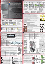
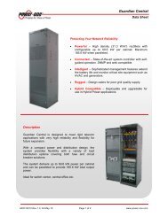
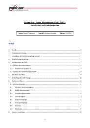
<strong>ZY7120</strong> <strong>20A</strong> <strong>DC</strong>-<strong>DC</strong> <strong>Intelligent</strong> <strong>POL</strong> <strong>Data</strong> <strong>Sheet</strong>3V to 13.2V Input 0.5V to 5.5V OutputFigure 1. Output Voltage as a Function of Input Voltage and Output Current4.3 Protection SpecificationsParameter Conditions/Description Min Nom Max UnitsOutput Overcurrent ProtectionTypeThresholdDefaultProgrammableDefaultProgrammable in 11 steps 50Non-Latching, 130ms periodLatching/Non-Latching140140%I OUT%I OUTThreshold Accuracy -25 25 %I OCP.SETOutput Overvoltage ProtectionTypeThresholdDefaultProgrammableDefault130Programmable in 10% steps 110 1Non-Latching, 130ms periodLatching/Non-Latching130%V O.SET%V O.SETThreshold Accuracy Measured at V O.SET =2.5V -2 2 %V OVP.SETDelayFrom instant when threshold is exceeded untilthe turn-off command is generated6 μsZD-00194 Rev. 2.5, 01-Jul-10 www.power-one.com Page 4 of 34
<strong>ZY7120</strong> <strong>20A</strong> <strong>DC</strong>-<strong>DC</strong> <strong>Intelligent</strong> <strong>POL</strong> <strong>Data</strong> <strong>Sheet</strong>3V to 13.2V Input 0.5V to 5.5V OutputTypeThresholdOutput Undervoltage ProtectionDefaultProgrammableDefaultProgrammable in 5% steps 75Non-Latching, 130ms periodLatching/Non-Latching7585%V O.SET%V O.SETThreshold Accuracy Measured at V O.SET =2.5V -2 2 %V UVP.SETDelayTypeFrom instant when threshold is exceeded untilthe turn-off command is generatedOvertemperature ProtectionDefaultProgrammable6 μsNon-Latching, 130ms periodLatching/Non-LatchingTurn Off Threshold Temperature is increasing 130 CTurn On ThresholdTemperature is decreasing after the module wasshut down by OTP120 CThreshold Accuracy -5 5 CDelayTypeFrom instant when threshold is exceeded untilthe turn-off command is generatedTracking Protection (when Enabled)DefaultProgrammable6 μsDisabledLatching/Non-Latching, 130ms periodThreshold Enabled during output voltage ramping up 250 mV<strong>DC</strong>Threshold Accuracy -50 50 mV<strong>DC</strong>DelayFrom instant when threshold is exceeded untilthe turn-off command is generatedOvertemperature Warning6 μsThreshold Always enabled, reported in Status register 120 CThreshold Accuracy -5 5 CHysteresis 3 CDelayLogicLower ThresholdFrom instant when threshold is exceeded untilthe warning signal is generated<strong>Power</strong> Good Signal (PGOOD pin)V OUT is inside the PG windowV OUT is outside the PG windowDefaultProgrammable in 5% steps 906 μsHighLow9095N/A%V O.SET%V O.SETUpper Threshold 110 %V O.SETDelayFrom instant when threshold is exceeded untilstatus of PG signal changes6 μsThreshold Accuracy Measured at V O.SET =2.5V -2 2 %V O.SET___________________1 Minimum OVP threshold is 1.0VZD-00194 Rev. 2.5, 01-Jul-10 www.power-one.com Page 5 of 34
<strong>ZY7120</strong> <strong>20A</strong> <strong>DC</strong>-<strong>DC</strong> <strong>Intelligent</strong> <strong>POL</strong> <strong>Data</strong> <strong>Sheet</strong>3V to 13.2V Input 0.5V to 5.5V Output4.4 Feature SpecificationsParameter Conditions/Description Min Nom Max UnitsTypeMaximum Number of ModulesConnected in ParallelMaximum Number of ModulesConnected in ParallelCurrent ShareActive, Single LineI OUT MIN ≥20%*I OUT NOM 10I OUT MIN =0 4Current Share Accuracy I OUT MIN ≥20%*I OUT NOM ±20 %I OUTInterleave (Phase Shift)Turn ON DelayTurn OFF DelayTurn ON Slew RateTurn OFF Slew RateLoad RegulationZero1 (Effects phase lead andincreases gain in mid-band)Zero 2 (Effects phase lead andincreases gain in mid-band)Pole 1 (Integrator Pole, effectsloop gain)Pole 2 (Effects phase lag andlimits gain in mid-band)Pole 3 (High frequency low- passfilter to limit PWM noise)InterleaveDefaultProgrammable in 11.25 steps 0SequencingDefaultProgrammable in 1ms steps 0DefaultProgrammable in 1ms steps 0TrackingDefaultProgrammable in 7 steps 0.1DefaultProgrammable in 7 steps -0.1Optimal Voltage PositioningDefaultProgrammable in 7 steps 0Feedback Loop Compensation0000.1-0.10348.7525563DegreedegreemsmsmsmsV/ms8.33 1 V/msV/ms-8.33 1 V/ms6.02mV/AmV/AProgrammable 0.05 50 kHzProgrammable 0.05 50 kHzProgrammable 0.05 50 kHzProgrammable 1 1000 kHzProgrammable 1 1000 kHzMonitoringVoltage Monitoring Accuracy1 LSB=22mV-2%V OUT– 1 LSB2%V OUT+ 1 LSBmVCurrent Monitoring Accuracy 20%*I OUT NOM < I OUT < I OUT NOM -20 +20 %I OUTTemperature Monitoring Accuracy Junction temperature of <strong>POL</strong> controller -5 +5 CRemote Voltage Sense (+VS and –VS pins)Voltage Drop Compensation Between +VS and VOUT 300 mVVoltage Drop Compensation Between -VS and PGND 100 mV___________________1 Achieving fast slew rates under specific line and load conditions may require feedback loop adjustmentZD-00194 Rev. 2.5, 01-Jul-10 www.power-one.com Page 6 of 34
<strong>ZY7120</strong> <strong>20A</strong> <strong>DC</strong>-<strong>DC</strong> <strong>Intelligent</strong> <strong>POL</strong> <strong>Data</strong> <strong>Sheet</strong>3V to 13.2V Input 0.5V to 5.5V Output4.5 Signal SpecificationsParameter Conditions/Description Min Nom Max UnitsVDD Internal supply voltage 3.15 3.3 3.45 VSYNC/DATA Line (SD pin)ViL_sd LOW level input voltage -0.5 0.3 x VDD VViH_sdVhyst_sdHIGH level input voltageHysteresis of input Schmitt trigger0.75 xVDD0.25 xVDDVDD + 0.50.45 xVDDVoL LOW level sink current @ 0.5V 14 60 mATr_sd Maximum allowed rise time 10/90%VDD 300 nsCnode_sd Added node capacitance 5 10 pFIpu_sd Pull-up current source at Vsd=0V 0.3 1.0 mAFreq_sd Clock frequency of external SD line 475 525 kHzTsynq Sync pulse duration 22 28T0 <strong>Data</strong>=0 pulse duration 72 78Inputs: ADDR0…ADDR4, EN, IMVV% of clockcycle% of clockcycleViL_x LOW level input voltage -0.5 0.3 x VDD VViH_x HIGH level input voltage 0.7 x VDD VDD+0.5 VVhyst_x Hysteresis of input Schmitt trigger 0.1 x VDD 0.3 x VDD VRdnL_ADDRExternal pull down resistanceADDRX forced low<strong>Power</strong> Good and OK Inputs/Outputs10 kOhmIup_PG Pull-up current source input forced low PG 25 110 μAIup_OK Pull-up current source input forced low OK 175 725 μAViL_x LOW level input voltage -0.5 0.3 x VDD VViH_x HIGH level input voltage 0.7 x VDD VDD+0.5 VVhyst_x Hysteresis of input Schmitt trigger 0.1 x VDD 0.3 x VDD VIoL LOW level sink current at 0.5V 4 20 mACurrent Share Bus (CS pin)Iup_CS Pull-up current source at VCS = 0V 0.84 3.1 mAViL_CS LOW level input voltage -0.5 0.3 x VDD VViH_CSVhyst_CSHIGH level input voltageHysteresis of input Schmitt trigger0.75 xVDD0.25 xVDDVDD+0.50.45 xVDDIoL LOW level sink current at 0.5V 14 60 mATr_CS Maximum allowed rise time 10/90% VDD 100 nsVVZD-00194 Rev. 2.5, 01-Jul-10 www.power-one.com Page 7 of 34
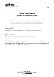
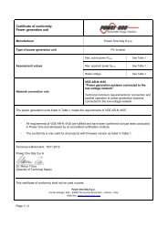
<strong>ZY7120</strong> <strong>20A</strong> <strong>DC</strong>-<strong>DC</strong> <strong>Intelligent</strong> <strong>POL</strong> <strong>Data</strong> <strong>Sheet</strong>3V to 13.2V Input 0.5V to 5.5V Output5. Typical Performance Characteristics5.1 Efficiency CurvesEfficiency, %969492908886848280787674Vout=0.5V Vout=1.2V Vout=2.5V720 2 4 6 8 10 12 14 16 18 20Output Current, AEfficiency, %949290888684828078767472Vout=1.2VVout=2.5V70Vout=3.3VVout=5.0V680 2 4 6 8 10 12 14 16 18 20Output Current, AFigure 4. Efficiency vs. Load. Vin=12V, Fsw=500kHzFigure 2. Efficiency vs. Load. Vin=3.3V, Fsw=500kHz95Efficiency, %9694929088868482807876747270Vout=0.5VVout=2.5VVout=1.2VVout=3.3V0 2 4 6 8 10 12 14 16 18 20Output Current, AFigure 3. Efficiency vs. Load. Vin=5V, Fsw=500kHzEfficiency, %908580757065Vin=3.3V Vin=5.0V Vin=12V600.5 1.5 2.5 3.5 4.5 5.5Output Voltage, VFigure 5. Efficiency vs. Output Voltage, Iout=<strong>20A</strong>,Fsw=500kHzZD-00194 Rev. 2.5, 01-Jul-10 www.power-one.com Page 8 of 34
<strong>ZY7120</strong> <strong>20A</strong> <strong>DC</strong>-<strong>DC</strong> <strong>Intelligent</strong> <strong>POL</strong> <strong>Data</strong> <strong>Sheet</strong>3V to 13.2V Input 0.5V to 5.5V Output9590908988858786Efficiency, %8075Efficiency, %85848370828165Vout=0.5V Vout=1.2V Vout=2.5V8079Fsw=500kHz Fsw=750kHz Fsw=1,000kHz603 4 5 6 7 8 9 10 11 12780 2 4 6 8 10 12 14 16 18 20Input Voltage, VOutput Current, AFigure 6. Efficiency vs. Input Voltage. Iout=<strong>20A</strong>, Fsw=500kHzFigure 8. Efficiency vs. Load. Vin=5V, Vout=1.2VEfficiency, %96959493929190Fsw=500kHz Fsw=750kHz Fsw=1,000kHz890 2 4 6 8 10 12 14 16 18 20Output Current, AEfficiency, %949392919089888786858483Fsw=500kHz Fsw=750kHz Fsw=1,000kHz820 2 4 6 8 10 12 14 16 18 20Output Current, AFigure 7. Efficiency vs. Load. Vin=3.3V, Vout=2.5VFigure 9. Efficiency vs. Load. Vin=12V, Vout=5VZD-00194 Rev. 2.5, 01-Jul-10 www.power-one.com Page 9 of 34
<strong>ZY7120</strong> <strong>20A</strong> <strong>DC</strong>-<strong>DC</strong> <strong>Intelligent</strong> <strong>POL</strong> <strong>Data</strong> <strong>Sheet</strong>3V to 13.2V Input 0.5V to 5.5V OutputEfficiency, %949392919089888786858483Vin=3.3V, Vout=2.5VVin=5V, Vout=1.2VVin=12V, Vout=5V82500 750 1000Switching Frequency, kHzFigure 10. Efficiency vs. Switching Frequency. Iout=<strong>20A</strong>Figure 12. Turn-On with Different Rising Slew Rates.Rising Slew Rates are Programmed as follows: V1-1V/ms, V2-0.5V/ms, V3-0.2V/ms.Vin=12V, Ch1 – V1, Ch2 – V2, Ch3 – V35.2 Turn-On CharacteristicsFigure 11. Tracking Turn-On. Rising Slew Rate isProgrammed at 0.5V/ms.Vin=12V, Ch1 – V1, Ch2 – V2, Ch3 – V3Figure 13. Sequenced Turn-On. Rising Slew Rate isProgrammed at 1V/ms. V2 Delay is 2ms, V3 delayis 4ms. Vin=12V, Ch1 – V1, Ch2 – V2, Ch3 – V3ZD-00194 Rev. 2.5, 01-Jul-10 www.power-one.com Page 10 of 34
<strong>ZY7120</strong> <strong>20A</strong> <strong>DC</strong>-<strong>DC</strong> <strong>Intelligent</strong> <strong>POL</strong> <strong>Data</strong> <strong>Sheet</strong>3V to 13.2V Input 0.5V to 5.5V Output5.3 Turn-Off CharacteristicsFigure 14. Turn On with Sequencing and Tracking. RisingSlew Rate Programmed at 0.2V/ms, V1 and V3delays are programmed at 20ms.Vin=12V, Ch1 – V1, Ch2 – V2, Ch3 – V3Figure 16. Tracking Turn-Off. Falling Slew Rate isProgrammed at 0.5V/ms.Vin=12V, Ch1 – V1, Ch2 – V2, Ch3 – V3Figure 15. Turn On into Prebiased Load. V3 is Prebiased byV2 via a Diode.Vin=12V, Ch1 – V1, Ch2 – V2, Ch3 – V3Figure 17. Turn-Off with Tracking and Sequencing. FallingSlew Rate is Programmed at 0.5V/ms.Vin=12V, Ch1 – V1, Ch2 – V2, Ch3 – V3ZD-00194 Rev. 2.5, 01-Jul-10 www.power-one.com Page 11 of 34
<strong>ZY7120</strong> <strong>20A</strong> <strong>DC</strong>-<strong>DC</strong> <strong>Intelligent</strong> <strong>POL</strong> <strong>Data</strong> <strong>Sheet</strong>3V to 13.2V Input 0.5V to 5.5V Output5.4 Transient ResponseThe pictures below show the deviation of the outputvoltage in response to the 50-100-50% step load at1A/μs. In all tests the <strong>ZY7120</strong> converters wereswitching at 1MHz and had 5x22μF and 5x47μFceramic capacitors connected across the outputpins. Bandwidth of the feedback loop wasprogrammed for faster transient response.Figure 20. Vin=5V, Vout=2.5V, BW~45kHzFigure 18. Vin=12V, Vout=5V, BW~40kHzFigure 21. Vin=5V, Vout=1V, BW~40kHzFigure 19. Vin=12V, Vout=1V, BW~35kHzFigure 22. Vin=3.3V, Vout=1V, BW~40kHzZD-00194 Rev. 2.5, 01-Jul-10 www.power-one.com Page 12 of 34
<strong>ZY7120</strong> <strong>20A</strong> <strong>DC</strong>-<strong>DC</strong> <strong>Intelligent</strong> <strong>POL</strong> <strong>Data</strong> <strong>Sheet</strong>3V to 13.2V Input 0.5V to 5.5V Output5.5 Thermal Derating Curves2018Output Current, A161412100 LFM 100 LFM 200 LFM 400 LFM 600 LFM835 45 55 65 75 85Temperature, 'CFigure 23. Thermal Derating Curves. Vin=13.2V, Vout=5.0V, Fsw=500kHz20Output Current, A19181716150 LFM 100 LFM 200 LFM 400 LFM 600 LFM65 70 75 80 85Temperature, 'CFigure 24. Thermal Derating Curves. Vin=5.0V, Vout=2.5V, Fsw=500kHzZD-00194 Rev. 2.5, 01-Jul-10 www.power-one.com Page 13 of 34
<strong>ZY7120</strong> <strong>20A</strong> <strong>DC</strong>-<strong>DC</strong> <strong>Intelligent</strong> <strong>POL</strong> <strong>Data</strong> <strong>Sheet</strong>3V to 13.2V Input 0.5V to 5.5V OutputFigure 26. Complete Schematic of the Application Shown in Figure 25. Intermediate Bus Voltage is from 4.75V to 13.2V.ZD-00194 Rev. 2.5, 01-Jul-10 www.power-one.com Page 15 of 34
<strong>ZY7120</strong> <strong>20A</strong> <strong>DC</strong>-<strong>DC</strong> <strong>Intelligent</strong> <strong>POL</strong> <strong>Data</strong> <strong>Sheet</strong>3V to 13.2V Input 0.5V to 5.5V Output7. Pin Assignments and DescriptionPinNamePinNumberPinTypeBufferTypePin DescriptionVLDO 1 P Low Voltage DropoutNotesConnect to an external voltage source higher than4.75V, if V IN
<strong>ZY7120</strong> <strong>20A</strong> <strong>DC</strong>-<strong>DC</strong> <strong>Intelligent</strong> <strong>POL</strong> <strong>Data</strong> <strong>Sheet</strong>3V to 13.2V Input 0.5V to 5.5V Output8. Programmable FeaturesPerformance parameters of <strong>ZY7120</strong> <strong>POL</strong> converterscan be programmed via the industry standard I 2 Ccommunication bus without replacing anycomponents or rewiring PCB traces. Eachparameter has a default value stored in the volatilememory registers detailed in Table 1. The setupregisters 00h through 14h are programmed at thesystem power-up. When the user programs newperformance parameters, the values in the registersare overwritten. Upon removal of the input voltage,the default values are restored.Table 1. <strong>ZY7120</strong> Memory RegistersRegister Content AddressPC1 Protection Configuration 1 00hPC2 Protection Configuration 2 01hPC3 Protection Configuration 3 02hDON Turn-On Delay 05hDOF Turn-Off Delay 06hTC Tracking Configuration 03hINT Interleave Configuration and 04hFrequency SelectionRUN RUN Register 15hST Status Register 16hVOS Output Voltage Setpoint 07hCLS Current Limit Setpoint 08h<strong>DC</strong>L Duty Cycle Limit 09hB1 Dig Controller Denominator z -1 0AhCoefficientB2 Dig Controller Denominator z -2 0BhCoefficientB3 Dig Controller Denominator z -3 0ChCoefficientC0L Dig Controller Numerator z 0 0DhCoefficient, Low ByteC0H Dig Controller Numerator z 0 0EhCoefficient, High ByteC1L Dig Controller Numerator z -1 0FhCoefficient, Low ByteC1H Dig Controller Numerator z -1 10hCoefficient, High ByteC2L Dig Controller Numerator z -2 11hCoefficient, Low ByteC2H Dig Controller Numerator z -2 12hCoefficient, High ByteC3L Dig Controller Numerator z -3 13hCoefficient, High ByteC3H Dig Controller Numerator z -3 14hCoefficient, Low ByteVOM Output Voltage Monitoring 17hIOM Output Current Monitoring 18hTMP Temperature Monitoring 19h<strong>ZY7120</strong> converters can be programmed using theGraphical User Interface or directly via the I 2 C bus byusing high and low level commands as described inthe ‘”DPM Programming Manual”.<strong>ZY7120</strong> parameters can be reprogrammed at anytime during the system operation and service exceptfor the digital filter coefficients, the switchingfrequency and the duty cycle limit, that can only bechanged when the <strong>POL</strong> is turned off.8.1 Output VoltageThe output voltage can be programmed in the GUIOutput Configuration window shown in the Figure 27or directly via the I 2 C bus by writing into the VOSregister shown in Figure 28.Figure 27. Output Configuration WindowR/W-0 R/W-0 R/W-0 R/W-0 R/W-0 R/W-0 R/W-0 R/W-0VOS7 VOS6 VOS5 VOS4 VOS3 VOS2 VOS1 VOS0Bit 7 Bit 0Bit 7:0 VOS[7:0], Output voltage setting00h: corresponds to 0.5000V01h: corresponds to 0.5125V…77h: corresponds to 1.9875V78h: corresponds to 2.0000V79h: corresponds to 2.025V…F9h: corresponds to 5.225VFAh: corresponds to 5.250VFBh: corresponds to 5.300V…FFh: corresponds to 5.500VR = Readable bitW = Writable bitU = Unimplemented bit,read as ‘0’- n = Value at POR resetFigure 28. Output Voltage Setpoint Register VOSZD-00194 Rev. 2.5, 01-Jul-10 www.power-one.com Page 17 of 34
<strong>ZY7120</strong> <strong>20A</strong> <strong>DC</strong>-<strong>DC</strong> <strong>Intelligent</strong> <strong>POL</strong> <strong>Data</strong> <strong>Sheet</strong>3V to 13.2V Input 0.5V to 5.5V Output8.1.1 Output Voltage SetpointThe output voltage programming range is from 0.5Vto 5.5V. Within this range, there are 256 predefinedvoltage setpoints. To improve resolution of theoutput voltage settings, the voltage range is dividedinto three sub-ranges as shown in Table 2.Table 2. Output Voltage Adjustment ResolutionV OUT MIN , V V OUT MAX , V Resolution, mV0.500 2.000 12.52.025 5.25 255.3 5.5 508.1.2 Output Voltage MarginingIf the output voltage needs to be varied by a certainpercentage, the margining function can be utilized.The margining can be programmed in the GUIOutput Configuration window or directly via the I 2 Cbus using high level commands as described in the‘”DPM Programming Manual”.In order to properly margin <strong>POL</strong>s that are connectedin parallel, the <strong>POL</strong>s must be members of one of theParallel Buses. Refer to the GUI SystemConfiguration Window shown in Figure 55.8.1.3 Optimal Voltage PositioningOptimal voltage positioning increases the voltageregulation window by properly positioning the outputvoltage setpoint. Positioning is determined by theload regulation that can be programmed in the GUIOutput Configuration window shown in Figure 27 ordirectly via the I 2 C bus by writing into the CLSregister shown in Figure 38.Figure 29 illustrates optimal voltage positioningconcept. If no load regulation is programmed, theheadroom (voltage differential between the outputvoltage setpoint and a regulation limit) isapproximately half of the voltage regulation window.When load regulation is programmed, the outputvoltage will decrease as the output currentincreases, so the VI characteristic will have anegative slope. Therefore, by properly selecting theoperating point, it is possible to increase theheadroom as shown in the picture.Upper RegulationLimitLower RegulationLimitV OUTI OUTVI Curve WithoutLightLoadOperatingPointHeadroom withoutLoad RegulationHeadroom withLoad RegulationVI Curve WithLoad RegulationLoad RegulationHeavyLoadFigure 29. Concept of Optimal Voltage PositioningIncreased headroom allows tolerating larger voltagedeviations. For example, the step load change fromlight to heavy load will cause the output voltage todrop. If the optimal voltage positioning is utilized, theoutput voltage will stay within the regulation window.Otherwise, the output voltage will drop below thelower regulation limit. To compensate for the voltagedrop external output capacitance will need to beadded, thus increasing cost and complexity of thesystem.The effect of optimal voltage positioning is shown inFigure 30 and Figure 31. In this case, switchingoutput load causes large peak-to-peak deviation ofthe output voltage. By programming load regulation,the peak to peak deviation is dramatically reduced.Figure 30. Transient Response without Optimal VoltagePositioningZD-00194 Rev. 2.5, 01-Jul-10 www.power-one.com Page 18 of 34
<strong>ZY7120</strong> <strong>20A</strong> <strong>DC</strong>-<strong>DC</strong> <strong>Intelligent</strong> <strong>POL</strong> <strong>Data</strong> <strong>Sheet</strong>3V to 13.2V Input 0.5V to 5.5V OutputR/W-0 R/W-0 R/W-0 R/W-0 R/W-0 R/W-0 R/W-0 R/W-0DON7 DON6 DON5 DON4 DON3 DON2 DON1 DON0Bit 7 Bit 0Bit 7:0 DON[7:0]: Turn-on delay time00h: corresponds to 0ms delay after turn-on command has occurred…FFh: corresponds to 255ms delay after turn-on command has occurredFigure 33. Turn-On Delay Register DON8.2.2 Turn-Off DelayU U R/W-0 R/W-0 R/W-0 R/W-0 R/W-0 R/W-0--- --- DOF5 DOF4 DOF3 DOF2 DOF1 DOF0Bit 7 Bit 0Figure 31. Transient Response with Optimal VoltagePositioning8.2 Sequencing and TrackingTurn-on delay, turn-off delay, and rising and fallingoutput voltage slew rates can be programmed in theGUI Sequencing/Tracking window shown in Figure32 or directly via the I 2 C bus by writing into the DON,DOF, and TC registers, respectively. The registersare shown in Figure 33, Figure 34, and Figure 36.Bit 7:6 Unimplemented, read as ‘0’Bit 5:0 DOF[5:0]: Turn-off delay time00h: corresponds to 0ms delay after turn-off command has occurred…3Fh: corresponds to 63ms delay after turn-off command has occurredFigure 34. Turn-Off Delay Register DOFTurn-off delay is defined as an interval from theapplication of the Turn-Off command until the outputvoltage reaches zero (if the falling slew rate isprogrammed) or until both high side and low sideswitches are turned off (if the slew rate is notprogrammed). Therefore, for the slew rate controlledturn-off the ramp-down time is included in the turn-offdelay as shown in Figure 35.User programmed turn-off delay, T DFTurn-OffCommandInternalramp-downcommandV OUTCalculateddelay T DRamp-down time, T FFalling slewrate dV F /dTFigure 32. Sequencing/Tracking Window8.2.1 Turn-On DelayTurn-on delay is defined as an interval from theapplication of the Turn-On command until the outputvoltage starts ramping up.TimeFigure 35. Relationship between Turn-Off Delay and FallingSlew RateAs it can be seen from the figure, the internallycalculated delay T D is determined by the equationbelow.VOUTTD TDF ,dVFdTFor proper operation T D shall be greater than zero.The appropriate value of the turn-off delay needs tobe programmed to satisfy the condition.ZD-00194 Rev. 2.5, 01-Jul-10 www.power-one.com Page 19 of 34
<strong>ZY7120</strong> <strong>20A</strong> <strong>DC</strong>-<strong>DC</strong> <strong>Intelligent</strong> <strong>POL</strong> <strong>Data</strong> <strong>Sheet</strong>3V to 13.2V Input 0.5V to 5.5V OutputIf the falling slew rate control is not utilized, the turnoffdelay only determines an interval from theapplication of the Turn-Off command until both highside and low side switches are turned off. In thiscase, the output voltage ramp-down process isdetermined by load parameters.8.2.3 Rising and Falling Slew RatesThe output voltage tracking is accomplished byprogramming the rising and falling slew rates of theoutput voltage. To achieve programmed slew rates,the output voltage is being changed in 12.5mV stepswhere duration of each step determines the slewrate. For example, ramping up a 1.0V output with aslew rate of 0.5V/ms will require 80 steps duration of25μs each.Duration of each voltage step is calculated bydividing the master clock frequency generated by theDPM. Since all <strong>POL</strong>s in the system aresynchronized to the master clock, the matching ofvoltage slew rates of different outputs is veryaccurate as it can be seen in Figure 11 and Figure16.During the turn on process, a <strong>POL</strong> not only deliverscurrent required by the load (I LOAD ), but also chargesthe load capacitance. The charging current can bedetermined from the equation below:ICHG CLOADdVWhere, C LOAD is load capacitance, dV R /dt is risingvoltage slew rate, and I CHG is charging current.When selecting the rising slew rate, a user needs toensure thatILOAD ICHG IROCPWhere I OCP is the overcurrent protection threshold ofthe <strong>ZY7120</strong>. If the condition is not met, then theovercurrent protection will be triggered during theturn-on process. To avoid this, dV R /dt and theovercurrent protection threshold should beprogrammed to meet the condition above.dtU R/W-0 R/W-0 R/W-0 R/W-1 R/W-0 R/W-0 R/W-0--- R2 R1 R0 SC F2 F1 F0Bit 7 Bit 0Bit 7 Unimplemented , read as ‘0’Bit 6:4Bit 3Bit 2:0R[2:0]: Value of Vo rising slope0: corresponds to 0.1V/ms (default)1: corresponds to 0.2V/ms2: corresponds to 0.5V/ms3: corresponds to 1.0V/ms4: corresponds to 2.0V/ms5: corresponds to 5.0V/ms6: corresponds to 8.3V/ms7: corresponds to 8.3V/msSC, Slew rate control at turn-off0: Slew rate control is disabled1: Slew rate control is enabledF[2:0]: Value of Vo falling slope0: corresponds to -0.1V/ms (default)1: corresponds to -0.2V/ms2: corresponds to -0.5V/ms3: corresponds to -1.0V/ms4: corresponds to -2.0V/ms5: corresponds to -5.0V/ms6: corresponds to –8.3V/ms7: corresponds to –8.3V/msR = Readable bitW = Writable bitU = Unimplemented bit,read as ‘0’-n =Value at POR resetFigure 36. Tracking Configuration Register TC8.3 Protections<strong>ZY7120</strong> Series converters have a comprehensive setof programmable protections. The set includes theoutput over- and undervoltage protections,overcurrent protection, overtemperature protection,tracking protection, overtemperature warning, and<strong>Power</strong> Good signal. Status of protections is stored inthe ST register shown in Figure 37.R-1 R-0 R-1 R-1 R-1 R-1 R-1 R-1TP PG TR OT OC UV OV PVBit 7 Bit 0Bit 7Bit 6Bit 5Bit 4Bit 3Bit 2Bit 1Bit 0TP: Temperature WarningPG: <strong>Power</strong> Good WarningTR: Tracking FaultOT: Overtemperature FaultOC: Overcurrent FaultUV: Undervoltage FaultOV: Overvoltage ErrorPV: Phase Voltage ErrorNote:- An activated warning/fault/error is encoded as ‘0’R = Readable bitW = Writable bitU = Unimplemented bit,read as ‘0’-n =Value at POR resetFigure 37. Protection Status Register STThresholds of overcurrent, over- and undervoltageprotections, and <strong>Power</strong> Good limits can beprogrammed in the GUI Output Configurationwindow or directly via the I 2 C bus by writing into theCLS and PC2 registers shown in Figure 38 andFigure 39.ZD-00194 Rev. 2.5, 01-Jul-10 www.power-one.com Page 20 of 34
<strong>ZY7120</strong> <strong>20A</strong> <strong>DC</strong>-<strong>DC</strong> <strong>Intelligent</strong> <strong>POL</strong> <strong>Data</strong> <strong>Sheet</strong>3V to 13.2V Input 0.5V to 5.5V OutputR/W-0 R/W-0 R/W-0 R/W-1 R/W-1 R/W-0 R/W-1 R/W-1LR2 LR1 LR0 TCE CLS3 CLS2 CLS1 CLS0Bit 7 Bit 0Bit 7:5 LR[2:0], Load regulation configuration000: 0 V/A/Ohm001: 0.39 V/A/Ohm010: 0.78 V/A/Ohm011: 1.18 V/A/Ohm100: 1.57 V/A/Ohm101: 1.96 V/A/Ohm110: 2.35 V/A/Ohm111: 2.75 V/A/OhmBit 4 TCE, Temperature compensation enable0: disabled1: enabledBit 3:0 CLS[3:0], Current limit setting0h: corresponds to 37%1h: corresponds to 47%…Bh: corresponds to 140%Values higher than Bh are translated to Bh (140%)R = Readable bitW = Writable bitU = Unimplemented bit,read as ‘0’- n = Value at POR resetFigure 38. Current Limit Setpoint Register CLSU U U R/W-0 R/W-1 R/W-0 R/W-0 R/W-0--- --- --- PGLL OVPL1 OVPL0 UVPL1 UVPL0Bit 7 Bit 0Bit 7:5 Unimplemented, read as ‘0’Bit 4 PGLL: Set <strong>Power</strong> Good Low Level1 = 95% of Vo0 = 90% of Vo (Default)Bit 3:2 OVPL[1:0]: Set Over Voltage ProtectionLevel00 = 110% of Vo01 = 120% of Vo10 = 130% of Vo (Default)11 = 130% of VoR = Readable bitW = Writable bitU = Unimplemented bit,read as ‘0’- n = Value at POR resetBit 1:0 UVPL[1:0]: Set Under Voltage Protection Level00 = 75% of Vo (Default)01 = 80% of Vo10 = 85% of VoFigure 39. Protection Configuration Register PC2Note that the overvoltage and undervoltageprotection thresholds and <strong>Power</strong> Good limits aredefined as percentages of the output voltage.Therefore, the absolute levels of the thresholdschange when the output voltage setpoint is changedeither by output voltage adjustment or by margining.In addition, a user can change type of protections(latching or non-latching) or disable certainprotections. These settings are programmed in theGUI Fault Management window shown in Figure 40or directly via the I 2 C by writing into the PC1 registershown in Figure 41.Figure 40. Fault Management WindowR/W-0 R/W-1 R/W-0 R/W-0 R/W-0 R/W-0 R/W-1 R/W-1TRE PVE TRP OTP OCP UVP OVP PVPBit 7 Bit 0Bit 7Bit 6Bit 5Bit 4Bit 3Bit 2Bit 1Bit 0TRE: Tracking fault enable1 = enabled0 = disabledPVE: Phase voltage error enable1 = enabled0 = disabledTRP: Tracking fault protection1 = latching0 = non latchingOTP: Overtemperature protection configuration1 = latching0 = non latchingOCP: Overcurrent protection configuration1 = latching0 = non latchingUVP: Undervoltage protection configuration1 = latching0 = non latchingOVP: Overvoltage protection configuration1 = latching0 = non latchingPVP: Phase Voltage Protection1 = latching0 = non latchingR = Readable bitW = Writable bitU = Unimplemented bit,read as ‘0’-n =Value at POR resetFigure 41. Protection Configuration Register PC1If the non-latching protection is selected, a <strong>POL</strong> willattempt to restart every 130ms until the conditionthat triggered the protection is removed. Whenrestarting, the output voltages follow tracking andsequencing settings.If the latching type is selected, a <strong>POL</strong> will turn off andstay off. The <strong>POL</strong> can be turned on after 130ms, ifthe condition that caused the fault is removed andthe respective bit in the ST register was cleared, orthe Turn On command was recycled, or the inputvoltage was recycled.ZD-00194 Rev. 2.5, 01-Jul-10 www.power-one.com Page 21 of 34
<strong>ZY7120</strong> <strong>20A</strong> <strong>DC</strong>-<strong>DC</strong> <strong>Intelligent</strong> <strong>POL</strong> <strong>Data</strong> <strong>Sheet</strong>3V to 13.2V Input 0.5V to 5.5V OutputAll protections can be classified into three groupsbased on their effect on system operation: warnings,faults, and errors.8.3.1 WarningsThis group includes Overtemperature Warning and<strong>Power</strong> Good Signal. The warnings do not turn off<strong>POL</strong>s but rather generate signals that can betransmitted to a host controller via the I 2 C bus.8.3.1.1 Overtemperature WarningThe Overtemperature Warning is generated whentemperature of the controller exceeds 120°C. TheOvertemperature Warning changes the PT bit of thestatus register ST to 0 and sends the signal to theDPM. Reporting is enabled in the GUI FaultManagement window or directly via the I 2 C by writinginto the PC3 register shown in Figure 43. When thetemperature falls below 117°C, the PT bit is clearedand the Overtemperature Warning is removed.8.3.1.2 <strong>Power</strong> Good<strong>Power</strong> Good is an open collector output that is pulledlow, if the output voltage is outside of the <strong>Power</strong>Good window. The window is formed by the <strong>Power</strong>Good High threshold that is equal to 110% of theoutput voltage and the <strong>Power</strong> Good Low thresholdthat can be programmed at 90 or 95% of the outputvoltage.The <strong>Power</strong> Good protection is only enabled after theoutput voltage reaches its steady state level. ThePGOOD pin is pulled low during transitions of theoutput voltage from one level to other as shown inFigure 42.The <strong>Power</strong> Good Warning pulls the <strong>Power</strong> Good pinlow and changes the PG bit of the status register STto 0. It sends the signal to the DPM, if the reportingis enabled. When the output voltage returns withinthe <strong>Power</strong> Good window, the PG pin is pulled high,the PG bit is cleared and the <strong>Power</strong> Good Warning isremoved. The <strong>Power</strong> Good pin can also be pulledlow by an external circuit to initiate the <strong>Power</strong> GoodWarning.Note: To retrieve status information, Status Monitoring in the GUI<strong>POL</strong> Group Configuration Window should be enabled (referto Digital <strong>Power</strong> Manager <strong>Data</strong> <strong>Sheet</strong>). The DPM willretrieve the status information from each <strong>POL</strong> on acontinuous basis.8.3.2 FaultsThis group includes overcurrent, overtemperature,undervoltage, and tracking protections. Triggeringany protection in this group will turn off the <strong>POL</strong>.8.3.2.1 Overcurrent ProtectionOvercurrent protection is active whenever the outputvoltage of the <strong>POL</strong> exceeds the prebias voltage (ifany). When the output current reaches the OCthreshold, the output voltage will start decreasing.As soon as the output voltage decreases below theundervoltage protection threshold, the OC faultsignal is generated, the <strong>POL</strong> turns off and the OC bitin the register ST is changed to 0. Both high sideand low side switches of the <strong>POL</strong> are turned offinstantly (fast turn-off).The temperature compensation is added to keep theOC threshold approximately constant attemperatures above room temperature. Note thatthe temperature compensation can be disabled inthe GUI Output Configuration window or directly viathe I 2 C by writing into the CLS register. However, itis recommended to keep the temperaturecompensation enabled.8.3.2.2 Undervoltage ProtectionThe undervoltage protection is only active duringsteady state operation of the <strong>POL</strong> to preventnuisance tripping. If the output voltage decreasesbelow the UV threshold and there is no OC fault, theUV fault signal is generated, the <strong>POL</strong> turns off, andthe UV bit in the register ST is changed to 0. Theoutput voltage is ramped down according tosequencing and tracking settings (regular turn-off).8.3.2.3 Overtemperature ProtectionOvertemperature protection is active whenever the<strong>POL</strong> is powered up. If temperature of the controllerexceeds 130°C, the OT fault is generated, <strong>POL</strong> turnsoff, and the OT bit in the register ST is changed to 0.The output voltage is ramped down according tosequencing and tracking settings (regular turn-off).If non-latching OTP is programmed, the <strong>POL</strong> willrestart as soon as the temperature of the controllerdecreases below the Overtemperature Warningthreshold of 120°C.ZD-00194 Rev. 2.5, 01-Jul-10 www.power-one.com Page 22 of 34
<strong>ZY7120</strong> <strong>20A</strong> <strong>DC</strong>-<strong>DC</strong> <strong>Intelligent</strong> <strong>POL</strong> <strong>Data</strong> <strong>Sheet</strong>3V to 13.2V Input 0.5V to 5.5V Output8.3.2.4 Tracking ProtectionTracking protection is active only when the outputvoltage is ramping up. The purpose of the protectionis to ensure that the voltage differential betweenmultiple rails being tracked does not exceed 250mV.This protection eliminates the need for externalclamping diodes between different voltage railswhich are frequently recommended by ASICmanufacturers.When the tracking protection is enabled, the <strong>POL</strong>continuously compares actual value of the outputvoltage to its programmed value as defined by theoutput voltage and its rising slew rate. If absolutevalue of the difference exceeds 250mV, the trackingfault signal is generated, the <strong>POL</strong> turns off, and theTR bit in the register ST is changed to 0. Both highside and low side switches of the <strong>POL</strong> are turned offinstantly (fast turn-off).The tracking protection can be disabled, if itcontradicts requirements of a particular system (forexample turning into high capacitive load whererising slew rate is not important). It can be disabledin the GUI Fault Management window or directly viathe I 2 C bus by writing into the PC1 register.Vo1Enable command 0OTP continuously enabled1OCP enabled 0<strong>Power</strong> GoodSignal10OVP ThresholdOVP Threshold1.0Vprebiased outputTrackingThresholdsPG High=110%V OUTOutput VoltagePG Low ThresholdUVP ThresholdOVP ThresholdPG High=110%V OUTOutput VoltagePG Low ThresholdUVP ThresholdPG High=110%V OUTOutput VoltagePG Low ThresholdUVP ThresholdTimeFigure 42. Protections Enable Conditions8.3.3 ErrorsThe group includes overvoltage protection and thephase voltage error. The phase voltage error is notavailable in <strong>ZY7120</strong>.8.3.3.1 Overvoltage ProtectionThe overvoltage protection is active whenever theoutput voltage of the <strong>POL</strong> exceeds the pre-biasvoltage (if any). If the output voltage exceeds theovervoltage protection threshold, the overvoltageerror signal is generated, the <strong>POL</strong> turns off, and theOV bit in the register ST is changed to 0. The highside switch is turned off instantly, and simultaneouslythe low side switch is turned on to ensure reliableprotection of sensitive loads. The low side switchprovides low impedance path to quickly dissipateenergy stored in the output filter and achieveeffective voltage limitation.The OV threshold can be programmed from 110% to130% of the output voltage setpoint, but not lowerthan 1.0V.8.3.4 Faults and Errors PropagationThe feature adds flexibility to the fault managementscheme by giving users control over propagation offault signals within and outside of the system. Thepropagation means that a fault in one <strong>POL</strong> can beprogrammed to turn off other <strong>POL</strong>s and devices inthe system, even if they are not directly affected bythe fault.ZD-00194 Rev. 2.5, 01-Jul-10 www.power-one.com Page 23 of 34
<strong>ZY7120</strong> <strong>20A</strong> <strong>DC</strong>-<strong>DC</strong> <strong>Intelligent</strong> <strong>POL</strong> <strong>Data</strong> <strong>Sheet</strong>3V to 13.2V Input 0.5V to 5.5V Output8.3.4.1 Grouping of <strong>POL</strong>sZ-Series <strong>POL</strong>s can be arranged in several groups tosimplify fault management. A group of <strong>POL</strong>s isdefined as a number of <strong>POL</strong>s with interconnectedOK pins. A group can include from 1 to 32 <strong>POL</strong>s. Iffault propagation within a group is desired, thepropagation bit needs to be checked in the GUI FaultManagement Window. The parameters can also beprogrammed directly via the I 2 C bus by writing intothe PC3 register shown in Figure 43.When propagation is enabled, the faulty <strong>POL</strong> pulls itsOK pin low. A low OK line initiates turn-off of other<strong>POL</strong>s in the group.R/W-0 R/W-0 R/W-1 R/W-1 R/W-1 R/W-1 R/W-1 R/W-1PTM PGM TRP OTP OCP UVP OVP PVPBit 7 Bit 0Bit 7 PTM: Temperature warning Message1 = enabled0 = disabledBit 6 PGM: <strong>Power</strong> good message1 = enabled0 = disabledBit 5 TRP : Tracking fault propagation1 = enabled0 = disabledBit 4 OTP: Overtemperature fault propagation1 = enabled0 = disabledBit 3 OCP: Overcurrent fault propagation1 = enabled0 = disabledBit 2 UVP: Undervoltage fault propagation1 = enabled0 = disabledBit 1 OVP: Overvoltage error propagation1 = enabled0 = disabledBit 0 PVP : Phase voltage error propagation1 = enabled0 = disabledR = Readable bitW = Writable bitU = Unimplemented bit,read as ‘0’-n = Value at POR resetFigure 43. Protection Configuration Register PC3In addition, the OK lines can be connected to theDPM to facilitate propagation of faults and errorsbetween groups. <strong>One</strong> DPM can control up to 4independent groups. To enable fault propagationbetween groups, the respective bit needs to bechecked in the GUI Fault and Error Propagationwindow shown in Figure 44.Figure 44. Fault and Error Propagation WindowIn this case low OK line will signal DPM to pull otherOK lines low to initiate shutdown of other <strong>POL</strong>s asprogrammed in the GUI Fault and Error Propagationwindow. If an error is propagated, the DPM can alsogenerate commands to turn off a front end (a <strong>DC</strong>-<strong>DC</strong>converter generating the intermediate bus voltage)and trigger an optional crowbar protection toaccelerate removal of the IBV voltage.8.3.4.2 Propagation ProcessPropagation of a fault (OCP, UVP, OTP, and TRP)initiates regular turn-off of other <strong>POL</strong>s. The faulty<strong>POL</strong> in this case performs either the regular or thefast turn-off depending on a specific fault asdescribed in section 8.3.2.Propagation of an error initiates fast turn-off of other<strong>POL</strong>s. The faulty <strong>POL</strong> performs the fast turn-off andturns on its low side switch.Example of the fault propagation is shown in Figure45 - Figure 46. In this three-output system (refer tothe block diagram in Figure 25), the <strong>POL</strong> poweringthe output V3 (Ch 1 in the picture) encounters theundervoltage fault after the turn-on. When the faultpropagation is not enabled, the <strong>POL</strong> turns off andgenerates the UV fault signal. Because the UV faulttriggers the regular turn off, the <strong>POL</strong> meets its turnoffdelay and falling slew rate settings during theturn-ff process as shown in Figure 45. Since the UVfault is programmed to be non-latching, the <strong>POL</strong> willattempt to restart every 130ms, repeating theprocess described above until the condition causingthe undervoltage is removed.If the fault propagation between groups is enabled,the <strong>POL</strong> powering the output V3 pulls its OK line lowand the DPM propagates the signal to the <strong>POL</strong>powering the output V1 that belongs to other group.ZD-00194 Rev. 2.5, 01-Jul-10 www.power-one.com Page 24 of 34
<strong>ZY7120</strong> <strong>20A</strong> <strong>DC</strong>-<strong>DC</strong> <strong>Intelligent</strong> <strong>POL</strong> <strong>Data</strong> <strong>Sheet</strong>3V to 13.2V Input 0.5V to 5.5V OutputThe <strong>POL</strong> powering the output V1 (Ch3 in the picture)executes the regular turn-off. Since both V1 and V3have the same delay and slew rate settings they willcontinue to turn off and on synchronously every130ms as shown in Figure 46 until the conditioncausing the undervoltage is removed. The <strong>POL</strong>powering the output V2 continues to ramp up until itreaches its steady state level.130ms is the interval from the instant of time whenthe output voltage ramps down to zero until theoutput voltage starts to ramp up again. Therefore,the 130ms hiccup interval is guaranteed regardlessof the turn-off delay setting.Figure 46. Turn-On into UVP on V3. The UV Fault IsProgrammed To Be Non-Latching and PropagateFrom Group C to Group A. Ch1 – V3 (Group C),Ch2 – V2, Ch3 – V1 (Group A)Summary of protections, their parameters andfeatures are shown in Table 3Figure 45. Turn-On into UVP on V3. The UV Fault IsProgrammed To Be Non-Latching. Ch1 – V3(Group C), Ch2 – V2, Ch3 – V1 (Group A)Table 3. Summary of Protections Parameters and FeaturesCode Name Type When Active TurnOffPT TemperatureWarningLow SideSwitchPropagationDisableWarning Whenever V IN is applied No N/A Sends signal to NoDPMPG <strong>Power</strong> Good Warning During steady state No N/A Sends signal to NoDPMTR Tracking Fault During ramp up Fast Off Regular turn off YesOT Overtemperature Fault Whenever V IN is applied Regular Off Regular turn off NoOC Overcurrent Fault When V OUT exceeds prebias Fast Off Regular turn off NoUV Undervoltage Fault During steady state Regular Off Regular turn off NoOV Overvoltage Error When V OUT exceeds prebias Fast On Fast turn off NoZD-00194 Rev. 2.5, 01-Jul-10 www.power-one.com Page 25 of 34
<strong>ZY7120</strong> <strong>20A</strong> <strong>DC</strong>-<strong>DC</strong> <strong>Intelligent</strong> <strong>POL</strong> <strong>Data</strong> <strong>Sheet</strong>3V to 13.2V Input 0.5V to 5.5V Output8.4 PWM ParametersZ-Series <strong>POL</strong>s utilize the digital PWM controller.The controller enables users to program most of thePWM performance parameters, such as switchingfrequency, interleave, duty cycle, and feedback loopcompensation.8.4.1 Switching FrequencyThe switching frequency can be programmed in theGUI PWM Controller window shown in Figure 47 ordirectly via the I 2 C bus by writing into the INT registershown in Figure 48. Note that the content of theregister can be changed only when the <strong>POL</strong> isturned off.Switching actions of all <strong>POL</strong>s connected to the SDline are synchronized to the master clock generatedby the DPM. Each <strong>POL</strong> is equipped with a PLL anda frequency divider so they can operate at multiples(including fractional) of the master clock frequencyas programmed by a user. The <strong>POL</strong> converters canoperate at 500 kHz, 750 kHz, and 1 MHz. Althoughsynchronized, switching frequencies of different<strong>POL</strong>s are independent of each other. It ispermissible to mix <strong>POL</strong>s operating at differentfrequencies in one system. It allows optimizingefficiency and transient response of each <strong>POL</strong> in thesystem individually.R/W-0 R/W-0 R/W-0 R/W-0 1) R/W-0 1) R/W-0 1) R/W-0 1) R/W-0 1)FRQ2 FRQ1 FRQ0 INT4 INT3 INT2 INT1 INT0Bit 7 Bit 0Bit 7:5FRQ[2:0] : PWM Frequency Selection000: 500kHz001: 750kHz010: 1000lHz011: 1250kHz100: 1250kHz101: 1500kHz110: 1750kHz111: 2000kHzR = Readable bitW = Writable bitU = Unimplemented bit,read as ‘0’-n =Value at POR resetBit 4:0 INT[4:0] : Interleave position00h: Ton starts with 0.0° Phase lag to SD Line01h: Ton starts wi th 11.25° Phase lag to SD Line02h: Ton starts with 22.50° Phase lag to SD Line…1Fh: Ton starts with 348.75° Phase lag to SD Line1) Initial value depends on the state of the Interleave Mode ( IM) Input:IM=Open: At POR reset the 5 corresponding ADDRESS bits are loadedIM=Low: At POR reset a 0 is loadedFigure 48. Interleave Configuration Register INT8.4.2 InterleaveInterleave is defined as a phase delay between thesynchronizing slope of the master clock on the SDpin and PWM signal of a <strong>POL</strong>. The interleave canbe programmed in the GUI PWM Controller windowor directly via the I 2 C bus by writing into the INTregister.Every <strong>POL</strong> generates switching noise. If nointerleave is programmed, all <strong>POL</strong>s in the systemswitch simultaneously and noise reflected to theinput source from all <strong>POL</strong>s is added together asshown in Figure 49.Figure 47. PWM Controller WindowFigure 49. Input Voltage Noise, No InterleaveZD-00194 Rev. 2.5, 01-Jul-10 www.power-one.com Page 26 of 34
<strong>ZY7120</strong> <strong>20A</strong> <strong>DC</strong>-<strong>DC</strong> <strong>Intelligent</strong> <strong>POL</strong> <strong>Data</strong> <strong>Sheet</strong>3V to 13.2V Input 0.5V to 5.5V OutputFigure 50 shows the input voltage noise of the threeoutputsystem with programmed interleave. Insteadof all three <strong>POL</strong>s switching at the same time as inthe previous example, the <strong>POL</strong>s V1, V2, and V3switch at 67.5°, 180°, and 303.75°, respectively.Noise is spread evenly across the switching cycleresulting in more than 1.5 times reduction. Toachieve similar noise reduction without the interleavewill require the addition of an external LC filter.Figure 52. Output Voltage Noise, Full Load, 180 InterleaveFigure 50. Input Voltage Noise with InterleaveSimilar noise reduction can be achieved on theoutput of <strong>POL</strong>s connected in parallel. Figure 51 andFigure 52 show the output noise of two <strong>ZY7120</strong>sconnected in parallel without and with 180°interleave, respectively. Resulting noise reduction ismore than 2 times and is equivalent to doublingswitching frequency or adding extra capacitance onthe output of the <strong>POL</strong>s.The <strong>ZY7120</strong> interleave feature is similar to that ofmultiphase converters, however, unlike in the case ofmultiphase converters, interleave does not have tobe equal to 360/N, where N is the number of <strong>POL</strong>s ina system. <strong>ZY7120</strong> interleave is independent of thenumber of <strong>POL</strong>s in a system and is fullyprogrammable in 11.25 steps. It allows maximumoutput noise reduction by intelligently spreadingswitching energy.Note: Due to noise sensitivity issues that may occur in limitedcases, it is recommended to avoid phase lag settings of112.5 and 123.75 degrees, otherwise false PG and/or OVindications may occur.8.4.3 Duty Cycle LimitThe <strong>ZY7120</strong> is a step-down converter therefore V OUTis always less than V IN . The relationship betweenthe two parameters is characterized by the dutycycle and can be estimated from the followingequation:VOUT<strong>DC</strong> ,VIN.MINWhere, <strong>DC</strong> is the duty cycle, V OUT is the requiredmaximum output voltage (including margining),V IN.MIN is the minimum input voltage.Figure 51. Output Voltage Noise, Full Load, No InterleaveIt is good practice to limit the maximum duty cycle ofthe PWM controller to a somewhat higher valuecompared to the steady-state duty cycle asexpressed by the above equation. This will furtherprotect the output from excessive voltages. The dutycycle limit can be programmed in the GUI PWMController window or directly via the I 2 C bus bywriting into the <strong>DC</strong>L register shown in Figure 53.ZD-00194 Rev. 2.5, 01-Jul-10 www.power-one.com Page 27 of 34
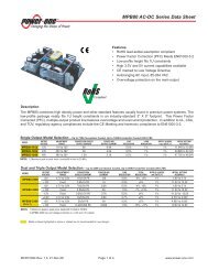
<strong>ZY7120</strong> <strong>20A</strong> <strong>DC</strong>-<strong>DC</strong> <strong>Intelligent</strong> <strong>POL</strong> <strong>Data</strong> <strong>Sheet</strong>3V to 13.2V Input 0.5V to 5.5V OutputR/W-1 R/W-1 R/W-1 R/W-0 R/W-1 R/W-0 R/W-0 R/W-0<strong>DC</strong>L5 <strong>DC</strong>L4 <strong>DC</strong>L3 <strong>DC</strong>L2 <strong>DC</strong>L1 <strong>DC</strong>L0 HI LOBit 7 Bit 0Bit 7:2 <strong>DC</strong>L[5:0], Duty Cycle Limitation00h: 001h: 1/64…3Fh: 63/64Bit 1:Bit 0:HI, A<strong>DC</strong> high saturation feed-forward0: disabled1: enabledLO, A<strong>DC</strong> low saturation feed-forward0: disabled1: enabledFigure 53. Duty Cycle Limit RegisterR = Readable bitW = Writable bitU = Unimplemented bit,read as ‘0’- n = Value at POR reset8.4.4 A<strong>DC</strong> Saturation FeedforwardTo speed up the PWM response in case of heavydynamic loads, the duty cycle can be forced either to0 or the duty cycle limit depending on the polarity ofthe transient. This function is equivalent to havingtwo comparators defining a window around theoutput voltage setpoint. When an error signal isinside the window, it will produce gradual duty cyclechange proportional to the error signal. If the errorsignal goes outside the window (usually due to largeoutput current steps), the duty cycle will change to itslimit in one switching cycle. In most cases this willsignificantly improve transient response of thecontroller, reducing amount of required externalcapacitance.Under certain circumstances, usually when themaximum duty cycle limit significantly exceeds itsnominal value, the A<strong>DC</strong> saturation can lead to theovercompensation of the output error. Thephenomenon manifests itself as low frequencyoscillations on the output of the <strong>POL</strong>. It can usuallybe reduced or eliminated by disabling the A<strong>DC</strong>saturation or limiting the maximum duty cycle to 120-140% of the calculated value. It is not recommendedto use A<strong>DC</strong> saturation for output voltages higherthan 2.0V.The A<strong>DC</strong> saturation feedforward can beprogrammed in the GUI PWM Controller window ordirectly via the I 2 C bus by writing into the <strong>DC</strong>Lregister.8.4.5 Feedback Loop CompensationFeedback loop compensation can be programmed inthe GUI PWM Controller window by settingfrequency of poles and zeros of the transfer function.The transfer function of the <strong>POL</strong> converter is shownin Figure 54. It is a third order function with twozeros and three poles. Pole 1 is the integrator pole,Pole 2 is used in conjunction with Zero 1 and Zero 2to adjust the phase lead and limit the gain increasein mid band. Pole 3 is used as a high frequency lowpassfilter to limit PWM noise.Magnitude[dB]5040302010Phase[°]+450-45-90-135-180Z1 P1 Z2 P2 P30.1 1 10 100 10000.1 1 10 100 1000Figure 54. Transfer Function of PWMP1: Pole 1P2: Pole 3P3: Pole 3Z1: Zero 1Z2: Zero 2Freq[kHz]Freq[kHz]Positions of poles and zeroes are determined bycoefficients of the digital filter. The filter ischaracterized by four numerator coefficients (C 0 , C 1 ,C 2 , C 3 ) and three denominator coefficients (B 1 , B 2 ,B 3 ). The coefficients are automatically calculatedwhen desired frequency of poles and zeros isentered in the GUI PWM Controller window. Thecoefficients are stored in the C0H, C0L, C1H, C1L,C2H, C2L, C3H, C3L, B1, B2, and B3 registers.Note: The GUI automatically transforms zero and polefrequencies into the digital filter coefficients. It is stronglyrecommended to use the GUI to determine the filtercoefficients.Programming feedback loop compensation allowsoptimizing <strong>POL</strong> performance for various applicationconditions. For example, increase in bandwidth cansignificantly improve dynamic response.8.5 Current ShareThe <strong>POL</strong> converters are equipped with the digitalcurrent share function. To activate the current share,interconnect the CS pins of the <strong>POL</strong>s connected inZD-00194 Rev. 2.5, 01-Jul-10 www.power-one.com Page 28 of 34
<strong>ZY7120</strong> <strong>20A</strong> <strong>DC</strong>-<strong>DC</strong> <strong>Intelligent</strong> <strong>POL</strong> <strong>Data</strong> <strong>Sheet</strong>3V to 13.2V Input 0.5V to 5.5V Outputparallel. The digital signal transmitted over the CSline sets output currents of all <strong>POL</strong>s to the samelevel.When <strong>POL</strong>s are connected in parallel, they must beincluded in the same parallel bus in the GUI SystemConfiguration window shown in Figure 55. In thiscase, the GUI automatically copies parameters ofone <strong>POL</strong> onto all <strong>POL</strong>s connected to the parallelbus. It makes it impossible to configure differentperformance parameters for <strong>POL</strong>s connected inparallel except for interleave and load regulationsettings that are independent. The interleave allowsto reduce and move the output noise of theconverters connected in parallel to higherfrequencies as shown in Figure 51 and Figure 52.The load regulation allows controlling the currentshare loop gain in case of small signal oscillations. Itis recommended to always add a small amount ofload regulation to one of the converters connected inparallel to reduce loop gain and therefore improvestability.8.6 Performance Parameters MonitoringThe <strong>POL</strong> converters can monitor their ownperformance parameters such as output voltage,output current, and temperature.The output voltage is measured at the output sensepins, output current is measured using the ESR ofthe output inductor and temperature is measured bythe thermal sensor built into the controller IC. Outputcurrent readings are adjusted based on temperaturereadings to compensate for the change of ESR ofthe inductor with temperature.An 8-Bit Analog to Digital Converter (A<strong>DC</strong>) convertsthe output voltage, output current, and temperatureinto a digital signal to be transmitted via the serialinterface. The A<strong>DC</strong> allows a minimum samplingfrequency of 1 kHz for all three values.Monitored parameters are stored in registers (VOM,IOM, and TMON) that are continuously updated. Ifthe Retrieve Monitoring bits in the GUI GroupConfiguration window shown in Figure 56 arechecked, those registers are being copied into thering buffer located in the DPM. Contents of the ringbuffer can be displayed in the GUI IBS MonitoringWindow shown in Figure 57 or it can be read directlyvia the I 2 C bus using high and low level commandsas described in the ‘”DPM Programming Manual”.ZD-00194 Rev. 2.5, 01-Jul-10 www.power-one.com Page 29 of 34
<strong>ZY7120</strong> <strong>20A</strong> <strong>DC</strong>-<strong>DC</strong> <strong>Intelligent</strong> <strong>POL</strong> <strong>Data</strong> <strong>Sheet</strong>3V to 13.2V Input 0.5V to 5.5V OutputFigure 55. GUI System Configuration WindowZD-00194 Rev. 2.5, 01-Jul-10 www.power-one.com Page 30 of 34
<strong>ZY7120</strong> <strong>20A</strong> <strong>DC</strong>-<strong>DC</strong> <strong>Intelligent</strong> <strong>POL</strong> <strong>Data</strong> <strong>Sheet</strong>3V to 13.2V Input 0.5V to 5.5V OutputFigure 56. <strong>POL</strong> Group Configuration Window9. SafetyThe <strong>ZY7120</strong> <strong>POL</strong> converters do not provideisolation from input to output. The input devicespowering <strong>ZY7120</strong> must provide relevant isolationrequirements according to all IEC60950 basedstandards. Nevertheless, if the system using theconverter needs to receive safety agency approval,certain rules must be followed in the design of thesystem. In particular, all of the creepage andclearance requirements of the end-use safetyrequirements must be observed. Theserequirements are included in UL60950 - CSA60950-00 and EN60950, although specific applications mayhave other or additional requirements.The <strong>ZY7120</strong> <strong>POL</strong> converters have no internal fuse.If required, the external fuse needs to be provided toprotect the converter from catastrophic failure. Referto the “Input Fuse Selection for <strong>DC</strong>/<strong>DC</strong> converters”application note on www.power-one.com for properselection of the input fuse. Both input traces and theZD-00194 Rev. 2.5, 01-Jul-10 www.power-one.com Page 31 of 34
<strong>ZY7120</strong> <strong>20A</strong> <strong>DC</strong>-<strong>DC</strong> <strong>Intelligent</strong> <strong>POL</strong> <strong>Data</strong> <strong>Sheet</strong>3V to 13.2V Input 0.5V to 5.5V Outputchassis ground trace (if applicable) must be capableof conducting a current of 1.5 times the value of thefuse without opening. The fuse must not be placedin the grounded input line.Abnormal and component failure tests wereconducted with the <strong>POL</strong> input protected by a fastacting65 V, 15 A, fuse. If a fuse rated greater than15 A is used, additional testing may be required.In order for the output of the <strong>ZY7120</strong> <strong>POL</strong> converterto be considered as SELV (Safety Extra LowVoltage), according to all IEC60950 basedstandards, the input to the <strong>POL</strong> needs to be suppliedby an isolated secondary source providing a SELValso.Figure 57. IBS Monitoring WindowZD-00194 Rev. 2.5, 01-Jul-10 www.power-one.com Page 32 of 34
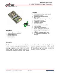
<strong>ZY7120</strong> <strong>20A</strong> <strong>DC</strong>-<strong>DC</strong> <strong>Intelligent</strong> <strong>POL</strong> <strong>Data</strong> <strong>Sheet</strong>3V to 13.2V Input 0.5V to 5.5V Output10. Mechanical DrawingsAll Dimensions are in mmTolerances:0.5-10 0.110-100 0.2Pin Coplanarity: 0.1 max10SMT Pickup Tab13.414±0.30.6 1.27 0.42.54(x10) (x20)3.41.270.25(x10) 1.5 4.32.50.62.0327.949.7532±0.31210.25Tilt Specification:
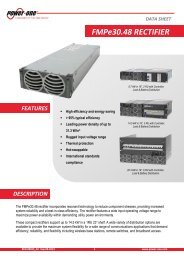
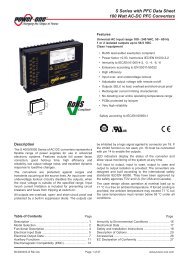
<strong>ZY7120</strong> <strong>20A</strong> <strong>DC</strong>-<strong>DC</strong> <strong>Intelligent</strong> <strong>POL</strong> <strong>Data</strong> <strong>Sheet</strong>3V to 13.2V Input 0.5V to 5.5V Output8.641.23210 10 6(x 3)Unexposed thermal copperarea associated with each padmust be free from other traces1.86 92(x 22)Pin 10.81.27(x 10)2.54 1.27 2.03(x 10)Figure 60. Recommended Pad SizesFigure 61. Recommended PCB Layout for Multilayer PCBsNotes:1. NUCLEAR AND MEDICAL APPLICATIONS - <strong>Power</strong>-<strong>One</strong> products are not designed, intended for use in, or authorized for use as criticalcomponents in life support systems, equipment used in hazardous environments, or nuclear control systems without the express writtenconsent of the respective divisional president of <strong>Power</strong>-<strong>One</strong>, Inc.2. TECHNICAL REVISIONS - The appearance of products, including safety agency certifications pictured on labels, may change depending onthe date manufactured. Specifications are subject to change without notice.I 2 C is a trademark of Philips Corporation.ZD-00194 Rev. 2.5, 01-Jul-10 www.power-one.com Page 34 of 34