Fuel Indexes: A Novel Method for the Evaluation of Relevant ...
Fuel Indexes: A Novel Method for the Evaluation of Relevant ...
Fuel Indexes: A Novel Method for the Evaluation of Relevant ...

You also want an ePaper? Increase the reach of your titles
YUMPU automatically turns print PDFs into web optimized ePapers that Google loves.
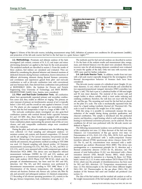
Energy & <strong>Fuel</strong>sArticleFigure 1. Scheme <strong>of</strong> <strong>the</strong> lab-scale reactor, including measurement setup (left), definition <strong>of</strong> common test conditions <strong>for</strong> all experiments (middle),and projection <strong>of</strong> <strong>the</strong> lab-scale reactor fuel bed to <strong>the</strong> fuel layer in a grate furnace (right). 10,112.2. <strong>Method</strong>ology. Proximate and ultimate analyses <strong>of</strong> <strong>the</strong> fuelsinvestigated (ash content, contents <strong>of</strong> N, S, Cl, and major and minorash-<strong>for</strong>ming elements) are applied as <strong>the</strong> basis <strong>for</strong> <strong>the</strong> work presented.The analytical methods are described in section 3. From <strong>the</strong> results <strong>of</strong><strong>the</strong>se analyses, fuel indexes are calculated and evaluated. They aredefined by considering <strong>the</strong> physical behavior and chemical reactions <strong>of</strong>dedicated elements during biomass combustion, known interactions <strong>of</strong>different ash-<strong>for</strong>ming elements during <strong>the</strong>rmal biomass conversion,and correlations and experiences gained from pilot- and real-scalecombustion as well as lab-scale combustion tests with conventionaland new biomass fuels. Data derived from combustion tests per<strong>for</strong>medat BIOENERGY 2020+, <strong>the</strong> Institute <strong>for</strong> Process and ParticleEngineering, Graz University <strong>of</strong> Technology, and BIOS BIOEN-ERGIESYSTEME GmbH, Graz, Austria, were considered.2.3. Pilot- and Real-Scale Combustion Tests. All combustionplants have geometrically separated primary and secondary combustionzones and, thus, enable an efficient air staging. The primary airratio (amount <strong>of</strong> primary air/stoichiometric amount <strong>of</strong> air) is typicallybelow 1 (0.6−0.9), and <strong>the</strong> overall air ratio applied is between 1.4 and1.6. The plants are also equipped with flue gas recirculation, whichensures that <strong>the</strong> bed temperature is kept in a range <strong>of</strong> 900−1100 °C.The real-scale combustion plants investigated are also grate-firedcombustion systems with nominal <strong>the</strong>rmal boiler capacities between0.5 and 110 MW. Also, <strong>the</strong>se boilers are equipped with air-stagingtechnology, and most <strong>of</strong> <strong>the</strong>m are equipped with flue gas recirculation.Grate combustion plants representing <strong>the</strong> present state-<strong>of</strong>-<strong>the</strong>-art werechosen, and only comparable combustion setups were consideredwithin <strong>the</strong> evaluation.During <strong>the</strong> pilot- and real-scale combustion tests, <strong>the</strong> following datawere collected: (1) <strong>Fuel</strong> sampling and subsequent analyses: (i)moisture content, ash content, and chemical composition. (2) Aerosoland fly ash sampling: (i) For aerosol emissions, low-pressure-cascadeimpactors (Berner-type low-pressure impactors) were used. (ii) Fortotal fly ash emissions, <strong>the</strong> gravimetric method according to VDI 2066was used. (3) Deposit sampling with deposit probes. (4) Emissionmeasurements concerning CO, CO 2 , NO, NO x ,O 2 ,SO x , and HCl: (i)CO, CO 2 , and O 2 were measured with a multi-component gas analyzer(Rosemount NGA 2000). This device uses non-dispersive infraredmeasurement technique (NDIR) <strong>for</strong> CO and CO 2 analyses andparamagnetism as a measurement principle <strong>for</strong> O 2 detection. (ii) Anitric oxide analyzer (ECO Physis CLD 700 El ht), which uses <strong>the</strong>principle <strong>of</strong> chemiluminescence, has been used <strong>for</strong> NO and NO xdetection. (iii) The SO x and HCl emissions were per<strong>for</strong>med bydiscontinuous measurements according to VDI 3480, Sheet 1. (5)Determination <strong>of</strong> <strong>the</strong> furnace temperatures. (6) Sampling <strong>of</strong> allrelevant ash fractions (bottom ash, furnace ash, cyclone ash, filter flyash, and aerosols) and subsequent analyses: (i) chemical composition.(7) Recording <strong>of</strong> all relevant operating parameters (O 2 content in <strong>the</strong>flue gas, furnace temperature, load, combustion air supply, etc.)The methods used <strong>for</strong> fuel and ash analyses are described in section3. On <strong>the</strong> basis <strong>of</strong> <strong>the</strong> analysis results and measurement data, energy,mass, and element balances over <strong>the</strong> plant were calculated. Moreover,recovery rates <strong>for</strong> all ash-<strong>for</strong>ming elements considered were evaluatedto ensure <strong>the</strong> quality <strong>of</strong> <strong>the</strong> data. Only test runs with recovery rates>90% were used <strong>for</strong> fur<strong>the</strong>r evaluation.2.4. Lab-Scale Reactor Tests. In addition, results from test runswith a lab-scale reactor especially designed <strong>for</strong> <strong>the</strong> investigation <strong>of</strong> <strong>the</strong><strong>the</strong>rmal decomposition behavior <strong>of</strong> biomass fuels have beenconsidered.This lab-scale reactor consists <strong>of</strong> a cylindrical retort (height, 35 cm;inner diameter, 12 cm), which is heated electrically and controlled bytwo separated proportional−integral−derivative (PID) controllers (seeFigure 1, left). The fuel is put in a cylindrical holder <strong>of</strong> 100 mm heightand 95 mm inner diameter. The material <strong>of</strong> <strong>the</strong> reactor wall andsample holder is silicon carbide, which is inert under reducing andoxidizing conditions; <strong>the</strong>re<strong>for</strong>e, <strong>the</strong> wall does not react with <strong>the</strong> fuel,ash, and flue gas. The mounting and vessel <strong>for</strong> <strong>the</strong> fuel bed are placedon <strong>the</strong> plate <strong>of</strong> a scale. The scale is mechanically separated from <strong>the</strong>retort by a liquid sealing (syn<strong>the</strong>tic <strong>the</strong>rmal oil: Therminol 66). Thescale is used to determine <strong>the</strong> weight loss <strong>of</strong> <strong>the</strong> sample.With this setup, it is possible to continuously measure <strong>the</strong> massreduction <strong>of</strong> <strong>the</strong> sample during drying, pyrolysis, gasification, andcharcoal combustion. The sample is introduced into <strong>the</strong> preheatedreactor, and <strong>the</strong>re<strong>for</strong>e, a rapid heating, which is well-comparable to <strong>the</strong>heating in real <strong>the</strong>rmal conversion processes, can be achieved. The testconditions <strong>for</strong> all test runs per<strong>for</strong>med with <strong>the</strong> lab-scale reactor aredefined in Figure 1.The following measurements/analyses were per<strong>for</strong>med during each<strong>of</strong> <strong>the</strong> combustion test runs: (1) Mass decrease <strong>of</strong> <strong>the</strong> fuel over time(balance). (2) Concentrations <strong>of</strong> flue gas species over time: (i)Determination <strong>of</strong> CO 2 ,H 2 O, CO, CH 4 ,NH 3 , HCN, N 2 O, and basichydrocarbons was per<strong>for</strong>med with a multi-component Fouriertrans<strong>for</strong>m infrared (FTIR) spectroscopy device (Ansyco Series 447).(ii) The O 2 and H 2 concentrations were measured with a multicomponentgas analyzer (Rosemount NGA 2000). This device usesparamagnetism as a measurement principle <strong>for</strong> O 2 detection and a<strong>the</strong>rmal conductivity detector (TCD) <strong>for</strong> H 2 detection. (iii) Theamount <strong>of</strong> total hydrocarbons (C x H y ) was determined with a flameionization detector (FID, Bernath Atomic 3005), which detectsorganic compounds by ionization in a burning H 2 flame. (iv) Widebandλ sensor (O 2 ). (v) A nitric oxide analyzer (ECO Physis CLD 700El ht), which uses <strong>the</strong> principle <strong>of</strong> chemiluminescence, has been used<strong>for</strong> NO and NO 2 detection. (3) Temperature measurements overtime: (i) Five <strong>the</strong>rmocouples in <strong>the</strong> fuel bed (three different heightsNiCr−Ni). (ii) Thermocouples in <strong>the</strong> gas phase (NiCr−Ni). (4)Analysis <strong>of</strong> <strong>the</strong> biomass fuel used and residual ash produced (seesection 3).The data <strong>of</strong> <strong>the</strong> fuel analysis and <strong>the</strong> residual ash analysis as well as<strong>the</strong> weight measurements <strong>of</strong> <strong>the</strong> fuel sample and <strong>the</strong> ash sample can beCdx.doi.org/10.1021/ef201282y | Energy <strong>Fuel</strong>s XXXX, XXX, XXX−XXX