GSM & GPRS Modem - RF Solutions
GSM & GPRS Modem - RF Solutions
GSM & GPRS Modem - RF Solutions

Create successful ePaper yourself
Turn your PDF publications into a flip-book with our unique Google optimized e-Paper software.
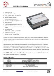
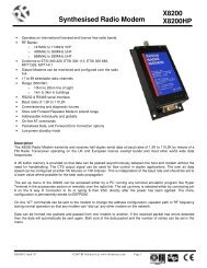
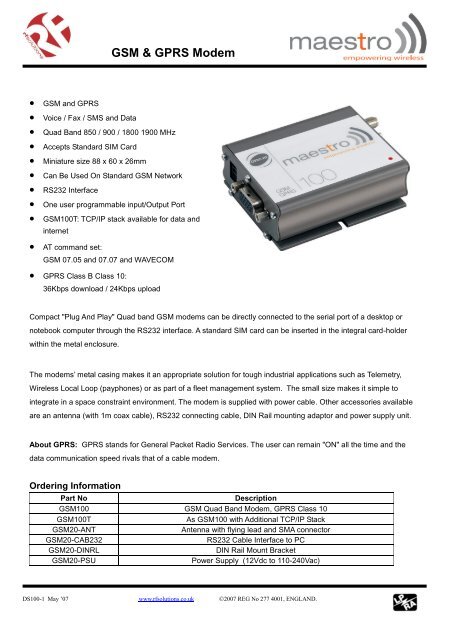
<strong>GSM</strong> & <strong>GPRS</strong> <strong>Modem</strong> <strong>GSM</strong> and <strong>GPRS</strong> Voice / Fax / SMS and Data Quad Band 850 / 900 / 1800 1900 MHz Accepts Standard SIM Card Miniature size 88 x 60 x 26mm Can Be Used On Standard <strong>GSM</strong> Network RS232 Interface One user programmable input/Output Port <strong>GSM</strong>100T: TCP/IP stack available for data andinternet AT command set:<strong>GSM</strong> 07.05 and 07.07 and WAVECOM <strong>GPRS</strong> Class B Class 10:36Kbps download / 24Kbps uploadCompact "Plug And Play" Quad band <strong>GSM</strong> modems can be directly connected to the serial port of a desktop ornotebook computer through the RS232 interface. A standard SIM card can be inserted in the integral card-holderwithin the metal enclosure.The modems’ metal casing makes it an appropriate solution for tough industrial applications such as Telemetry,Wireless Local Loop (payphones) or as part of a fleet management system. The small size makes it simple tointegrate in a space constraint environment. The modem is supplied with power cable. Other accessories availableare an antenna (with 1m coax cable), RS232 connecting cable, DIN Rail mounting adaptor and power supply unit.About <strong>GPRS</strong>: <strong>GPRS</strong> stands for General Packet Radio Services. The user can remain "ON" all the time and thedata communication speed rivals that of a cable modem.Ordering InformationPart NoDescription<strong>GSM</strong>100 <strong>GSM</strong> Quad Band <strong>Modem</strong>, <strong>GPRS</strong> Class 10<strong>GSM</strong>100TAs <strong>GSM</strong>100 with Additional TCP/IP Stack<strong>GSM</strong>20-ANTAntenna with flying lead and SMA connector<strong>GSM</strong>20-CAB232RS232 Cable Interface to PC<strong>GSM</strong>20-DINRLDIN Rail Mount Bracket<strong>GSM</strong>20-PSUPower Supply (12Vdc to 110-240Vac)DS100-1 May ’07 www.rfsolutions.co.uk 2007 REG No 277 4001, ENGLAND.
1<strong>GSM</strong> & <strong>GPRS</strong> <strong>Modem</strong>CONTENTSSAFETY PRECUTIONS 2CHAPTER 1 INTRODUCTION 3CHAPTER 2 INSTALLATION 7CHAPTER 3 WORKING WITH MAESTRO 100 9CHAPTER 4 SPECIFICATION 12CHAPTER 5 APPENDIX 13CHAPTER 6 TROUBLESHOOTING 14DS100-1 May ’07 www.rfsolutions.co.uk 2007 REG No 277 4001, ENGLAND. Page 1
2<strong>GSM</strong> & <strong>GPRS</strong> <strong>Modem</strong>SAFETY PRECUTIONS• The modem generates radio frequency (<strong>RF</strong>) power. When using the modem care must be taken onsafety issues related to <strong>RF</strong> interference as well as regulations of <strong>RF</strong> equipment.• Do not use your phone in aircraft, hospitals, petrol stations or in places where using <strong>GSM</strong> products isprohibited.• Be sure that the modem will not be interfering with nearby equipment. For example: pacemakers ormedical equipment. The antenna of the modem should be away from computers, office equipment,home appliance, etc.• An external antenna must be connected to the modem for proper operation. Only uses approvedantenna with the modem. Please contact authorized dealer on finding an approved antenna.• Always keep the antenna with minimum safety distance of 26.6 cm or more from human body. Do notput the antenna inside metallic box, containers, etc.Using the modem in vehicle• Check for any regulation or law authorizing the use of <strong>GSM</strong> in vehicle in your country before installingthe modem• Install the modem by qualified personnel. Consult your vehicle dealer for any possible interference ofelectronic parts by the modem.• The modem should be connected to the vehicle’s supply system by using a fuse-protected terminal inthe vehicle’s fuse box• Be careful when the modem is powered by the vehicle’s main battery. The battery may be drained afterextended period.Protecting your modem• To ensure error-free usage, please install and operate your modem with care. Do remember thefollowing:• Do not expose the modem to extreme conditions such as high humidity/rain, high temperatures, directsunlight, caustic/harsh chemicals, dust, or water.• Do not try to disassemble or modify the modem. There is no user serviceable part inside and thewarranty would be void.• Do not drop, hit or shake the modem. Do not use the modem under extreme vibrating condition.• Do not pull the antenna or power supply cable. Attach/ detach by holding the connector.• Connect the modem only according to the instruction manual. Failure to do it will void the warranty.• In case of problem, please contact authorized dealer.GENERALDS100-1 May ’07 www.rfsolutions.co.uk 2007 REG No 277 4001, ENGLAND. Page 2
3<strong>GSM</strong> & <strong>GPRS</strong> <strong>Modem</strong>CHAPTER 1INTRODUCTIONMaestro 100 is a ready-to-use <strong>GSM</strong> modem for voice, data, fax and SMS services. It also supports <strong>GPRS</strong>Class 10 for hi-speed data transfer. Maestro 100 can be easily controlled by using AT command for allkinds of operations. With standard 9-pin RS232 port the Maestro 100 can be set up with minimal effort.1.1. PackageThe Maestro 100 package should include the following:1. Maestro 100 or 100T x 12. Power cord with fuse x 13. Safety note x 11.2. InterfacesSIM holder eject buttonSMA female antenna connectorStatus indicator15 pin Sub-D Female Connector(RS232/Audio)SIM holder4-PIN connector (Power, Input / Output)1.2.1. Status indicatorThe LED will indicate different status of the modem:- off <strong>Modem</strong> switched off- on <strong>Modem</strong> is connecting to the network- flashing slowly <strong>Modem</strong> is in idle mode- flashing rapidly <strong>Modem</strong> is in transmission/communication (<strong>GSM</strong> only)1.2.2. SMA female antenna connector- Connect this to an external antenna with SMA male connector. Make sure the antenna is for thecorrect <strong>GSM</strong> frequency with impedance of 50ohm, and also connector is secured tightly.DS100-1 May ’07 www.rfsolutions.co.uk 2007 REG No 277 4001, ENGLAND. Page 3
4<strong>GSM</strong> & <strong>GPRS</strong> <strong>Modem</strong>1.2.3. 15-PIN D-SUB Female connector (RS232 / Audio)- The connector provides serial link and audio link to the modem.Pin number Name EIA designation Type Note1 DCD Data Carrier Detect Output2 TX Transmit Data Input3 BOOT Input Not used4 MICROPHONE (+) Input With 2V DC bias5 MICROPHONE (-) Inputoutput6 RX Receive Data Output7 DSR Data Set Ready Output8 DTR Data Terminal Ready Input9 GND Ground Ground10 SPEAKER(+) Output11 CTS Clear to Send Output12 RTS Request to Send Input13 RI Ring Indicator Output14 RESET Input Pull low to reset15 SPEAKER(-) OutputSpecification of microphone and speaker to be connected :Parameters Min Typical Max RemarkMicrophone current @2V / 2K Ohm0.5 mAMicrophone input level100 mVppSpeaker output current 150 Ohm/ 1nF16mASpeaker impedance 32ohm 50ohmPlease refer to the document “Application notes - Power supply & Audio” for more information of audioconnection.1.2.4. 4-PIN connector (Power, Input / Output)Pin assignment of 4-pin connectorPin number Name Functions1 I/O Input / Output port2 ~INTR Interrupt function triggered by pulling this pin toground or LOW level; reserved for additionalfunctions with new firmware3 POWER - DC power negative input4 POWER+ DC power positive inputDS100-1 May ’07 www.rfsolutions.co.uk 2007 REG No 277 4001, ENGLAND. Page 4
5<strong>GSM</strong> & <strong>GPRS</strong> <strong>Modem</strong>A cable, included in the package shall be used for power supply connection:5-32V DCSupplyConnector Micro-Fit 3.0(to Fargo Maestro)Fuse holderFuse rating :Stripped wireI/O250V 2.5AParameters Min Typical Max RemarkI/O In LOW voltage 0.5VI/O In HIGH voltage 3V 5VI/O out max. sink current 5mA Internal 1k resistor in seriesINTRParameters Min Typical Max RemarkInput LOW voltage 0 0.5V Triggered by pulling this pin toLOW level ; otherwise leave itopenPlease refers to Chapter 6 Appendix for using I/O and INTR signals. Contact your dealer if you needwire for the I/O and INTR connection1.2.5 Optional accessoriesYou may contact your sales agent for the following optional accessories:External antenna- Magnetic mount type- Frequency <strong>GSM</strong> 900/1800 band- Gain 3db- VSWR < 1.5:1- Height ~ 236 mm (including magnetic base)- Cable : Type RG-174U length 2.5m- SMA male connector on cable end- color : back (SMA connector silver)DS100-1 May ’07 www.rfsolutions.co.uk 2007 REG No 277 4001, ENGLAND. Page 5
8<strong>GSM</strong> & <strong>GPRS</strong> <strong>Modem</strong>2.4 Connect the modem to external deviceYou can use the optional ‘Y’ cable to connect the modem’s Sub-D connector to externalcontroller/computer. Note : The modem CANNOT be connected to the ‘Line’ jack of a landline telephonedirectly.Connection example using optional ‘Y’ cable:2.5 Connecting the DC power supplyConnect the open ending of the included power cord to a DC supply. Refer to the following for powersupply requirement.Input voltage rangeRated current5V – 32V650 mAAC-DC Adaptoror battery(not included)Solder wireendingsConnect the connector to the modem. The modem will turn on automatically.The status indicator on the modem will be lit when power on. After a few seconds it will go flashing slowly(registered to the network successfully, refer section 1.2.1).Chapter 3 describes how to communicate with the modem in Microsoft Windows TM environment.DS100-1 May ’07 www.rfsolutions.co.uk 2007 REG No 277 4001, ENGLAND. Page 8
9<strong>GSM</strong> & <strong>GPRS</strong> <strong>Modem</strong>CHAPTER 3WORKING WITH MAESTRO 1003.1. Checking the modem (using Microsoft Windows XP HyperTerminal asexample)3.1.1. On the first time power-up you can use a terminal software to communicate with the modemthrough an RS-232 serial port. Following example is using the HyperTerminal in Windows XP .3.1.2. On Windows XP, start the HyperTerminal program. Assign a name for a new session.DS100-1 May ’07 www.rfsolutions.co.uk 2007 REG No 277 4001, ENGLAND. Page 9
<strong>GSM</strong> & <strong>GPRS</strong> <strong>Modem</strong>103.1.3. Choose the correct Com port and baud rate settings (9600bps for Eco; 115200bps for others,8bits, no parity bit, 1 stop bit).3.1.4. On the terminal screen, type “AT” to check the “OK” response from the modemDS100-1 May ’07 www.rfsolutions.co.uk 2007 REG No 277 4001, ENGLAND. Page 10
11<strong>GSM</strong> & <strong>GPRS</strong> <strong>Modem</strong>3.2. Basic Operation :Followings are examples of some AT commands. Please refer to the AT Command guide for a fulldescription.Note: Issue AT+CMEE=1 to have extended error code (+CME ERROR)Description AT commands <strong>Modem</strong> response CommentsNetwork RegistrationCheckingAT+CREG? CREG=,1 <strong>Modem</strong> registered to the networkCREG=,2Registration lost, re-registration attemptCREG=,0<strong>Modem</strong> not registration on the network, noregistration attemptReceiving signalstrengthReceiving anincoming callAT+CSQ +CSQ: 20,0 The first parameter has to be at least 15 for normalcommunicationRINGAn incoming call is waitingATAAnswer the callOKMake a call ATD1234567; Don’t forget the « ; » at the end for « voice » callOKCommunication establishedCME ERROR : 11PIN code not entered (with + CMEE = 1 mode)CME ERROR : 3AOC credit exceeded or a communication is alreadyestablishedCME ERROR : 10Cannot read the SIM cardMake an emergencycallATD 112;OKDon’t forget the « ; » at the end for « voice » callCommunication lossNO CARRIERHang upATHOKEnter PIN codeAT+CPIN=1234OKPIN Code accepted+CME ERROR : 16Incorrect PIN Code (with +CMEE = 1 mode)+CME ERROR : 3PIN already entered (with +CMEE = 1 mode)Automatically answercallsATS0? 002OKATS0=2 OK Sets the modem to answer after 2 ringsATS0=0 OK Resets the modem to no automatic answerSaves parameters innon-volatile memoryAT&WOKThe configuration settings are storedDS100-1 May ’07 www.rfsolutions.co.uk 2007 REG No 277 4001, ENGLAND. Page 11
12<strong>GSM</strong> & <strong>GPRS</strong> <strong>Modem</strong>CHAPTER 4SPECIFICATION• Bands 850 / 900 / 1800 / 1900 Mhz• Support Data, SMS, Voice and Fax• Max Power Output: 2W(900Mhz), 1W(1800Mhz)• Group 3 FAX support (Class 1 and 2)• <strong>GPRS</strong> Class B Class 10 (4Rx+1Tx or 3Rx+2Tx) at maximum speed.*• SimToolKit Class 2• AT command set (<strong>GSM</strong> 07.05, <strong>GSM</strong> 07.07 and WAVECOM proprietary)* Note : Available slot for <strong>GPRS</strong> connection is network dependent.Power requirementInput voltage rangeRated current5V – 32V650 mATypical current consumption@5V @12V @32V<strong>GSM</strong>850 communication mode PCL5 310mA 130mA 50mAE<strong>GSM</strong>900 communication mode PCL5 310mA 130mA 50mADCS1800 communication mode PCL0 240mA 100mA 40mAPCS1900 communication mode PCL0 240mA 100mA 40mA<strong>GPRS</strong>850 Class 10 520mA 220mA 80mA<strong>GPRS</strong>900 Class 10 520mA 220mA 80mA<strong>GPRS</strong>1800 Class 10 390mA 160mA 70mA<strong>GPRS</strong>1900 Class 10 390mA 160mA 70mAIdle mode 35mA 16mA 8mAIdle mode with power saving on RS232 12mA 11mA 5mADimensions:• Overall size : 88mm x 60mm x 26mm• Weight : 100g• Temperature range: operating -30 o C to +75 o C (Ext model) -20 o C to +55 o C (other models)storage -40 o C to +85 o C (Ext model) -25 o C to +70 o C (other models)DS100-1 May ’07 www.rfsolutions.co.uk 2007 REG No 277 4001, ENGLAND. Page 12
13<strong>GSM</strong> & <strong>GPRS</strong> <strong>Modem</strong>CHAPTER 5APPENDIX5.1 Factory settingsThe modem has the following factory settings. Please refer to the AT command document for the meaningof each setting.Related AT commands Factory Settings DescriptionAT+IPR 115200 (9600 for Eco) DTE-DCE data rateAT+IFC 2,2 DTE-DCE flow controlAT+ICF 3,4 DTE-DCE character framingATE 1 ECHOAT&C 1 DCD signalAT&D 2 DTR signalATQ 0 Result code suppressionATV 1 Response formatAT&S 1 DSR signalATS0 0 Auto answerAT+CLIP 0 Calling line ID presentationAT+CRLP 0 Calling line ID restrictionAT+CSCS “PCCP437” Character setAT+CMGF 1 Short Message formatAT+CSMP 1,67,0,0 Text mode parameters *AT+CNMI 0,1,0,0 New message indication **Note: settings stored in SIM, not in modem5.2 Input / Output portThis port can be configured as either an input one or an output one.To configure it as an input port, first issue AT+WIOW=2, 0 to disable the output port. Use AT+WIOR=3 toread the status of this input port. Response +WIOR: 0 represent Logic HIGH (>3V); Response +WIOR: 1represent Logic LOW (
14<strong>GSM</strong> & <strong>GPRS</strong> <strong>Modem</strong>CHAPTER 66.1 The modem’s LED does not light :Check if the modem has connected to a 5-32V power supply properlyCheck if the power connector is properly insertedCheck the fuse on the power cordTROUBLESHOOTING6.2 The modem’s LED lights but does not blink long time after power upCheck if a valid SIM card has been inserted properlyCheck if the SIM card has been locked (refer to AT+CPIN command in AT command guide)Check if the external has been connected properly to the modemCheck if the network coverage is available.6.3 The modem does not response to the terminal programCheck if the RS-232 cable has been connected properlyCheck if your program has proper setting. Factory setting of the modem is:115200bps (9600bps for Maestro 100 Eco)8 data bitsno parity bit1 stop bit6.4 No voice could be heard for the modem’s speaker output when a call isansweredMake sure a voice call has been made (refer to AT command guide)Enter the AT+SPEAKER=1 commandFor more information or general enquiries:R F <strong>Solutions</strong> Ltd.Unit 21, Cliffe Industrial Estate,South Street, Lewes, BN8 6JL, England.Email: sales@rfsolutions.co.uk Web: http://www.rfsolutions.co.ukTel: +44 (0)1273 898 000 Fax: +44 (0)1273 480 661DS100-1 May ’07 www.rfsolutions.co.uk 2007 REG No 277 4001, ENGLAND. Page 14