Synthesised Radio Modem X8200 X8200HP - RF Solutions
Synthesised Radio Modem X8200 X8200HP - RF Solutions
Synthesised Radio Modem X8200 X8200HP - RF Solutions

Create successful ePaper yourself
Turn your PDF publications into a flip-book with our unique Google optimized e-Paper software.
<strong>Synthesised</strong> <strong>Radio</strong> <strong>Modem</strong><br />
<strong>X8200</strong><br />
<strong>X8200</strong>HP<br />
• Operates on international licensed and licence free radio bands<br />
• <strong>RF</strong> Bands:<br />
o 147MHz to 174MHz VHF<br />
o 400MHz to 500MHz UHF<br />
o 868MHz to 920MHz UHF<br />
• Conforms to ETSI 300-220, ETSI 300-113, ETSI 300-683,<br />
MPT1329, MPT1411<br />
• Distant <strong>Modem</strong>s can be monitored and configured over the radio<br />
link<br />
• 17 to 99 selectable radio channels<br />
• Range (500mW):<br />
o 10km to 20km line of sight<br />
o 1km to 3km in buildings<br />
• RS232 & RS485 serial Interface<br />
• Baud rates of 1.2K to 115.2K<br />
• Commissioning and diagnostic futures<br />
• Store and Forward Repeater Mode to extend range<br />
• Addressable individually and globally<br />
• On-line AT commands<br />
• Packetised Data, and Forward Error Correction options<br />
• Low power standby mode<br />
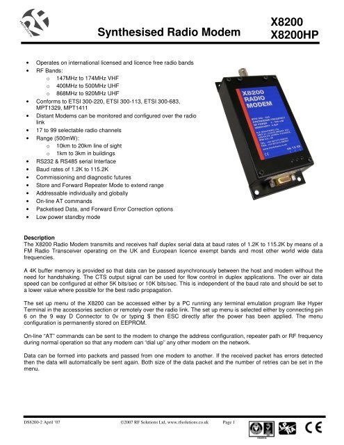
Description<br />
The <strong>X8200</strong> <strong>Radio</strong> <strong>Modem</strong> transmits and receives half duplex serial data at baud rates of 1.2K to 115.2K by means of a<br />
FM <strong>Radio</strong> Transceiver operating on the UK and European licence exempt bands and most other world wide data<br />
frequencies.<br />
A 4K buffer memory is provided so that data can be passed asynchronously between the host and modem without the<br />
need for handshaking. The CTS output signal can be used for flow control in duplex applications. The over air data<br />
speed can be configured at either 5K bits/sec or 10K bits/sec. This is independent of the baud rate and should be set to<br />
a lower value where possible for the best radio propagation.<br />
The set up menu of the <strong>X8200</strong> can be accessed either by a PC running any terminal emulation program like Hyper<br />
Terminal in the accessories section or remotely over the radio link. The set up menu is selected either by connecting pin<br />
6 on the 9 way D Connector to 0v or typing $ then ESC directly after the power has been applied. The menu<br />
configuration is permanently stored on EEPROM.<br />
On-line “AT” commands can be sent to the modem to change the address configuration, repeater path or <strong>RF</strong> frequency<br />
during normal operation so that any modem can “dial up” any other modem on the network.<br />
Data can be formed into packets and passed from one modem to another. If the received packet has errors detected<br />
then the data will automatically be sent again. Both size of the data packet and the number of retries can be set in the<br />
menu.<br />
DS8200-2 April ’07 ©2007 <strong>RF</strong> <strong>Solutions</strong> Ltd, www.rfsolutions.co.uk Page 1
<strong>Synthesised</strong> <strong>Radio</strong> <strong>Modem</strong><br />
<strong>X8200</strong><br />
<strong>X8200</strong>HP<br />
INDEX<br />
1 Specification .................................................................................................3<br />
1.1 Mechanical and Environmental ..............................................................3<br />
2 Connections ..................................................................................................4<br />
2.1 9 Way D Type Connector RS232/RS485...............................................4<br />
2.2 LED Indicators........................................................................................5<br />
2.3 Antenna Connector .................................................................................5<br />
3 Operation ......................................................................................................5<br />
4 Getting started...............................................................................................5<br />
4.1 Basic Connection ....................................................................................5<br />
4.2 Power Connection...................................................................................5<br />
4.3 Factory Setting........................................................................................6<br />
4.4 Plug and Play ..........................................................................................6<br />
5 Configuration................................................................................................7<br />
5.1 Access Configuration Menu ...................................................................7<br />
5.2 Configuration Menu................................................................................8<br />
6 <strong>Radio</strong> Transmission....................................................................................16<br />
7 Trouble shooting.........................................................................................18<br />
DS8200-2 April ’07 ©2007 <strong>RF</strong> <strong>Solutions</strong> Ltd, www.rfsolutions.co.uk Page 2
<strong>Synthesised</strong> <strong>Radio</strong> <strong>Modem</strong><br />
<strong>X8200</strong><br />
<strong>X8200</strong>HP<br />
1 Specification<br />
ELECTRICAL CHARACTERISTICS MIN TYPICAL MAX DIMENSION NOTE<br />
Frequency Range 868 920 MHz<br />
458.500 458.950 MHz UK<br />
400.000 480.000 MHz World<br />
147.000 174.000 MHz<br />
Si (<strong>X8200</strong> HP<br />
Only)<br />
Channels 127<br />
Channel Separation 12.5 25.0 25.0 KHz<br />
Start up Time 5.0 10.0 30.0 mSecs With $ Selected<br />
Modulation<br />
F3D, F1D<br />
Power Supply <strong>X8200</strong><br />
10 12 26 Vdc<br />
<strong>X8200</strong>HP 10 12 14 Vdc<br />
Baud Rate 1.2 115.2 Kb/s<br />
TRANSMITTER<br />
<strong>RF</strong> Power <strong>X8200</strong> 5 500 mW<br />
<strong>RF</strong> Power <strong>X8200</strong>HP 1 5 W<br />
Data Input RS232 -10 10 V<br />
Data Input RS485 0 5 V<br />
Frequency Deviation +/- 3.0 KHz 25KHz Channel<br />
Modulation Rate DC 10.0 Kbps<br />
Supply Current <strong>X8200</strong><br />
<strong>X8200</strong>HP<br />
340<br />
1800<br />
RECEIVER<br />
IF Frequencies 45/455 MHz<br />
Sensitivity 0.9 V<br />
Bandwidth +/- 7.5 KHz<br />
Data Output RS232 -10 10 V<br />
Data Output RS485 0 5 V<br />
Carrier Detect -10 10 V<br />
Supply Current <strong>X8200</strong><br />
90<br />
<strong>X8200</strong>HP<br />
150<br />
mA<br />
Supply Current Standby 0.005 0.007 0.01 mA<br />
mA<br />
1.1 Mechanical and Environmental<br />
Dimensions <strong>X8200</strong> UHF 800mW<br />
Dimensions <strong>X8200</strong>HP UHF 5W<br />
Dimensions <strong>X8200</strong>HP VHF 5W<br />
Operating Temperature Range<br />
Length = 140mm Width = 65mm Height = 26mm<br />
Length = 147mm Width = 65mm Height = 52mm<br />
Length = 174mm Width = 80mm Height = 58mm<br />
-10 to +55 deg C<br />
DS8200-2 April ’07 ©2007 <strong>RF</strong> <strong>Solutions</strong> Ltd, www.rfsolutions.co.uk Page 3
<strong>Synthesised</strong> <strong>Radio</strong> <strong>Modem</strong><br />
<strong>X8200</strong><br />
<strong>X8200</strong>HP<br />
2 Connections<br />
2.1 9 Way D Type Connector RS232/RS485<br />
1 +VE POWER INPUT<br />
6 CONFIGURATION MODE INPUT<br />
2 RS232 RD RECEIVE DATA INPUT<br />
7 -VE RS485 INPUT/OUTPUT<br />
3 RS232 TD TRANSMIT DATA OUTPUT<br />
8 CTS OUTPUT<br />
4 DTR (STANDBY) INPUT<br />
9 +VE RS485 INPUT/OUTPUT<br />
5 0V INPUT<br />
Pin Connection Description<br />
1 +VE Regulated power supply. It is not advisable to use some types of switched mode power<br />
supply either to drive the <strong>X8200</strong> radio modem or in close proximity to it. This type of power<br />
supply can produce high energy radio frequencies over a broad spectrum thereby causing<br />
interference to the received signal.<br />
2 RD RS232 Receive serial data from host<br />
3 TD RS232 Transmit serial data to host<br />
4 DTR A signal of between 0v to –7V will switch the modem into standby power mode. Leave<br />
open circuit for normal use<br />
5 GND Power supply and common for host.<br />
6 CON Configuration input. Connecting 0V to this input will send the configuration menu to the<br />
host when the power is applied. It is left open circuit for normal operation<br />
7 –VE RS485 Bi-directional data.<br />
8 CTS Brought low by the modem when a <strong>RF</strong> carrier is detected or the receiver buffer memory is<br />
full. This can be connected to RTS on the host to inhibit data from the host in duplex<br />
operations.<br />
9 +VE RS485 Bi-directional data.<br />
DS8200-2 April ’07 ©2007 <strong>RF</strong> <strong>Solutions</strong> Ltd, www.rfsolutions.co.uk Page 4
<strong>Synthesised</strong> <strong>Radio</strong> <strong>Modem</strong><br />
<strong>X8200</strong><br />
<strong>X8200</strong>HP<br />
2.2 LED Indicators<br />
Three LEDS on the front of the modem indicate the following states:<br />
TX Green On when modem is transmitting data.<br />
RX Green On when a <strong>RF</strong> carrier of greater than 0.9uV is detected by the modem.<br />
POWER Red On when power is applied to the modem<br />
2.3 Antenna Connector<br />
BNC/TNC<br />
3 Operation<br />
A transmission is started by sending data to RD (pin 2) or the RS485 terminals (pin7 & 9).The radio modem places<br />
this data in the transmitter buffer memory while it checks to see if the <strong>RF</strong> channel is free. If it is not then the data is<br />
stored in the buffer until the channel becomes free. If it is free then a preamble message will be transmitted so that<br />
the receiving modems can align to the incoming data. When Tx Priority is set, data will be transmitted regardless of<br />
the condition of the <strong>RF</strong> Channel.<br />
The modem will then transmit a command byte which will instruct the distant modems to perform the functions set in<br />
the menu followed by the addressing and repeater functions. The data that has been placed in the buffer memory will<br />
then be transmitted. The transmission is terminated when a gap of two data bytes is detected in the incoming data<br />
stream.<br />
If more data is sent after a gap of two data bytes then the above sequence will be repeated.<br />
When the receiving modem detects the presence of incoming data it takes CTS (pin 8) low. The repeater command<br />
byte is decoded and the transmitter address compared to the receiver address. If they are the same or if the global<br />
address of 00 is decoded or if the address mode is switched off then the data will be presented at the serial output<br />
port TD (pin 3). At the end of the message CTS is taken high.<br />
If the packetisation option is selected the receiving modem will check the CRC byte. If it is correct an ACK sent to the<br />
transmitting modem. If the CRC is incorrect a NACK is sent to the transmitting modem and the data is sent again.<br />
The number of re-trys are set in the Menu.<br />
If the repeater command is decoded or the repeater mode set in the configuration menu then the data will be stored<br />
and then re-transmitted.<br />
4 Getting started<br />
4.1 Basic Connection<br />
TRANSMIT (TD) ON HOST TO RECEIVE (RD) ON MODEM PIN 2<br />
RECEIVE (RD) ON HOST TO TRANSMIT (TD) ON MODEM PIN 3<br />
GROUND (0V) ON HOST TO 0V ON MODEM PIN 5<br />
4.2 Power Connection<br />
PIN 1 = POSITIVE<br />
PIN 5 = GND<br />
DS8200-2 April ’07 ©2007 <strong>RF</strong> <strong>Solutions</strong> Ltd, www.rfsolutions.co.uk Page 5
<strong>Synthesised</strong> <strong>Radio</strong> <strong>Modem</strong><br />
<strong>X8200</strong><br />
<strong>X8200</strong>HP<br />
4.3 Factory Setting<br />
The radio modem is supplied with the following settings:<br />
<strong>X8200</strong> <strong>Radio</strong> <strong>Modem</strong> V#.#<br />
Advanced Menu Y<br />
<strong>Modem</strong> ID 01<br />
Baud 9600<br />
Parity<br />
N<br />
Odd/Even E<br />
<strong>RF</strong> Power 5<br />
Key Transmitter N<br />
<strong>RF</strong> Channel 17<br />
RSSI<br />
N<br />
Sensitivity 00<br />
Comms Speed S<br />
Address Mode N<br />
Enable AT Instr N<br />
Restore Defaults N<br />
Exit without Save N<br />
Save & Exit N<br />
Advanced Menu<br />
Return to Main Menu Y<br />
Message Tag 0000<br />
TX Priority<br />
N<br />
FEC<br />
N<br />
Packetise Data N<br />
Number of Retries 05<br />
Packet Size 20<br />
Logger Mode<br />
N<br />
Enable Remote Access Y<br />
Access Remote <strong>Modem</strong> N<br />
Engage Repeater Path N<br />
Set Repeater Path 00<br />
M01 M02 M03 M04 M05 M06 ---- M16<br />
4.4 Plug and Play<br />
Connect three wires to the RS232 serial port of the host terminal (0V, TD and RD) as<br />
described above. Connect a regulated power supply to the radio modem. X7202 PC to<br />
<strong>Modem</strong> cables can be used along with a X7201 power supply.<br />
Configure a PC to Hyperterminal in the Accessories section to the following:<br />
Go to File and then t Properties.<br />
Set the Configuration to :<br />
9600 Baud<br />
No Parity<br />
1 Stop Bit<br />
XON/XOFF to OFF<br />
RTS/CTS to OFF (no handshaking)<br />
Settings should be: Terminal Keys set<br />
Emulation set to ANSI<br />
ASCII Set Up : Deselect all.<br />
Connect up a second modem in the same way.<br />
Pressing a key on one PC will transmit the character to the other. Refer to the Section 8.0<br />
Trouble Shooting if this does not happen.<br />
DS8200-2 April ’07 ©2007 <strong>RF</strong> <strong>Solutions</strong> Ltd, www.rfsolutions.co.uk Page 6
<strong>Synthesised</strong> <strong>Radio</strong> <strong>Modem</strong><br />
<strong>X8200</strong><br />
<strong>X8200</strong>HP<br />
If a second PC is not available simply power up the second modem. Configure the ID<br />
numbers and the Enable Remote Access option on both. Then use the Access Remote<br />
<strong>Modem</strong> option to display the menu of the remote modem.<br />
Fig 1 shows how an open network using the above configuration would work. All the data<br />
transmitted from one modem will be received by all of the others. This is similar to an<br />
RS485 network but instead of connecting the equipment by wire a radio modem is used.<br />
5 Configuration<br />
5.1 Access Configuration Menu<br />
FIGURE 1 OPEN NETWORK<br />
There are three ways the menu can be accessed:<br />
Typing $ then pressing the Esc Key as the first two characters after the <strong>Radio</strong> <strong>Modem</strong>s has<br />
been switched on.<br />
Connecting Pin 6 on the D-connector to 0V on Pin 5. Then switching the <strong>Radio</strong> <strong>Modem</strong> on.<br />
Using the Remote Access feature to display the menu of a distant <strong>Radio</strong> <strong>Modem</strong>.<br />
A PC configured as a dumb terminal with the following settings should be used:<br />
9600 Baud<br />
No Parity<br />
1 Stop Bit<br />
Echo off<br />
DS8200-2 April ’07 ©2007 <strong>RF</strong> <strong>Solutions</strong> Ltd, www.rfsolutions.co.uk Page 7
<strong>Synthesised</strong> <strong>Radio</strong> <strong>Modem</strong><br />
<strong>X8200</strong><br />
<strong>X8200</strong>HP<br />
XON/XOFF to OFF<br />
RTS/CTS to OFF (no handshaking)<br />
5.2 Configuration Menu<br />
The vertical and horizontal arrow keys are used to move around the menu. Alternatively<br />
the numbers keys 2, 4, 6 and 8 can also be used as follows:<br />
Down arrow key or 2 key will move the cursor down the menu<br />
Left arrow key or 4 key will reduce the value<br />
Right arrow key or 6 key will increase the value<br />
Up arrow key or 8 key will move the cursor up the menu<br />
The Enter Key is used in the following function:<br />
Restore Defaults<br />
Exit without Save<br />
Save & Exit<br />
Access Remote <strong>Modem</strong><br />
Set Repeater Path<br />
The Space Bar Key is used to delete modem ID numbers in the Repeater Path<br />
To save any changes made in the menu :<br />
Move the cursor to Save & Exit,<br />
Use the horizontal arrow key to select Y.<br />
Press the Enter Key<br />
The configuration menu shown below will be displayed when a radio modem with <strong>Modem</strong> ID set to 01<br />
remotely accessed a radio modem with <strong>Modem</strong> ID set to 02.<br />
<strong>X8200</strong> <strong>Radio</strong> <strong>Modem</strong> V#.#<br />
Local Remote<br />
Advanced Menu N N<br />
<strong>Modem</strong> ID 01 02<br />
Baud 9600 9600<br />
Parity N N<br />
Odd/Even E E<br />
<strong>RF</strong> Power 5 5<br />
Key Transmitter N N<br />
<strong>RF</strong> Channel 17 17<br />
RSSI N N<br />
Sensitivity 00 00<br />
Comms Speed S S<br />
Address Mode N N<br />
Enable AT Instr N N<br />
Restore Defaults N N<br />
Exit without Save N<br />
N<br />
Save & Exit N N<br />
Advanced Menu<br />
Local Remote<br />
Return to Main Menu N N<br />
Message Tag 0000 0000<br />
TX Priority N N<br />
FEC N N<br />
Packetise Data N N<br />
Number of Retries 05 05<br />
Packet Size 20 20<br />
Logger Mode N N<br />
Enable Remote Access Y Y<br />
Access Remote <strong>Modem</strong> Y<br />
N<br />
Engage Repeater Path N N<br />
Set Repeater Path 02 00<br />
Local<br />
M01 M02 M03 M04 M05 M06 ---- M16<br />
02<br />
Remote M01 M02 M03 M04 M05 M06 ----- M16<br />
(use space bar to delete repeater path)<br />
DS8200-2 April ’07 ©2007 <strong>RF</strong> <strong>Solutions</strong> Ltd, www.rfsolutions.co.uk Page 8
<strong>Synthesised</strong> <strong>Radio</strong> <strong>Modem</strong><br />
<strong>X8200</strong><br />
<strong>X8200</strong>HP<br />
Advanced Menu: Display Advanced Menu . Return to Main Menu Display Main Menu.<br />
<strong>Modem</strong> ID User defined ID number.<br />
Baud Baud Rate 1.2K to 115.2K TX Priority Data transmitted priority<br />
Parity Enable Parity. Message Tag Adds Ident. No. to Data<br />
Odd/Even Select Parity. FEC Forward Error Correction<br />
<strong>RF</strong> Power Set level of <strong>RF</strong> Power.<br />
Key Transmitter Switch on Transmitter Packetise Data Data is formed into packets<br />
<strong>RF</strong> Channel Set <strong>RF</strong> Frequency. with error detections and<br />
RSSI Bar Graph of Rx Signal Acknowledgments. Connect<br />
Sensitivity Set the Receiver Sensitivity CTS to RTS on Host.<br />
Comms Speed Slow/Fast Number of Retries Sets number of retries.<br />
Address Mode Enables <strong>Modem</strong> Address. Packet Size Sets packet size. 64-1024<br />
AT Enable AT Instr AT instruction are enabled. Logger Mode Data is stored until polled.<br />
Enable Remote Access Allows distant <strong>Modem</strong> to<br />
Restore Defaults Set Factory Defaults. change settings.<br />
Exit without Save Return without saving Access Remote <strong>Modem</strong> Displays settings of remote<br />
operation without saving<br />
<strong>Modem</strong> with ID on AT Path.<br />
settings. Engage Repeater Path Enable repeater path.<br />
Save & Exit Return to <strong>Modem</strong> and save Set Repeater Path Sets AT Path M01 to M16.<br />
Settings.<br />
Advanced Menu<br />
The horizontal arrows are used to select the Advanced Menu.<br />
<strong>Modem</strong> ID Number<br />
Each modem in a network can be given an individual ID number between 0 and 99<br />
This is used for:<br />
Remote Access Menu<br />
<strong>Modem</strong> Addressing<br />
Repeater Function<br />
Packet Data Function<br />
Baud Rate Settings<br />
Parity On/Off<br />
A baud rate is entered by moving the cursor under the current setting with the vertical arrow<br />
keys. Then by pressing the horizontal keys the value will change:<br />
BAUD RATE<br />
115.2K<br />
57.6K<br />
38.4K<br />
19.2K<br />
9.6K<br />
4.8K<br />
2.4K<br />
1.2K<br />
DS8200-2 April ’07 ©2007 <strong>RF</strong> <strong>Solutions</strong> Ltd, www.rfsolutions.co.uk Page 9
<strong>Synthesised</strong> <strong>Radio</strong> <strong>Modem</strong><br />
<strong>X8200</strong><br />
<strong>X8200</strong>HP<br />
If a parity bit is required use the horizontal arrow key to select Y<br />
The parity bit is only used between the host and the radio modem<br />
Odd or Even Parity O/E<br />
<strong>RF</strong> Power<br />
If parity is required either O for Odd or E for Even parity can be set by pressing the horizontal<br />
arrow keys.<br />
The <strong>RF</strong> output power can set using a number between 1 minimum and 5 maximum. The<br />
horizontal arrow keys are used to change the value.<br />
<strong>RF</strong> Channel<br />
The <strong>Radio</strong> Frequency can be set by using a number between 1 and 17. If channel 0 is<br />
selected the radio will use the DIL switch settings to select the <strong>RF</strong> frequency<br />
<strong>RF</strong> DIL SWITCH (Used when <strong>RF</strong> Ch is set to 0)<br />
Channel Frequency SW5 SW4 SW3 SW2 SW1<br />
1 458.525 ON ON ON ON OFF<br />
2 458.550 ON ON ON OFF ON<br />
3 458.575 ON ON ON OFF OFF<br />
4 458.600 ON ON OFF ON ON<br />
5 458.625 ON ON OFF ON OFF<br />
6 458.650 ON ON OFF OFF ON<br />
7 458.675 ON ON OFF OFF OFF<br />
8 458.700 ON OFF ON ON ON<br />
9 458.725 ON OFF ON ON OFF<br />
10 458.750 ON OFF ON OFF ON<br />
11 458.775 ON OFF ON OFF OFF<br />
12 458.800 ON OFF OFF ON ON<br />
13 458.825 ON OFF OFF ON OFF<br />
14 458.850 ON OFF OFF OFF ON<br />
15 458.875 ON OFF OFF OFF OFF<br />
16 458.900 OFF ON ON ON ON<br />
17 458.925 OFF ON ON ON OFF<br />
In addition an ATX instruction can be used to change the <strong>RF</strong> frequency form the serial port.<br />
For example to change the <strong>RF</strong> frequency to channel 09 the instruction would be:<br />
A T X 0 9<br />
41 54 58 30 39<br />
Were the channel number is sent as two ASCII number characters 30-39 for 0-9<br />
DS8200-2 April ’07 ©2007 <strong>RF</strong> <strong>Solutions</strong> Ltd, www.rfsolutions.co.uk Page 10
<strong>Synthesised</strong> <strong>Radio</strong> <strong>Modem</strong><br />
<strong>X8200</strong><br />
<strong>X8200</strong>HP<br />
DS8200-2 April ’07 ©2007 <strong>RF</strong> <strong>Solutions</strong> Ltd, www.rfsolutions.co.uk Page 11
<strong>Synthesised</strong> <strong>Radio</strong> <strong>Modem</strong><br />
<strong>X8200</strong><br />
<strong>X8200</strong>HP<br />
Key Transmitter<br />
The Key Transmitter setting switches on the transmitter so that a radio site survey can be<br />
conducted. . A second <strong>Radio</strong> <strong>Modem</strong> can be used to move around the site observing either<br />
the Rx LED or the RSSI Bar Graph. If the Rx LED is on or there are more than 3 bars on the<br />
RSSI Bar Graph then there will be good communications.<br />
RSSI Relative Signal Strength Indicator<br />
The RSSI function is used to detect radio activity on the <strong>RF</strong> Channel. It can also be used to<br />
measure the signal strength of a transmission from a distant radio modem.<br />
A maximum of nine bars will appear relating to a signal strength of 0.3uV (-112dBm) to<br />
In the Remote Access Mode the distant modem will measure its own RSSI and radio the value<br />
back to the local radio modem were it will be displayed on a bar graph in the menu.<br />
Comms Speed<br />
Two over air transmissions speeds can be selected. These are:<br />
Address Mode<br />
F = 10Kbits/sec<br />
S = 5Kbits/sec<br />
The address mode uses ID numbers to “dial up” distant modems. When the data is transmitted<br />
from a distant modem the first ID number set in the repeater path is added to the data string<br />
and used as a transmitter address. The receiving modem compares the transmitter ID in the<br />
data string with its own ID number. If they are the same the data string is passed to the serial<br />
port. In addition individual modems can be dialled up by using serial ATT and ATA Instructions<br />
to change the transmitting ID number.<br />
The ATT instruction can be used to “ dial up” distant modems as shown in fig 4. The base<br />
station modern has its ID number (receiver address RXA) set to 01. The four distant stations<br />
have ID numbers 2,3,4 and 5. All of the distant modems have the first value in their Repeater<br />
Path (transmitter address TXA) set to 01. Therefore any distant modem can transmit data to<br />
the base station but not to each other.<br />
The serial ATT instruction is made up of the ASCII characters for A (41), T(54), T(54). This is<br />
then followed by the ID number of the addressed station as two ASCII numbers 30 to 39<br />
The instruction sent by the base station to address modem with ID set to 2 will be:<br />
A T T 0 2<br />
41 54 41 30 32 DATA<br />
<strong>Modem</strong> 3 can be dialled up in the same way with the instruction:<br />
A T T 0 3<br />
41 54 41 30 33 DATA<br />
The instruction string will not be transmitted over the air as long as it is sent to the modem<br />
without any breaks.<br />
DS8200-2 April ’07 ©2007 <strong>RF</strong> <strong>Solutions</strong> Ltd, www.rfsolutions.co.uk Page 12
<strong>Synthesised</strong> <strong>Radio</strong> <strong>Modem</strong><br />
<strong>X8200</strong><br />
<strong>X8200</strong>HP<br />
FIGURE 4 STATION ADDRESSING<br />
Global Addressing<br />
The base station can send the same data to all the modems by using the Global Address 00<br />
(Fig 5). The following instruction would be inserted before the data by the base station host:<br />
ATT00<br />
FIGURE 5 GLOBAL ADDRESSING<br />
Receiver Sensitivity<br />
The receiver sensitivity can be adjusted so that the modem is less likely to be affected by the<br />
presence of <strong>RF</strong> interference. This will cause a reduction in overall range.<br />
DS8200-2 April ’07 ©2007 <strong>RF</strong> <strong>Solutions</strong> Ltd, www.rfsolutions.co.uk Page 13
<strong>Synthesised</strong> <strong>Radio</strong> <strong>Modem</strong><br />
<strong>X8200</strong><br />
<strong>X8200</strong>HP<br />
Restore Defaults<br />
The Factory Settings will be automatically be restored by pressing the horizontal arrow key<br />
followed by the Enter Key<br />
They will not be stored in the EEPROM until Save and Exit has be selected and the Enter Key<br />
pressed again<br />
Exit without Save<br />
The modem will return to normal operation without storing the menu settings in the EEPROM.<br />
Press the horizontal arrow key followed by the Enter Key.<br />
Save & Exit<br />
The modem will store the menu in the EEPROM and return to normal operation<br />
Press the horizontal arrow key followed by the Enter Key.<br />
Return to Main Menu<br />
Pressing the horizontal Arrow key will return to the Main Menu.<br />
Enable AT Instructions<br />
Pressing the horizontal Arrow key will allow the modem to act on AT Instructions.<br />
Message Tag<br />
The number set as a Message Tag will be transmitted at the start of each data string. It will be<br />
passed to the host at the receiving station to indicate the source of the data.<br />
The function is disabled by setting the Message Tag to 0000<br />
TX Priority<br />
FEC<br />
With TX Priority set N the modem will monitor the <strong>RF</strong> Carrier frequency before transmitting.<br />
This is to prevent data collisions. If it is being used then a random number delay timer is<br />
started and the transmission is attempted again when this times out.<br />
If the TX Priority is set to Y then data will be immediately transmitted regardless of whether<br />
there is an <strong>RF</strong> Carrier detected or not. This is used in environments with large amounts of <strong>RF</strong><br />
emissions.<br />
The Forward Error Correction algorithm puts redundant bytes into the data string so that it can<br />
correct the data at the receiving modem.<br />
Packetise Data<br />
The Packetised Data option is set to Y and the ID number of the destination modem is set in<br />
the Set Repeater Path. This could be a single ID number for a back to back system or multiple<br />
DS8200-2 April ’07 ©2007 <strong>RF</strong> <strong>Solutions</strong> Ltd, www.rfsolutions.co.uk Page 14
<strong>Synthesised</strong> <strong>Radio</strong> <strong>Modem</strong><br />
<strong>X8200</strong><br />
<strong>X8200</strong>HP<br />
ID numbers if a repeater path is to be used.<br />
Data from the Host is stored in the modem memory. When the number of data bytes equals<br />
the number set in Packet Size or if there is a gap detected in the incoming data the CTS line is<br />
brought low. This line is connected to RTS on the Host and stops the data. A check sum is<br />
added to the data string and it is then transmitted over air.<br />
The data string is checked at the receiving modem and if no corruptions have taken place an<br />
Acknowledge is sent to the transmitting modem. This then takes the CTS line high and the<br />
sequence is repeated.<br />
If the receiving modem detects a data corruption a Not Acknowledge is sent to the transmitting<br />
modem and the data is sent again. The number of retries at set in the menu.<br />
Number of Retries<br />
The number of retries before the data is abandon can be set between 0 and 99 using the<br />
horizontal arrow key.<br />
Packet Size<br />
The number of data bytes in the data packet can be set by the following number:<br />
Logger Mode<br />
2 = 64 Bytes<br />
4 = 128 Bytes<br />
8 = 256 Bytes<br />
10 = 512 Bytes<br />
20 = 1024 Bytes<br />
The modem will place all data from the host into its 4K buffer memory. When it receives an<br />
addressed message from a distant modem all the contents of the memory will be transmitted.<br />
Enable Remote Access<br />
Enable Remote Access is set so that a local modem can access, monitor or change the<br />
settings of a distant modem over the radio link.<br />
Access Remote <strong>Modem</strong>.<br />
The radio link can be used to display the menu of a remote modem. All the parameters can be<br />
changed including the <strong>RF</strong> Frequency and the <strong>RF</strong> Power. In addition the value of the receiver<br />
signal strength will be radio back.<br />
First set the ID number of the target modem in the first location of the Repeater Path by<br />
pressing the horizontal arrow until the number is arrived at. Press the Enter Key. If the ID<br />
number is not known then 99 can be used as a universal entry code. Please note that using 99<br />
will address all the <strong>Radio</strong> <strong>Modem</strong>s within radio range.<br />
Move the cursor to Access Remote <strong>Modem</strong>, press the horizontal arrow key to select Y. Then<br />
press the Enter Key. The menu from the target modem will be displayed along side the local<br />
modem.<br />
Any and all the parameters can be altered using the arrow keys. In addition the signal strength<br />
DS8200-2 April ’07 ©2007 <strong>RF</strong> <strong>Solutions</strong> Ltd, www.rfsolutions.co.uk Page 15
<strong>Synthesised</strong> <strong>Radio</strong> <strong>Modem</strong><br />
<strong>X8200</strong><br />
<strong>X8200</strong>HP<br />
at the distant modem will be displayed as a bar graph on the RSSI setting.<br />
Save & Exit is used to update the menu of the distant modem. Note that the real ID of the<br />
distant modem has to be used. The 99 access code will note allow the menu in a distant<br />
modem to be changed. This is to prevent all the menus of radio modems within radio range<br />
from being modified.<br />
Setting Exit without Save to Y and pressing the Enter Key will disconnect the link<br />
Engage Repeater Path<br />
Data will be first set to the modem with the ID number set in MO1 it will be then repeated to<br />
modem ID set in MO2 and so on until the last ID number set in the repeater chain.<br />
ATA instruction can also be used from the Host to select different paths and different<br />
destinations.<br />
Set Repeater Path<br />
The Engage Repeater Path is set to Y.<br />
A repeater path is set up by using the horizontal keys to increment the Set Repeater Path<br />
number. When it is the same as the ID number of the repeater modem press the Enter key.<br />
The next modem in the repeater chain is set in the same way. Finally enter the ID number of<br />
the destination <strong>Modem</strong><br />
The Space Bar is used to delete the entry.<br />
The serial ATA instruction can also be used to select a data path. It is made up of the ASCII<br />
characters for A (41), T(54), A(41). This is followed by the number of stations (two ASCII<br />
numbers) to be used in the repeater path followed by the destination station ID numbers. (two<br />
ASCII numbers).<br />
If the data string was to be transmitted to modem with ID9 and it was to be repeated at modem<br />
ID4 and then at modem ID6. The ATA Instruction would be:<br />
A T A 3 Stations ID4 ID6 ID9<br />
41 54 41 30 33 30 34 30 36 30 39 DATA<br />
The maximum number of repeaters is 99<br />
.<br />
6 <strong>Radio</strong> Transmission<br />
<strong>Radio</strong> Propagation<br />
When installing a <strong>X8200</strong> <strong>Radio</strong> <strong>Modem</strong> there are a number of factors that should be<br />
considered as they will affect the performance of the radio link. These are:<br />
Transmitter power output.<br />
Sensitivity of the receiver.<br />
Height of transmitter and receiver antenna.<br />
Length and type of the coaxial feeder cables to the antenna. These should be low loss<br />
DS8200-2 April ’07 ©2007 <strong>RF</strong> <strong>Solutions</strong> Ltd, www.rfsolutions.co.uk Page 16
<strong>Synthesised</strong> <strong>Radio</strong> <strong>Modem</strong><br />
<strong>X8200</strong><br />
<strong>X8200</strong>HP<br />
RU67 type and kept as short as possible. As a rule of thumb the <strong>RF</strong> power is halved<br />
every 10m of antenna feeder. It is better to keep the signal wire long and the antenna<br />
feeder short.<br />
Type of Antenna used.<br />
Surrounding Topography.<br />
Interference for other networks operating on the same frequency.<br />
The Weather.<br />
Antennas<br />
The main types of antenna used in telemetry applications are as follows:<br />
Helical<br />
End Fed Dipole<br />
Yagi<br />
Helical Antenna<br />
The helical stub antenna is robust, low cost and physically small. It has a gain less than unity.<br />
Range of up to 2Km.<br />
End Fed Dipole<br />
Yagi<br />
The end fed dipole antenna has a unity gain. Its main application is to provide cost effective<br />
omni-directional radiation.<br />
Range 10 to 20 Km<br />
This antenna has a high gain typically twice (3dB) to ten times (10dB) the input power in the<br />
direction of orientation. It is the type of aerial commonly used in domestic televisions.<br />
The output power of a transmitter connected to a Yagi antenna has to be reduced to conform<br />
to the DTI specification. This has the advantage of reducing the overall power consumed by<br />
the transmitter without effecting the range in the direction of orientation. It also reduces<br />
interference from other users.<br />
The receiver signal is also amplified if a Yagi antenna is used thereby extended range in the<br />
direction of orientation to around 20 Km line of sight.<br />
Antenna Alignment<br />
Site Survey<br />
If directional yagi antenna are used it is important to aligned them correctly. This can be<br />
done using a compass and ordinance survey maps. The alignment can be checked by<br />
selecting the Key Transmitter option at the transmitting station. A radio modem is then<br />
attached to the yagi antenna feeder at the receiving station. By selecting the RSSI option in<br />
the menu the yagi antenna can be rotated to a position of peak signal strength This will be in<br />
the direction of the transmitter beacon.<br />
First check the occupancy of all the radio channels at all the proposed sites. This can be<br />
achieved by using an antenna, radio modem and PC. Select the RSSI option and observe<br />
the bar graph. Note any activity. Go to the <strong>RF</strong> channel option and select the next <strong>RF</strong><br />
DS8200-2 April ’07 ©2007 <strong>RF</strong> <strong>Solutions</strong> Ltd, www.rfsolutions.co.uk Page 17
<strong>Synthesised</strong> <strong>Radio</strong> <strong>Modem</strong><br />
<strong>X8200</strong><br />
<strong>X8200</strong>HP<br />
Channel. Again observe the RSSI reading and make a note of any activity. Repeat this for<br />
all the <strong>RF</strong> Channels.<br />
The radio range can be tested by erecting a radio modem, Antenna and PC at the proposed<br />
base station site. Select the Key Transmitter option.<br />
Use a second radio modem, antenna at the distant site. If the Rx LED is lit then there is a<br />
good propagation path. In addition the RSSI option can be selected for a more accurate<br />
reading of the signal strength.<br />
The propagation path can be tested by using the Access Remote <strong>Modem</strong> option. The RSSI<br />
value from each of the distant modems will be measured, radioed back and displayed<br />
<strong>Radio</strong> Propagation<br />
When installing a <strong>X8200</strong> <strong>Radio</strong> <strong>Modem</strong> there are a number of factors that should be<br />
considered as they will affect the performance of the radio link. These are:<br />
Transmitter power output.<br />
Sensitivity of the receiver.<br />
Height of transmitter and receiver antenna.<br />
Length and type of the coaxial feeder cables to the antenna. These should be low loss RU67<br />
type and kept as short as possible. As a rule of thumb the <strong>RF</strong> power is halved every 10m of<br />
antenna feeder. It is better to keep the signal wire long and the antenna feeder short.<br />
Type of Antenna used.<br />
Surrounding Topography.<br />
Interference for other networks operating on the same frequency.<br />
The Weather.<br />
7 Trouble shooting<br />
No Data Transmission<br />
Check that TD and RD are connected to the 9 way D Connector correctly. This can be<br />
checked by using a voltmeter:<br />
a) Connect the Host to the <strong>Modem</strong>.<br />
b) With no signal present, measure the voltage between:<br />
0V (Pin 5) and TD (Pin 3)<br />
0V (Pin 5) and RD (Pin 2)<br />
c) Both should be between -5V to -15V.<br />
If only one is at a negative voltage then the RD and TD connections are reversed.<br />
No Data Reception<br />
If the RX LED on the receiver is not lighting at the same time as the TX LED on the<br />
transmitter then check the <strong>RF</strong> frequency is the same on both modems.<br />
If the RX LED is lit when no data is being transmitted then there might be another user on the<br />
channel. Select an <strong>RF</strong> channel were the RX LED is not lit.<br />
If RX LED is flickering on all <strong>RF</strong> channels then look for a source of local interference such as<br />
a switch mode power supply or a computer in close proximity.<br />
DS8200-2 April ’07 ©2007 <strong>RF</strong> <strong>Solutions</strong> Ltd, www.rfsolutions.co.uk Page 18
<strong>Synthesised</strong> <strong>Radio</strong> <strong>Modem</strong><br />
<strong>X8200</strong><br />
<strong>X8200</strong>HP<br />
If there are other radio modems or radio telemetry systems operating on adjacent frequencies<br />
on the same site then the antenna on your system must be mounted at least 3m away from<br />
the antenna of the other systems. This will prevent the transmitter of one system interfering<br />
with the receiver of the other.<br />
Corrupted Data<br />
<strong>Radio</strong> Path<br />
Corrupted data can be caused by poor power supplies.<br />
Check that the power supply is regulated at 12V and has a ripple of less than 50mV on load.<br />
It must also be capable of delivering an inrush current of 0.7Amps for 20mSec. when the<br />
radio modem starts its transmit cycle.<br />
The ripple voltage can be measured with a voltmeter set on A.C. volts.<br />
The radio path can be tested by using the Access Remote <strong>Modem</strong> option. If the remote<br />
modem is in radio range and is receiving good data it will respond by displaying the signal<br />
strength of the remote modem in the RSSI option.<br />
If the remote modem does not respond then use the Key Transmitter option to permanently<br />
transmit a carrier. Go to the distant modem and observe the RX LED. It should be on.<br />
Alternatively access the set up menu and select the RSSI option. A minimum of 3 bars<br />
should be shown.<br />
DS8200-2 April ’07 ©2007 <strong>RF</strong> <strong>Solutions</strong> Ltd, www.rfsolutions.co.uk Page 19