202 transmitter datasheet - RF Solutions
202 transmitter datasheet - RF Solutions
202 transmitter datasheet - RF Solutions
Create successful ePaper yourself
Turn your PDF publications into a flip-book with our unique Google optimized e-Paper software.
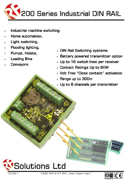
200 Series Industrial DIN RAIL• Industrial machine switching• Home automation,• Light switching,• Flooding lighting,• DIN Rail Switching systems• Pumps, Hoists,• Battery powered <strong>transmitter</strong> option• Loading Bins• Up to 16 switch lines per receiver• Conveyors• Contact Ratings Up to 6KW• Volt Free “Close contact” activation• Range up to 300m• Up to 8 channels per <strong>transmitter</strong><strong>Solutions</strong> LtdDS <strong>202</strong>-1 ©2009 REG No 277 4001, Lewes, England. Page 1
<strong>202</strong> Industrial SeriesReceiver• 16 outputs• The receiver learns up to 48 <strong>transmitter</strong>s• Momentary outputTransmitter• Flexible learn procedure allows “one to one”, “one to many “ and“many to many” switching capability.• LED indication to show active outputs.• Supplied with bulkhead mounting antenna• 8 No volt inputs via screw terminal• Simply connect a switch, relay or contactor via the screw terminalsand close the contact to send a transmission.• On board battery with up to 3 years life span (back-up life)• External input for 9-24Vdc if required• Auto Transmit feature to ensure reliability• Range up to 300m• Supplied with bulkhead mounting antennaOrderingRelay Modules• Supplied with connection cables to receiver board• 230 - 4 Industrial level Relays• 30A at 230V (5000W) per relay• Change over contacts: Normally Open and Normally Closed• 215 - 8 High quality relays• 6A at 230V (1200w) per relay• Change over contacts: Normally Open and Normally Closed• 216 - 4 High quality relays• 6A at 230V (1200w) per relay• Change over contacts: Normally Open and Normally ClosedPart NumbersDescriptionRange(Metres)Freq(MHz)<strong>202</strong>-433F Transmitter 300 433.92210-433F Receiver 300 433.92230 / 215 / 230 Relay Boards N/A N/ADS <strong>202</strong>-1 ©2009 REG No 277 4001, Lewes, England. Page 2
<strong>202</strong> Industrial SeriesInstallation guideTransmitter set-upPowerThe <strong>202</strong> range of <strong>transmitter</strong>s come with an on board lithium battery (CR2032) and connection for anexternal DC source if required.External power in the range 9—24V DC may be applied via the screw terminal marked DC input (Fig 1.1)For estimated battery life figures see technical specifications page 7.WiringInstallation of the <strong>202</strong> <strong>transmitter</strong> range is simply a case of connecting the input screw terminals to yourchosen switch and if required connecting the power supplyNOTE: Inputs are volt free, DO NOT connect power to the inputs.Antenna MountingThe <strong>202</strong> comes with a BNC connector.Auto TX LinkThe <strong>202</strong> can be set to automatically transmit a “watchdog” signal, The Auto Tx feature sends the statusof all inputs to all associated receivers at a random time between 5 and 10seconds. The receiver will dropout its signal fail relay within 20seconds of no communication.The <strong>202</strong> has three Auto TX options: Off, Default and Forced.• Off—Remove the jumper link from the pins; the Auto TX is completely disabled.• Default—Cover pins 2-3 with the jumper link; the auto TX will only function when an external powersource is added. If external power fails the <strong>202</strong> will stop the auto Tx but will otherwise operate normally.• Forced—Cover pins 1-2; the auto TX with transmit at all times irrespective of the power source.(CR2032 battery or external)DS <strong>202</strong>-1 ©2009 REG No 277 4001, Lewes, England. Page 3
<strong>202</strong> Industrial SeriesInstallation guide—continuedReceiver set-upPowerThe 210-433F receiver is powered by 12V or 24V DC, this is connected as shown below.A regulated power supply capable of delivering at least 1 Amp is required (page).For power consumption figures see Technical Specifications pageWiringInstallation of the 210 receiver range requires; connecting the power supply as shown below andconnecting your chosen relay output board(s).DC Power in+24V+12V0VFig 1.2Learn Button Learn LED (17)Connect either 12 or 24NEVER bothConnectors for cables toRelay boards4 3211 3 5 7 9 11 13 152 4 6 8 10 12 14 16Momentary or Latchingselection links 1-16Output indicator LEDs1-16DS <strong>202</strong>-1 ©2009 REG No 277 4001, Lewes, England. Page 4
<strong>202</strong> Industrial SeriesPairing ProcessDecide which input you wish to operate which output and follow the below process, bearing in mindthat LEDs on the 210-433F correspond directly to the relay out number on a connected relay board:1. Power the 210 receiver. On first use it will be in factory default mode—all channel LEDsflashing alternately on/off.2. Power the <strong>202</strong> <strong>transmitter</strong> which you want to pair. Send a signal, by closing a switch orcontact across any input. Ensure that the 210 receiver comes out of factory default and flashesLED 3 briefly.3. Once all LEDs are out, press the 210 receiver’s learn button once briefly then (all LEDs willflash on then go out leaving only LED1 lit), tap the learn button repeatedly to scroll through theLEDs 1-16, stop at the desired LED number leaving that numbered LED lit.4. Momentarily close the contact or switch on the <strong>202</strong> <strong>transmitter</strong> input that you wish topair to the selected 210 receiver output.5. The receiver’s output LED should flash to confirm that your chosen input is now paired tothe output required.6. Pairing is now complete for one channel, repeat for any other inputs or outputs required.Erasing the Receiver Memory1. To completely erase the 210 receiver memory, press and hold the learn button2. The learn LED (LED17) should illuminate (Fig 1.2)3. Hold the learn button for approximately 10seconds4. When the LED (LED17) extinguishes the memory is erased and the 210 receiver will return tofactory default mode.Note: it is not possible to erase individual <strong>transmitter</strong>s or inputs.Auto TxWhen using the <strong>202</strong>-433F channel 16 becomes permanently active. It will turn off if an Auto Tx signalform the <strong>202</strong>-433F fails to get through or if external power supply fails on the <strong>202</strong>-433F Transmitter.AUTO TX fail on power supply fail can be disabled by switching the AUTO TX jumper link on the <strong>202</strong>-433F to the FORCE position.NOTE: The Auto TX Channel does not need to be paired. If another pairing is made on this channel enablingthe Auto Tx feature would override it.DS <strong>202</strong>-1 ©2009 REG No 277 4001, Lewes, England. Page 5
<strong>202</strong> Industrial SeriesRelay Module Set-upPowerRelay modules are powered by the 210 Receiver and require no external supply.Connecting to a 210 receiverThe Relay boards plug into the 210 receiver using the connectors indicated below and on the previous page.Wiring3 different relay modules are available for use with a 210 Receiver, these all work in the same manner; operatinga changeover contact the example below shows a 215 relay board.DS <strong>202</strong>-1 ©2009 REG No 277 4001, Lewes, England. Page 6
<strong>202</strong> Industrial SeriesTechnical Specifications<strong>202</strong> TransmittersPart: <strong>202</strong>-433FDimensions:Within DIN RAIL Bracket: 75 x 82mm. PCB Only: 75 x 72mmTemperature Range:Electrical CharacteristicsMinTypicalMaxUnitsSupply Voltage: 9-24V Supply 9 12 24 VAntenna Output Lead Impedance 50 OhmsMinimum input activation time to trigger transmission 50 ms433MHz VersionSupply Current: Quiescent ~0 mASupply Current: Transmitting Data ~15 mAStorage -10 to +70 o C. Operating: 0 to +55 o CBattery Life - ESTIMATESBattery life figures have been carefully tested however, they may vary greatly depending on individual installationconditions such as temperature, and other factors.Part Number / descriptionBatteryCapacityBattery life(Auto Tx Forcedenabled)<strong>202</strong>-433F - On Board CR2032 220mAh 8 days<strong>202</strong>-433F - 9V PP3 900mAh 4 Weeks<strong>202</strong>-433F - 12V Lead Acid ~ Estimate ~ 6MonthsBattery LifeAuto Tx off20 switches p/day1 YearBattery shelf life*Battery shelf life**Shelf life of the battery will expire before it is depletedDS <strong>202</strong>-1 ©2009 REG No 277 4001, Lewes, England. Page 7
<strong>202</strong> Industrial SeriesTechnical Specifications—contdcontd210 ReceiversPart: 210-433FDimensions:Within DIN Rail: 138 x 82 mm (PCB: 133 x 72mm)Temperature Range:Electrical CharacteristicsMinTypicalMaxSupply Voltage: 12V Supply 10 12 16 VSupply Voltage: 24V Supply 21 24 30 VSupply Current : Quiescent 25 mAUnitsTime from Tx Switch depressed to 210Rx output 100 mSecsTime from Tx Switch release to Decoder output 200 mSecsSwitched output Voltage (I out = 1mA)Logic Low 0 0.2 0.8 VLogic High 3.5 3.8 5 VCurrent Consumption433MHz VersionSupply Current: Quiescent 10 mAAll relays ActiveStorage : -10 to +70o Celsius. Operating: 0 to +55o Celsius.mADS <strong>202</strong>-1 ©2009 REG No 277 4001, Lewes, England. Page 8
<strong>202</strong> Industrial SeriesTechnical Specifications– contdRelay Modules215 Relay Output ModulePart: 2158 relay outputs rated at 230Vac ,12A peak and 5A continuous current.Dimensions: Within DIN Rail: 93 x 82 mm (PCB: 90 x 72mm)Electrical CharacteristicsSupply VoltageStorage Temperature: -10 to +70 o Celsius. Operating Temperature: 0 to +55 o Celsius.*The relay contacts in this unit are for functional use only and must not be used for isolation purposesMinTypicalFrom 210Rx moduleMaxRelay* output Rating (type KB12) at 230Vac 5 12 AUnits216 Relay Output ModulePart: 2164 relay outputs rated at 230Vac ,12A peak and 5A continuous current.Dimensions: Within DIN Rail: 93 x 82 mm (PCB: 90 x 72mm)Storage Temperature: -10 to +70 o Celsius. Operating Temperature: 0 to +55 o Celsius.Electrical CharacteristicsSupply Voltage*The relay contacts in this unit are for functional use only and must not be used for isolation purposesMinTypicalFrom 210Rx moduleMaxRelay* output Rating (type KB12) at 230Vac 5 12 AUnits230 Relay Output ModulePart: 2304 relay (type K7SFA12) outputs rated for up to 30A at 230Vac.Dimensions: Within DIN Rail: 115 x 82 mm (PCB: 109 x 72mm)Storage Temperature: -10 to +70 o Celsius. Operating Temperature: 0 to +55 o Celsius.Electrical CharacteristicsSupply VoltageRelay output Rating @ 230Vac*@ 12VdcMinTypicalMaxUnitsFrom 210Rx module30 A20 A*The relay contacts in this unit are for functional use only and must not be used for isolation purposesDS <strong>202</strong>-1 ©2009 REG No 277 4001, Lewes, England. Page 9
<strong>202</strong> Industrial SeriesAntenna and RangeConnecting an Antenna210-433FThe 210 Receiver has a 100mm flying lead cable (50ohm) with a panel mount BNC socket provided to mounton an enclosure. This cable may be extended however please note that typically there is a 50% range reductionwith every 3metres of coax cable used!For increasing range performance a +3dB gain antenna is available. This is supplied with wall mountingbracket and 2metres of coax cable, it plugs in directly to the 210 Receiver BNC connector - Part NumberMB450-BNC<strong>202</strong>-433FThe <strong>202</strong>-433F has a bulk head mounting BNC connector for connecting the antenna (supplied). This can alsobe used to connect an extension cable and remote antenna. It is important to note that typically there is a50% range reduction with every 3metres of coax cable used!RangeThe antenna choice and position directly controls the system range. Keep it clear of other metal in the system.The best position by far, is protruding vertically from the top of the product. This is often not desirablefor practical reasons and thus a compromise may be needed. Note that the space around the antenna is asimportant as the antenna itself. All radio systems are dependant on a radio signal being received throughairspace.The range quoted is the optimal in direct line of sight without obstacles and in good atmospheric conditions.Range is affected by many things, for example local environmental conditions, atmospheric conditions, interferencefrom other radio <strong>transmitter</strong>s. For evaluating the local environment please see our <strong>RF</strong> Meter(DS006)In very worse case applications the range quoted may be reduced below 30% of the optimal range stated.Signal integrityIn systems where many encoders are in close proximity there may be occasions when, due to signal overlaybetween encoders, it is difficult or impossible to guarantee system integrity. In such circumstances it is theresponsibility of the installer to ensure that the system performance is adequate for the purposes of theinstallation.Information availabilityAll products are supplied with their relevant <strong>datasheet</strong>s. These are also available for download from the websiteor on request from <strong>RF</strong> <strong>Solutions</strong> Ltd.DS <strong>202</strong>-1 ©2009 REG No 277 4001, Lewes, England. Page 10
<strong>202</strong> Industrial SeriesCompatibility:<strong>202</strong>-433Fcan also be used with <strong>RF</strong> <strong>Solutions</strong> product:HORNET-RX, 210-433F, RDF1210-433Fcan be used with <strong>transmitter</strong>s:HORNET-TXn, FIREFLY-TXn, 200-433F210-433Fcan be used with Relay boards:215, 230, 216Other products in this series:200-525N- Long Range Transmitter (1km)210-525N- Long range Receiver (for use with the above)200-458F- Very long range <strong>transmitter</strong> (6km)210-458F- Very Long range Receiver (for use with the above)R F <strong>Solutions</strong> Ltd.,Unit 21, Cliffe Industrial Estate,Lewes, E. Sussex. BN8 6JL. England.Email : sales@rfsolutions.co.ukhttp://www.rfsolutions.co.ukTel: +44 (0)1273 898 000 Fax: +44 (0)1273 480 661DS <strong>202</strong>-1 ©2009 REG No 277 4001, Lewes, England. Page 11


