202 transmitter datasheet - RF Solutions
202 transmitter datasheet - RF Solutions
202 transmitter datasheet - RF Solutions
You also want an ePaper? Increase the reach of your titles
YUMPU automatically turns print PDFs into web optimized ePapers that Google loves.
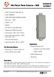
<strong>202</strong> Industrial SeriesAntenna and RangeConnecting an Antenna210-433FThe 210 Receiver has a 100mm flying lead cable (50ohm) with a panel mount BNC socket provided to mounton an enclosure. This cable may be extended however please note that typically there is a 50% range reductionwith every 3metres of coax cable used!For increasing range performance a +3dB gain antenna is available. This is supplied with wall mountingbracket and 2metres of coax cable, it plugs in directly to the 210 Receiver BNC connector - Part NumberMB450-BNC<strong>202</strong>-433FThe <strong>202</strong>-433F has a bulk head mounting BNC connector for connecting the antenna (supplied). This can alsobe used to connect an extension cable and remote antenna. It is important to note that typically there is a50% range reduction with every 3metres of coax cable used!RangeThe antenna choice and position directly controls the system range. Keep it clear of other metal in the system.The best position by far, is protruding vertically from the top of the product. This is often not desirablefor practical reasons and thus a compromise may be needed. Note that the space around the antenna is asimportant as the antenna itself. All radio systems are dependant on a radio signal being received throughairspace.The range quoted is the optimal in direct line of sight without obstacles and in good atmospheric conditions.Range is affected by many things, for example local environmental conditions, atmospheric conditions, interferencefrom other radio <strong>transmitter</strong>s. For evaluating the local environment please see our <strong>RF</strong> Meter(DS006)In very worse case applications the range quoted may be reduced below 30% of the optimal range stated.Signal integrityIn systems where many encoders are in close proximity there may be occasions when, due to signal overlaybetween encoders, it is difficult or impossible to guarantee system integrity. In such circumstances it is theresponsibility of the installer to ensure that the system performance is adequate for the purposes of theinstallation.Information availabilityAll products are supplied with their relevant <strong>datasheet</strong>s. These are also available for download from the websiteor on request from <strong>RF</strong> <strong>Solutions</strong> Ltd.DS <strong>202</strong>-1 ©2009 REG No 277 4001, Lewes, England. Page 10


