202 transmitter datasheet - RF Solutions
202 transmitter datasheet - RF Solutions
202 transmitter datasheet - RF Solutions

You also want an ePaper? Increase the reach of your titles
YUMPU automatically turns print PDFs into web optimized ePapers that Google loves.
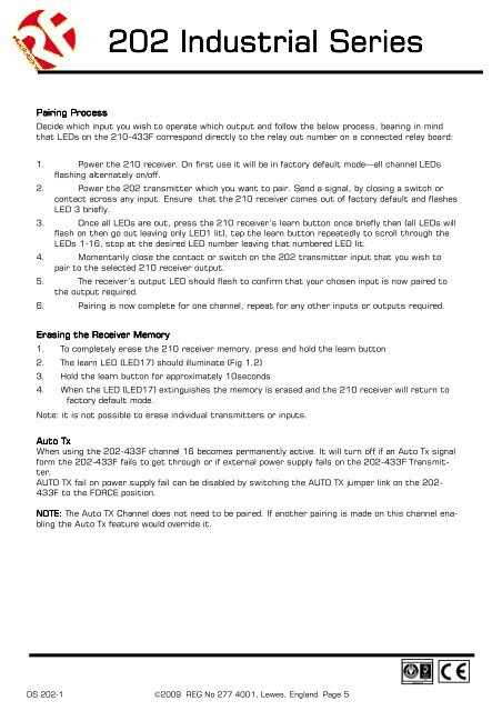
<strong>202</strong> Industrial SeriesPairing ProcessDecide which input you wish to operate which output and follow the below process, bearing in mindthat LEDs on the 210-433F correspond directly to the relay out number on a connected relay board:1. Power the 210 receiver. On first use it will be in factory default mode—all channel LEDsflashing alternately on/off.2. Power the <strong>202</strong> <strong>transmitter</strong> which you want to pair. Send a signal, by closing a switch orcontact across any input. Ensure that the 210 receiver comes out of factory default and flashesLED 3 briefly.3. Once all LEDs are out, press the 210 receiver’s learn button once briefly then (all LEDs willflash on then go out leaving only LED1 lit), tap the learn button repeatedly to scroll through theLEDs 1-16, stop at the desired LED number leaving that numbered LED lit.4. Momentarily close the contact or switch on the <strong>202</strong> <strong>transmitter</strong> input that you wish topair to the selected 210 receiver output.5. The receiver’s output LED should flash to confirm that your chosen input is now paired tothe output required.6. Pairing is now complete for one channel, repeat for any other inputs or outputs required.Erasing the Receiver Memory1. To completely erase the 210 receiver memory, press and hold the learn button2. The learn LED (LED17) should illuminate (Fig 1.2)3. Hold the learn button for approximately 10seconds4. When the LED (LED17) extinguishes the memory is erased and the 210 receiver will return tofactory default mode.Note: it is not possible to erase individual <strong>transmitter</strong>s or inputs.Auto TxWhen using the <strong>202</strong>-433F channel 16 becomes permanently active. It will turn off if an Auto Tx signalform the <strong>202</strong>-433F fails to get through or if external power supply fails on the <strong>202</strong>-433F Transmitter.AUTO TX fail on power supply fail can be disabled by switching the AUTO TX jumper link on the <strong>202</strong>-433F to the FORCE position.NOTE: The Auto TX Channel does not need to be paired. If another pairing is made on this channel enablingthe Auto Tx feature would override it.DS <strong>202</strong>-1 ©2009 REG No 277 4001, Lewes, England. Page 5