202 transmitter datasheet - RF Solutions
202 transmitter datasheet - RF Solutions
202 transmitter datasheet - RF Solutions

You also want an ePaper? Increase the reach of your titles
YUMPU automatically turns print PDFs into web optimized ePapers that Google loves.
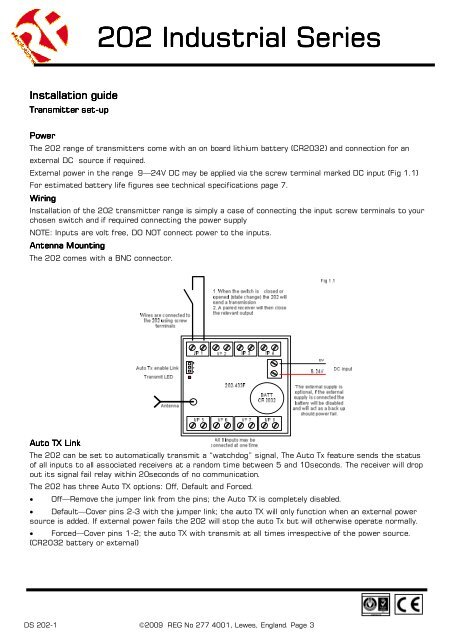
<strong>202</strong> Industrial SeriesInstallation guideTransmitter set-upPowerThe <strong>202</strong> range of <strong>transmitter</strong>s come with an on board lithium battery (CR2032) and connection for anexternal DC source if required.External power in the range 9—24V DC may be applied via the screw terminal marked DC input (Fig 1.1)For estimated battery life figures see technical specifications page 7.WiringInstallation of the <strong>202</strong> <strong>transmitter</strong> range is simply a case of connecting the input screw terminals to yourchosen switch and if required connecting the power supplyNOTE: Inputs are volt free, DO NOT connect power to the inputs.Antenna MountingThe <strong>202</strong> comes with a BNC connector.Auto TX LinkThe <strong>202</strong> can be set to automatically transmit a “watchdog” signal, The Auto Tx feature sends the statusof all inputs to all associated receivers at a random time between 5 and 10seconds. The receiver will dropout its signal fail relay within 20seconds of no communication.The <strong>202</strong> has three Auto TX options: Off, Default and Forced.• Off—Remove the jumper link from the pins; the Auto TX is completely disabled.• Default—Cover pins 2-3 with the jumper link; the auto TX will only function when an external powersource is added. If external power fails the <strong>202</strong> will stop the auto Tx but will otherwise operate normally.• Forced—Cover pins 1-2; the auto TX with transmit at all times irrespective of the power source.(CR2032 battery or external)DS <strong>202</strong>-1 ©2009 REG No 277 4001, Lewes, England. Page 3