Therm-A-Gap Gel 30 Reliability Report - Parker
Therm-A-Gap Gel 30 Reliability Report - Parker
Therm-A-Gap Gel 30 Reliability Report - Parker

Create successful ePaper yourself
Turn your PDF publications into a flip-book with our unique Google optimized e-Paper software.
1.0 IntroductionThe purpose of the document is to examine the physical and thermal reliability of thishigh performance gap filler. Samples of manufacturing batches of <strong>Gel</strong> <strong>30</strong> weresubjected to long term heat aging, high temperature weight loss, volatile silicone content,vertical gap slump testing and thermal impedance versus pressure.2.0 Long-Term Aging2.1 PurposeLong term aging was performed on <strong>Gel</strong> <strong>30</strong> between aluminum nitridesubstrates to evaluate the thermal performance reliability over time. Thematerial was subjected to an extended dwell time of 1000-hrs at 125 o C, 500cycles temperature cycling from -40 o C to 125 o C, and long term heat andhumidity aging at 85 o C/ 85% relative humidity.2.2 Materials2.2.1 Twenty-two 1.25” x 1.25” x 0.060” aluminum nitride substrates2.2.2 Teflon Shims, 0.060” thick2.2.3 22 clamps2.2.4 Cincinnati Subzero model ZH-8-1-H1A0, humidity chamber2.2.5 Sun Electronics Systems PTL-001 Temperature cycling system.(-40 o C to 125 o C; 10-min ramp; 10-min dwell times.2.3 Sample Preparation2.3.1 0.5-cc samples of <strong>Gel</strong> <strong>30</strong> material were dispensed onto the center ofaluminum nitride substrates.2.3.2 The 0.060” shims were placed at the edges of the substrate.2.3.3 A second aluminum nitride substrate was placed on top of the material.2.3.4 A clamp was placed onto the assembly to hold the substrates at a constantthickness of 0.060”2.3.5 The above procedure was repeated for 11 sample assemblies.2.4 Test Procedure2.4.1 The assemblies were removed from their clamps and thermal grease wasapplied to the outside of the aluminum nitride substrates.2.4.2 The samples are tested initially for thermal impedance at 50 o C and 50-PSIper ASTMD5470.2.4.3 The thermal grease was gently removed from the outside of the assembliesand the clamps replaced.2.4.4 Five samples were placed into a 125 o C oven, three samples were placed intothe temperature cycling chamber and three were placed into a humiditychamber.2.4.5 After 500-hrs of dwell time, the samples were removed from their respectiveenvironments, allowed to equilibrate at room temperature for 2-hrs, and retestedfor thermal impedance.Page 3 of 12Rev. Dwww.chomerics.com
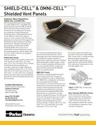
2.4.6 Once tested, the samples were returned to the respective ovens and theprevious step was repeated at 1000-hrs of total dwell time.2.5 ResultsFigure 1: Heat aged <strong>Therm</strong>al Impedance versus Time1.2Heat & Humidity Aging: 85 o C/85%RH1.0<strong>Therm</strong>al Impedance, C‐in 2 /W0.80.60.40.20.00 100 200 <strong>30</strong>0 400 500 600 700 800 900 1000Dwell Time, hrsFigure 2: Heat & Humidity aged <strong>Therm</strong>al Impedance versus TimePage 4 of 12Rev. Dwww.chomerics.com
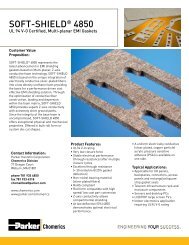
1.2Temperature Cycling1.0<strong>Therm</strong>al Impedance, C‐in 2 /W0.80.60.40.20.03.0 Total Mass Loss0 100 200 <strong>30</strong>0 400 500 600CyclesFigure 3: <strong>Therm</strong>al Impedance versus Temperature Cycling (-40 o C to 125 o C)3.1 PurposeThis test is intended to provide data on the temperature stability of <strong>Gel</strong> <strong>30</strong>and the volatile silicone content of the product. Volatile silicone is ofconcern due to its ability to migrate and cause problems in electronicsapplications. The material was tested both using in-house test method and byan independent outside laboratory.3.2 Materials3.2.1 <strong>Therm</strong>ogravimetric analyzer Model 2950 TGA V5.4A3.2.2 <strong>30</strong>-cc syringe of <strong>Gel</strong> <strong>30</strong>3.3 Test Procedure3.3.1 <strong>Gel</strong> <strong>30</strong> material was dispensed in to an aluminum TGA test pan.3.3.2 The sample is subjected to 125 o C for 3-hrs in a nitrogen environment and thesample weight loss is recorded.3.3.3 A Sample syringe of <strong>Gel</strong> <strong>30</strong> is sent to a certified independent laboratory toundergo a mass loss and collected volatile condensable materials analysisaccording to ASTM E-595.3.3.3.1 Samples are subjected to 125 o C dwell for 24-hrs at 7x10 -3 Pa.Page 5 of 12Rev. Dwww.chomerics.com
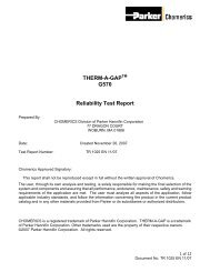
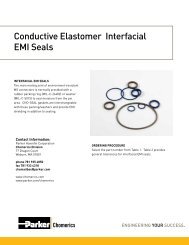
3.4 ResultsSample: XTS-80<strong>30</strong>Size: 111.5920 mgMethod: 125°C - Iso 3 hrs.TGAFile: C:...\ptl08 092519 80<strong>30</strong> TML.001Operator: djwRun Date: 4-Sep-08 11:36Instrument: 2950 TGA V5.4A99.9899.97Weight (%)99.960.06% wt loss99.95Residue:99.94% 3 hrs @ 125°C(111.5mg)99.9499.9<strong>30</strong> 20 40 60 80 100 120 140 160 180Time (min)Universal V3.9A TA InstrumentsFigure 4: <strong>Therm</strong>ogravimetric Analysis at 125 o C for 3-hrsThe National Aeronautics & Space Associations (NASA) criteria for low outgasmaterials limit materials’ (TML) Total Mass Loss to 1.0% and Collected VolatileCondensable Material (CVCM) to 0.10%. The table below contains the test results for<strong>Gel</strong> <strong>30</strong>.Outgassing Results%Total Mass Loss 0.15%CVCM 0.05Table 1: Independent Laboratory Mass Loss Results4.0 Vertical <strong>Gap</strong> Slump Testing4.1 PurposeThis test is intended to simulate the gravitational effects on the mechanicalintegrity of <strong>Gel</strong> <strong>30</strong>, when dispensed on an application with a gapperpendicular to the gravitational force. It demonstrates the physicalintegrity and ability of <strong>Gel</strong> <strong>30</strong> to maintain its position in vertical applicationswith varying gap thickness at 85 o C.4.2 Materials4.2.1 Six 4”x 4” glass panel4.2.2 0.010” , 0.075” and 0.140” metal shims4.2.3 12 clampsPage 6 of 12Rev. Dwww.chomerics.com
4.3 Test Procedure4.3.1 Three samples of <strong>Gel</strong> <strong>30</strong> were dispensed onto a glass panels 0.5” apart, with1”separation from the top edge of the glass.4.3.2 0.010” shims were placed at the edges of the panel and a second clean glasspanel was placed on top. The <strong>Gel</strong> <strong>30</strong> samples compressed between the glasspanels result in a 0.75” diameter surface contact area on each surface.4.3.3 Two clamps are fastened to the left and right side of the assembly.4.3.4 The previous steps are repeated for assemblies made with 0.075” and 0.140”Shims.4.3.5 The three assemblies were placed into an 85ºC oven for with the panelsoriented vertically, so the panels would be perpendicular to force of gravity.4.3.6 After a 500-hr dwell time, the distance traveled from the sample’s originalposition was recorded.4.4 Results<strong>Gap</strong>(inches)Vertical SlumpDistance (inches)0.010 00.075 00.140 0Table 2: Linear Travel After 500-hrs @ 85 o C5.0 <strong>Therm</strong>al Impedance versus Pressure5.1 PurposeThis test is intended to determine the effects of pressure on the thermalimpedance of <strong>Therm</strong>-A-<strong>Gap</strong> <strong>Gel</strong> <strong>30</strong> and determine the minimum bond lineachievable with this material.5.2 Materials5.2.1 <strong>30</strong>cc syringe of <strong>Gel</strong> <strong>30</strong>5.2.2 <strong>Therm</strong>al Interface Material Tester TIM Tester 1<strong>30</strong>05.3 Test Procedure5.3.1 15-g of <strong>Therm</strong>-A-<strong>Gap</strong> <strong>Gel</strong> <strong>30</strong> was dispensed onto the tester surface.5.3.2 The samples are tested for thermal impedance at 50 o C and 20-PSI per ASTMD5470.5.3.3 The previous steps are repeated for test pressures of <strong>30</strong>, 50, 100, 150, 200, and<strong>30</strong>0-PSI.Page 7 of 12Rev. Dwww.chomerics.com
5.4 Results6.0 <strong>Therm</strong>al Impedance versus ThicknessFigure 5: <strong>Therm</strong>al Impedance versus Pressure6.1 PurposeThis test is intended to determine the effects of material dispensed thicknesson the thermal Impedance of <strong>Therm</strong>-A-<strong>Gap</strong> <strong>Gel</strong> <strong>30</strong>.6.2 Materials6.2.1 <strong>30</strong>cc syringe of <strong>Gel</strong> <strong>30</strong>6.2.2 <strong>Therm</strong>al Interface Material Tester TIM Tester 1<strong>30</strong>06.3 Test Procedure6.3.1 15-g of <strong>Therm</strong>-A-<strong>Gap</strong> <strong>Gel</strong> <strong>30</strong> was dispensed onto the tester surface.6.3.2 The samples are tested for thermal impedance at 50 o C and a set height of0.175” according to ASTM D5470.6.3.3 The previous steps are repeated for test thickness of 0.140”, 0.090”, 0.050”,0.025” and 0.003”.Page 8 of 12Rev. Dwww.chomerics.com
6.4 ResultsFigure 6: <strong>Therm</strong>al Impedance versus Thickness7.0 Vibration Testing7.1 PurposeThis test was used to determine the effect of vibration on the thermalperformance of <strong>Gel</strong> <strong>30</strong>.7.2 Materials7.2.1 Ceramic substrates 1.25”x1.25”x0.060”7.2.2 plastic shims; 3/8” diameter with varying thickness7.2.3 A <strong>30</strong>-cc syringe of gel <strong>30</strong> with 10g/min flow rate7.2.4 A <strong>30</strong>-cc syringe of gel <strong>30</strong> with 20g/min flow rate7.3 Sample Preparation7.3.1 Three samples at each thickness are prepared for both flow rate materials.7.3.2 Dispense the appropriate amount of <strong>Gel</strong> <strong>30</strong> onto the center of a ceramicsubstrate according to the weights listed in the table below.SamplethicknessmaterialWeight, gMin. Bond line 0.21840.25mm 0.19361.5mm 1.16133mm 2.3226Table 3: Sample preparation weightsPage 9 of 12Rev. Dwww.chomerics.com
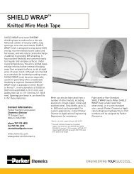
7.3.3 Place the appropriate shims at the corners of the substrate. For minimumbond line samples, no shims are needed.7.3.4 A second ceramic substrate was place on top of the material.7.3.5 A small clamp was placed onto the assembly to hold the shims in place andmaintain the sample at the appropriate thickness.7.3.6 This sample preparation procedure was repeated for 3 samples of both the10g/min and 20g/min batches of <strong>Gel</strong> <strong>30</strong> at minimum bond line, 0.25mm,1.5mm, and 3mm sample thicknesses.7.4 Test procedure7.4.1 The sample assemblies were carefully removed from their clamps andthermal grease was applied to the outside of the ceramic substrates.7.4.2 The samples were tested initially for thermal impedance at 50 o C and 50-PSIper ASTM D5470.7.4.3 After recording the thermal impedance, the samples were removed from thetester, the thermal grease was removed from the outside of the assembles,and the clamps were replaced.7.4.4 The samples were then sent to an outside testing facility and subjected to 8-hrs of vibration, ramping between 10 to 1000Hz in both the X and Y axis.The temperature was maintained at 85 o C.7.4.5 After being subjected to the vibration conditions the samples were tested forthermal impedance following steps 2.6.4.1 to 2.6.4.3.7.5 ResultsFigure 7: Vibration results for 10g/min <strong>Gel</strong> <strong>30</strong>Page 10 of 12Rev. Dwww.chomerics.com
Figure 8: Vibration results for 20g/min <strong>Gel</strong> <strong>30</strong>8.0 Conclusion<strong>Therm</strong>-A-<strong>Gap</strong> <strong>Gel</strong> <strong>30</strong> is a one-component, cross-linked gel material. This cross-linking structureprovides superior performance and long term thermal stability over conventional thermal greasematerials. It demonstrated minimal weight loss of less than 0.10% after 3hrs at 125 °C based onin-house thermogravimetric analysis (Figure 4). This result was confirmed by a certifiedindependent laboratory test, which resulted in 0.15% total mass loss after 24-hr dwell at 125 o C.The thermal performance of <strong>Gel</strong> <strong>30</strong> was examined after subjection to multiple environmentalstress tests. Other than an initial decrease due to a surface wetting phenomenon, the thermalimpedance of the material was unaffected by 1000-hrs dwell at 125 o C, 1000-hrs dwell at85 o C/85% relative humidity, and 500 temperature cycles from -40 o C to 125 o C. The initialthermal impedance dropped by 7%, 10% and 7% respectively. The material displays resiliencyunder physical stress, as well. The thermal impedance of the material was unaffected by 8-hrvibration ramping from 10 to 1000-Hz at 85 o C.Based on these results, <strong>Therm</strong>-A-<strong>Gap</strong> <strong>Gel</strong> <strong>30</strong> demonstrates superior long term reliability andresistance to thermal oxidative degradation associated with continuous application temperaturesof up to 125 o C. The material also maintains physical integrity in vertical gap applications andwhen subjected to high frequency vibration application environments.Footnote:The user, through its own analysis and testing, is solely responsible for making the final selection of the systemand components and assuring that all performance, endurance, maintenance, safety and warning requirementsof the application are met. The user must analyze all aspects of the application, follow applicable industrystandards, and follow the information concerning the product in the current product catalog and in any othermaterials provided from <strong>Parker</strong> or its subsidiaries or authorized distributors.The reported physical properties for GEL<strong>30</strong> represent material as manufactured by Chomerics. Repackagingof GEL<strong>30</strong> is not recommended and may result in a deviation from these properties.Page 11 of 12Rev. Dwww.chomerics.com
Appendix A: Typical PropertiesPage 12 of 12Rev. Dwww.chomerics.com