THERM-A-GAP G570 Reliability Test Report - Parker
THERM-A-GAP G570 Reliability Test Report - Parker
THERM-A-GAP G570 Reliability Test Report - Parker
- No tags were found...
Create successful ePaper yourself
Turn your PDF publications into a flip-book with our unique Google optimized e-Paper software.
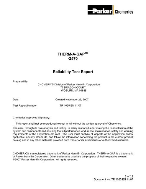
<strong>THERM</strong>-A-<strong>GAP</strong> TM<strong>G570</strong><strong>Reliability</strong> <strong>Test</strong> <strong>Report</strong>Prepared By:CHOMERICS Division of <strong>Parker</strong> Hannifin Corporation77 DRAGON COURTWOBURN, MA 01888Date: Created November 26, 2007<strong>Test</strong> <strong>Report</strong> Number: TR 1025 EN 11/07Chomerics Approved Signatory:This report shall not be reproduced except in full without the written approval of Chomerics.The user, through its own analysis and testing, is solely responsible for making the final selection of thesystem and components and assuring that all performance, endurance, maintenance, safety and warningrequirements of the application are met. The user must analyze all aspects of the application, followapplicable industry standards, and follow the information concerning the product in the current productcatalog and in any other materials provided from <strong>Parker</strong> or its subsidiaries or authorized distributors.CHOMERICS is a registered trademark of <strong>Parker</strong> Hannifin Corporation. <strong>THERM</strong>-A-<strong>GAP</strong> is a trademarkof <strong>Parker</strong> Hannifin Corporation. Other trademarks used are the property of their respective owners.©2007 <strong>Parker</strong> Hannifin Corporation. All rights reserved.1 of 12Document No. TR 1025 EN 11/07
TABLE OF CONTENTS1.0 Introduction 41.1 Purpose1.2 Sample Set-Up Summary2.0 Thermal Shock 42.1 Introduction and References2.2 Procedure2.3 Acceptance Criteria3.0 Steady Temperature <strong>Test</strong> 53.1 Introduction and Reference3.2 Procedure4.0 Damp Heat Cycle 64.1 Introduction and Reference4.2 Procedure5.0 <strong>Test</strong> Procedure 65.1 Sample Preparation5.2 Thermal Impedance5.3 Compression Deflection6.0 Results 76.1 Compression Deflection6.2 Thermal ImpedanceAppendicesA. Typical Properties 11B. Thermal Impedance vs. Pressure 122 of 12Document No. TR 1025 EN 11/07
SUMMARY OF PHYSICAL PROPERTIESList of Acronyms and InitialsTIMHSPSPRIECThermal Interface MaterialsHeat Spreader MaterialsStandard Product RequirementsInternational Electrotechnical CommissionList of DefinitionsLaboratory EnvironmentRoom TemperatureNormal PerformanceThermal Decomposition:Mechanical DecompositionVisible DecompositionA temperature between 20 and 25 o C and a relativehumidity between 40 and 60%A temperature between 20 and 25 o CFulfillment of specified performance requirementAllowed as long as the material still remains in spec. aftertestingAllowed as long as the material still remains in spec. aftertestingMinimal visible decomposition is allowed. This will befurther defined at a later date.3 of 12Document No. TR 1025 EN 11/07
1.0 Introduction1.1 PurposeThe purpose of the document is to explain the mechanical and environmental tests andthe corresponding measurements that were performed on samples of Chomericsthermally conductive gap filler <strong>THERM</strong>-A-<strong>GAP</strong> <strong>G570</strong>.1.2 Sample Set-Up SummaryThe samples were tested at seven different thicknesses. The thicknesses were 0.070,0.130, 0.160, and 0.200 inches (1.8, 3.3, 4.1, and 5.1 mm). The thermal impedance andcompression as a factor of pressure were measured for each sample. Themeasurements were taken initially and after heat aged processes. The heat agedprocesses were thermal shock; steady temperature at -30, 70, and140 o C; and dampheat cycling. Further details of these tests are given in the <strong>Test</strong> Specification forThermal Solutions, as issued by Nokia. Measurements were taken on a set of tensamples for each set of conditions. Samples subjected to damp heat cycles were sent toContech Research, 67 Mechanic St. Attleboro, MA 02703 phone number 508-226-4800D. Arpino <strong>Test</strong> <strong>Report</strong> #207029. All other measurements were performed within <strong>Parker</strong>Chomerics.2.0 Thermal Shock2.1 Introduction and ReferencesThermal shock tests can be used to thermally age materials to ensure the reliability ofmaterials or the connections between parts.2.2 ProcedureThe samples were placed within a temperature chamber at a temperature of -40 o C. Thesamples were kept at the temperature of -40 o C for two hours and then moved to achamber of temperature 85 o C. Less than three minutes passed in the process of movingthe samples between temperature chambers. The samples were kept at a temperatureof 85 o C for two hours, and then moved back to the -40 o C chamber. The samples werecycled between the -40 and 85 o C chambers five times total. After the cycling, thesamples were allowed to cool to room temperature in a laboratory environment. The finalmeasurements were carried out after a minimum of two hours to ensure normalperformance. Figure 1 depicts the thermal shock test sequence.4 of 12Document No. TR 1025 EN 11/07
.2.3 Acceptance CriteriaMinimal visible decomposition will be allowed. The acceptable level ofdecomposition is to be defined.Mechanical decomposition is allowed as long as the material still remains withinspecification after testing.Thermal decomposition is allowed as long as the material still remains withinspecification after testing.3.0 Steady Temperature <strong>Test</strong>3.1 Introduction and ReferenceThe purpose of the steady temperature test is to ensure the reliability of the samplesafter exposure to a range of air temperatures.3.2 ProcedureThe samples were placed into the test chamber at -30 o C and held for 16 hours. After the16 hours, all samples are taken out and left at room temperature. Measurements of tenof the samples for each thickness were taken after a minimum of 2 hours. The remainingsamples were placed into the test chamber and held at 70 o C for 16 hours. After the 16hours, all samples were taken out and left at room temperature. Measurements of ten ofthe samples for each thickness were taken after a minimum of 2 hours. The remainingsamples were placed into the test chamber and held at 140 o C for 16 hours. After the 16hours, the samples were taken out and left in a laboratory environment. After the twohour recovery period, the final measurements were taken in a laboratory environment totest for the normal performance of the samples.5 of 12Document No. TR 1025 EN 11/07
4.0 Damp Heat Cycle4.1 Introduction and ReferenceThe purpose of this test is to determine the reliability of the sample for use and storageunder conditions of high humidity combined with cycling temperature changes.4.2 ProcedureThe samples were sent to Contech (Attleboro, MA) for the damp heat cycle conditioning.The samples were placed in a test chamber at 25 o C and a relative humidity of 95%. Thetemperature is increased at a rate of 0.111 o C/min from 25 o C to 55 o C. The temperatureramp takes three hours, and the relative humidity is between 93 and 95%. Thetemperature is maintained at 55 o C for nine hours. After the nine hours the temperatureis decreased to 25 o C from 55 o C at a rate of 0.111 o C/min. The decrease takes threehours, and the relative humidity is between 93 and 95%. The temperature is maintainedat 25 o C for nine hours. The temperature cycling process is repeated 17 times, for a totalof 18 cycles. After the 18 cycles, the temperature is held at 25 o C and relative humidity isreduced to 75%. The samples are held at these conditions for an additional two hours.The samples were returned to Chomerics and tested after a minimum of 2 hours in alaboratory environment.5.0 <strong>Test</strong> Procedure5.1 Sample PreparationAll samples were cut to 1 in 2 (6.45 cm 2 ) discs before aging. Liners were left on and thesamples were spread out and not stacked during aging.5.2 Thermal ImpedanceTen samples were tested at 50°C and 10 PSI (0.069 MPa) of pressure for eachthickness at each aging condition per ASTM D5470.5.3 Compression DeflectionSamples were tested in a laboratory environment on a Texture Analyzer (from TextureTechnologies) per Chomerics NBD-001, which is a modified version of ASTM C165.Ten samples were tested for each thickness at each aging condition. Samples weretested at 0.025 inches/min (0.01 mm/sec) up to 70% deflection or 50kg, the limit of theload cell.6 of 12Document No. TR 1025 EN 11/07
6.0 Results6.1 Compression DeflectionLoad (lbs)1009080706050403020100Deflection vs Load - <strong>G570</strong> - 0.200 inch @ 0.025 in/min1 in 2 disc tested with 1 in 2 circular Aluminum probe0 5 10 15 20 25 30 35 40 45 50Deflection (%)Initial Temp Shock Steady Temp (-30°C) Steady Temp (70°C) Steady Temp (140°C) Damp HeatLoad (lbs)1009080706050403020100Deflection vs Load - <strong>G570</strong> - 0.160 inch @ 0.025 in/min1 in 2 disc tested with 1 in 2 circular Aluminum probe0 5 10 15 20 25 30 35 40 45 50Deflection (%)Initial Temp Shock Steady Temp (-30°C) Steady Temp (70°C) Steady Temp (140°C) Damp Heat7 of 12Document No. TR 1025 EN 11/07
Load (lbs)1009080706050403020100Deflection vs Load - <strong>G570</strong> - 0.130 inch @ 0.025 in/min1 in 2 disc tested with 1 in 2 circular Aluminum probe0 5 10 15 20 25 30 35 40 45 50Deflection (%)Initial Temp Shock Steady Temp (-30°C) Steady Temp (70°C) Steady Temp (140°C) Damp HeatLoad (lbs)140120100806040200Deflection vs Load - <strong>G570</strong> - 0.070 inch @ 0.025 in/min1 in 2 disc tested with 1 in 2 circular Aluminum probe0 5 10 15 20 25 30 35 40 45 50Deflection (%)Initial Temp Shock Steady Temp (-30°C) Steady Temp (70°C) Steady Temp (140°C) Damp Heat8 of 12Document No. TR 1025 EN 11/07
6.2 Thermal ImpedanceThermal Impedance @ 10 PSI<strong>G570</strong> 200 mil4.54.03.53.6633.773 3.7433.599 3.6524.066TI [°C-in 2 /Watt]3.02.52.01.51.00.50.0Initial Temp Shock -30°C 70°C 140°C Damp Heat CycleThermal Impedance @ 10 PSI<strong>G570</strong> 160 mil4.03.53.383 3.403 3.341 3.3523.4603.6623.0TI [°C-in 2 /Watt]2.52.01.51.00.50.0Initial Temp Shock -30°C 70°C 140°C Damp Heat Cycle9 of 12Document No. TR 1025 EN 11/07
Thermal Impedance @ 10 PSI<strong>G570</strong> 130 mil3.53.03.1763.0253.2353.0253.157 3.192TI [°C-in 2 /Watt]2.52.01.51.00.50.0Initial Temp Shock -30°C 70°C 140°C Damp Heat CycleThermal Impedance @ 10 PSI<strong>G570</strong> 70 mil2.52.02.0012.181 2.1832.111 2.078 2.137TI [°C-in 2 /Watt]1.51.00.50.0Initial Temp Shock -30°C 70°C 140°C Damp Heat CycleThermal Impedance @ 10 PSI<strong>G570</strong> 20 milTI [°C-in 2 /Watt]1.41.21.00.80.60.40.20.01.2311.2031.061 1.0831.1281.164Initial Temp Shock -30°C 70°C 140°C Damp Heat Cycle10 of 12Document No. TR 1025 EN 11/07
Appendix A: Typical PropertiesRegulatory Electrical ThermalPhysicalColorCarrierTypical PropertiesBlueA or GStandard Thicknesses, inch (mm) 0.020-0.20 (0.5-5.0)Specific Gravity 2.2Hardness, Shore 00 25Extractable Silicone % 10Continuous Use Temperature °C -55 to 200PercentDeflection atVariousPressures5 psi (34 kPa) 1010 psi (69 kPa) 1525 psi (172 kPa) 2550 psi (345 kPa) 35Thermal Impedance, °C-in²/W (°C-cm²/W) at10 psi (69 kPa) and 0.040 in (1 mm) thick1.5 (9.7)Apparent Thermal Conductivity, W/m-K 1.2Heat Capacity, J/g-K 1Coefficient of Thermal Expansion, ppm/K -250Dielectric Strength, Vac/mil (Kvac/mm) 200 (8)Volume Resistivity, ohm-cm 10 14Dielectric Constant at 1,000 kHz 6.5Dissination Factor at 1,000 kHz 0.013Flammability Rating V-0RoHS CompliantYesOutgassing, % TML (%CVCM) 0.35 (0.09)Shelf Life, years from date of manufacture 211 of 12Document No. TR 1025 EN 11/07
Appendix B: <strong>G570</strong> Thermal Impedance vs Pressure3.5Therm-A-Gap <strong>G570</strong>Thermal Impedance vs PressureImpedance [°C-in 2 /Watt]3.02.52.01.51.00.5<strong>G570</strong> 0.040"<strong>G570</strong> 0.070"<strong>G570</strong> 0.100"<strong>G570</strong> 0.130"0.00 10 20 30 40 50 60Pressure [psi]12 of 12Document No. TR 1025 EN 11/07


