CHOFORM Form-In-Place EMI Gasketing Solutions.pdf - Parker
CHOFORM Form-In-Place EMI Gasketing Solutions.pdf - Parker
CHOFORM Form-In-Place EMI Gasketing Solutions.pdf - Parker
- No tags were found...

You also want an ePaper? Increase the reach of your titles
YUMPU automatically turns print PDFs into web optimized ePapers that Google loves.
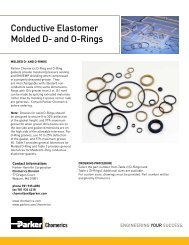
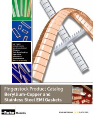
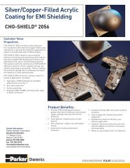
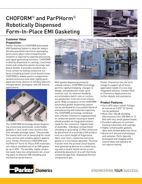
<strong>CHOFORM</strong> ® and ParPHorm ®Robotically Dispensed<strong>Form</strong>-<strong>In</strong>-<strong>Place</strong> <strong>EMI</strong> <strong>Gasketing</strong>Customer ValueProposition:<strong>Parker</strong> Chomerics <strong>CHOFORM</strong> Automated<strong>EMI</strong> <strong>Gasketing</strong> System is ideal for today’sdensely populated electronics packaging,particularly where intercompartmentalisolation is required to separate processingand signal generating functions. <strong>CHOFORM</strong>is directly dispensed on castings, machinedmetal and conductive plastic housings andboard shields. It provides excellent electricalcontact to mating conductive surfacesincluding printed circuit board traces.<strong>CHOFORM</strong> is widely used in compartmentalizedenclosures and other tightly packagedelectronic devices in military, telecom,transportation, aerospace and life scienceapplications.The <strong>CHOFORM</strong> technology allows dispensingof precisely positioned, conformablegaskets in very small cross sections thatfree valuable package space. They providethe lowest total cost of ownership for smallcross section and complex pattern applications.<strong>Parker</strong> Chomerics <strong>CHOFORM</strong> andParPHorm ® <strong>Form</strong>-<strong>In</strong>-<strong>Place</strong> (FIP) materialscan reduce installed cost of an <strong>EMI</strong> gasketby up to 60%. The durable, highly conductiveseals have low compression set, ensuringyears of effective <strong>EMI</strong> shielding andmechanical performance.With gasket dispensing primarilysoftware driven, <strong>CHOFORM</strong> technologypermits rapid prototyping, changes indesign, and production scale-up atnominal cost. Its inherent flexibilityaccommodates batch runs or continuousproduction, from ten to ten millionparts. Wide acceptance of the <strong>CHOFORM</strong>automated gasket dispensing systemcan be attributed to a successful blend ofmanufacturing and materials expertise.The <strong>CHOFORM</strong> technology combinedwith a <strong>Parker</strong> Chomerics supplied metalor conductive plastic housing or boardshield provides an integrated solutionready for the customers’ highest levelof assembly. <strong>In</strong>dividual compartmentshielding or grounding is often enhancedby placement of a secondary <strong>EMI</strong> productsuch as a short length of fingerstock,fabric over foam, conductive extrusiongasket or a microwave absorber. Thermaltransfer from the printed circuit boards’heat generating devices to a metal housingwall or board shield can be accomplishedby placement of a soft thermallyconductive gap filler, dispensed thermalcompound or gel.<strong>Parker</strong> Chomerics has the technologyto support all of theseapplication needs in a one stopintegrated solution. Contact <strong>Parker</strong>Chomerics Applications forfurther details and assistance.Product Features:• Up to 60% space saved -flangesas narrow as 0.025” (0.76mm)can be gasketed.• More than 100 dB shieldingeffectiveness from 200 MHz to 12GHz with very small gasket beads.• Excellent adhesion to commonhousing substrates and coatings.• Highly compressible gaskets,ideal with limited deflection force.• Quick turn-around of prototypesand samples. Parts typicallyprototyped and shipped withinseveral days and typically donot require tooling.
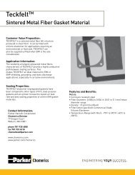
ParPHorm <strong>Form</strong>-<strong>In</strong>-<strong>Place</strong> Sealing Compounds<strong>CHOFORM</strong> and ParPHorm <strong>Form</strong>-<strong>In</strong>-<strong>Place</strong> Sealing CompoundsParPHorm is a family of non-conductive, thermal and moisturecure, form-in-place, elastomeric sealing compounds.These silicone and fluorosilicone materials provide environmental,fluid, and dust sealing of small enclosures. The productline consists of state-of-the art compounds designed tobe robotically dispensed onto small housings and then cured.Curing of the dispensed materials is done via in-line ovens at284 o F (140 o C) for 30 minutes. Dispensed bead heights rangefrom 0.018 in. (0.46 mm) to 0.062 in. (1.57 mm). Applicationadvantages of the materials are resistance to a wide varietyof fluids, excellent substrate adhesion, low hardness, andoutstanding compression set properties. Refer to Table 2b.DESCRIPTION - Thermal Cure MaterialsParPHorm S1945ParPHorm S1945 is a silicone FIP material with lower hardness(Shore A 25) and excellent compression set (21%).ParPHorm S1945 is especially designed for low closureforce applications and those requiring exceptional adhesionproperties. Due to its minimal hardness, S1945, is one of themost widely used ParPHorm materials and thus has extensiveapplication in many areas. The compound adheres wellto aluminum, phenolic resins, copper, stainless steel, glass,rigid PVC, most ceramics, and various plastics. ParPHormS1945 is compatible with air below 400 o F, ethylene glycol,nitrogen, sea (salt) water, magnesium sulfite and sulfate,citric acid, methanol, ozone, soap solutions, zinc salts andzinc sulfates, potassium chloride/nitrate, barium chloride/hydroxide/salts, sodium chloride/salts/sulfates, and glycols.ParPHorm L1938ParPHorm L1938 is a fluorosilicone FIP elastomer withShore A hardness of 45 and compression set rating of 14%.This fluorosilicone material offers additional fluid resistancecapabilities above and beyond the capabilities of S1945.FEATURES• One component thermal cure materials• Excellent resistance to a wide variety of fluids• Excellent adhesion to a wide variety of substrates• Low material and installation costsHANDLING AND CURING OF MATERIALParPHorm S1945, and L1938 are one component, thermalcure materials. Recommended cure temperature is 284 o F(140 o C) for 30 minutes. The full cure cycle of 30 minutes allowsfor immediate handling, and performance of necessaryQC tests. The use of this thermal cure, form-in-place materialreduces the need for dispensed parts storage space. Thisalso allows for immediate packaging and shipment of partsto their final destination for subsequent integration into theequipment assembly process.DESCRIPTION - Moisture Cure MaterialsParPHorm 1800ParPHorm 1800 is a non-conductive, moisture cure,form-in-place (FIP), silicone elastomer sealing material.The material provides environmental, fluid, and dustsealing of small enclosures via a compound designed tobe robotically dispensed onto small housings. Curing ofthe dispensed material is via moisture cure for 48 hours.Minimum bead size is 0.018” (0.46 mm) tall by 0.022” (0.56mm) wide. Maximum bead size is .062” (1.57 mm) tall by0.075” ((1.91 mm) wide. Application advantages of the materialare excellent adhesion, low hardness, and excellentcompression set properties. Applications for ParPHorm1800 material include handheld electronic module housings,battery cases, industrial gauges, fuel cells, and otherenclosures requiring small dispensed elastomer seals forenvironmental or fluid sealing. <strong>Parker</strong> Chomerics offersworldwide capabilities for dispensing of this material ontocustomer supplied housings. <strong>Parker</strong> Chomerics can alsoprovide supply chain management of the process andsource the housings along with ParPHorm dispensing andfinishing operations such as painting and minor mechanicalassembly.FEATURES• One component moisture cure material• Excellent resistance to a wide variety of fluids• Excellent adhesion to a wide variety of substrates• Low material and installation costsHANDLING AND CURING OF MATERIALParPHorm 1800 is a one component, moisture cure material.Recommended cure condition is 22 o C , 50% RH for 24 hours.For these same temperature and humidity conditions thetack free time is approximately 18 minutes and handling timeis 4 hours.DESIGN AND PROTOTYPINGApplication and design assistance is available to prospective customers. The specific focus of the assistance is on theexamination/identification of design issues with regard to the substrate. These design issues include: enclosure materialand surface finish, available gasket placement area, material selection, part flatness, transitions in the layout of the dispensedbead, obstructions in the design of the enclosure to the unimpeded travel of the dispense needle, and z directiondispense needs. Prototype dispensing is available on sample parts or sample coupons for customer evaluation.MATERIAL DISPENSING<strong>CHOFORM</strong> and ParPHorm are easily dispensed from a variety of commercially available gasket dispense systems. <strong>In</strong> additionto <strong>Parker</strong> Chomerics existing worldwide network of <strong>CHOFORM</strong> applicators, our <strong>CHOFORM</strong> applications engineeringgroup can provide support for material dispense needs worldwide for customers wishing to utilize their own or otherdispense equipment.Table 1a - <strong>CHOFORM</strong> Ordering <strong>In</strong>formationMaterial Part Number Material Weight Packaging Type = Size5513 19-26-5513-0850Part A 450 grams,Part B 475 grams12 fl. oz. SEMCO Tube5526 19-26-5526-0850 850 grams 12 fl. oz. Aluminum Cartridge5528 19-26-5528-0850 850 grams 12 fl. oz. Aluminum Cartridge5538 19-26-5538-0650 650 grams 12 fl. oz. Aluminum Cartridge5541 19-26-5541-0650 650 grams 12 fl. oz. Aluminum Cartridge5560 19-26-5560-0500 500 grams 12 fl. oz. Aluminum CartridgeSamples typically provided in 30cc syringesTable 1b - ParPHorm Ordering <strong>In</strong>formationMaterial Part Number Material Weight Packaging Type = Size1800 19-26-1800-0345 345 grams 12 fl. oz. Aluminum Cartridge1938 19-26-1938-0200 200 grams 6 fl. oz. SEMCO Tube1945 19-26-1945-0250 250 grams 12 fl. oz. SEMCO TubeSEMCO is a registered trademark of PRC-DeSoto, <strong>In</strong>c.
<strong>Form</strong>-<strong>In</strong>-<strong>Place</strong> Selector Guide<strong>CHOFORM</strong> - Conductive <strong>Form</strong>-<strong>In</strong>-<strong>Place</strong> GasketsTable 1 Typical Properties Test Procedure Units <strong>CHOFORM</strong> ® 5513 <strong>CHOFORM</strong> ® 5526 <strong>CHOFORM</strong> ® 5528 <strong>CHOFORM</strong> ® 5538 <strong>CHOFORM</strong> ® 5541 <strong>CHOFORM</strong> ® 5560Features -- --Excellent electricalproperties and adhesionHigh conductivity, excellentgrounding and shieldingSoft, low closure-forceCorrosion resistant,small beadCorrosion resistant,high tempExcellent corrosionresistance on AluminumConductive Filler -- -- Ag/Cu Ag Ag/Cu Ni/C Ni/C Ni/AlResin System -- -- Silicone Silicone Silicone Silicone Silicone SiliconeNumber of Components -- -- 2 1 1 1 1 1Cure System -- -- Thermal Moisture Moisture Moisture Thermal ThermalCure ScheduleTack Free TimeHandling TimeFull Cure-- --30 mins @ 140 o C30 mins @ 140 o C30 mins @ 140 o C18 mins @ 22 o C& 50% RH4 hours @ 22 o C& 50% RH24 hours @ 22 o C & 50% RH18 mins @ 22 o C& 50% RH4 hours @ 22 o C& 50% RH24 hours @ 22 o C & 50% RH18 mins @ 22 o C& 50% RH4 hours @ 22 o C& 50% RH4 hours @ 22 o C & 50% RH30 mins @ 150 o C30 mins @ 150 o C30 mins @ 150 o CHardness ASTM D 2240 Shore A 53 38 40 65 75 55Tensile Strength ASTM D 412 psi 350 80 125 325 500 165Elongation ASTM D 412 % 255 75 100 65 125 150Specific Gravity ASTM D 395 -- 3.4 3.6 3.4 2.2 2.4 1.8Volume Resistivity Chomerics MAT-1002 Ω-cm 0.004 0.003 0.005 0.050 0.030 0.13Galvanic Corrosion Resistance Against Alum Chomerics TM-100 Weight Loss mg NR NR NR 10 32 4*Compression Set 22 hrs @ 70 o C ASTM D 395 Method B % 28 45 45 45 30 25Maximum Use Temp -- oC ( o F) 125 (257) 85 (185) 85 (185) 85 (185) 125 (257) 125 (257)Flammability Rating UL 94 -- V-0 V-0 V-0 V-0 V-0 V-0Shielding Effectiveness (avg 200 MHz - 12 GHz) Modified IEEE-299 dB >70 >100 >70 >60 >65 >90AdhesionTrivalent Chromate Coating on AlumForce Deflection @ 30% Compression0.034” x 0.040” sized bead (0.86 mm x 1.02 mm)EnglishMetricBead SizeSmallest RecommendedLargest Recommended (single pass)ChomericsWI 038ASTM D 375 ModASTM D 375 ModHeight by WidthHeight by Width30 mins @ 150 o C30 mins @ 150 o C30 mins @ 150 o CN/cm 20 9 3.8 9 18 6lb-f/inN/cm 60 105.1inches (mm)inches (mm)0.018 x 0.022 (0.46 x 0.56)0.062 x 0.075 (1.57 x 1.91)15.026.30.018 x 0.022 (0.46 x 0.56)0.042 x 0.049 (1.07 x 1.24)2035.00.018 x 0.022 (0.46 x 0.56)0.039 x 0.052 (1.00x1.32)28.549.80.015 x 0.020 (0.38 x 0.51)0.030 x 0.034 (0.76 x 0.86)81.0141.80.026 x 0.032 (0.66 x 0.81)0.059 x 0.070 (1.50 x 1.80)12.521.90.038 x 0.045 (0.96 x 1.14)0.062 x 0.075 (1.57 x 1.91)Shelf Life (bulk material) Chomerics months 6 at 5±2 o C 6 at 22±5 o C 6 at -21±5 o C 5 at 22±5 o C 6 at -10±2 o C 6 at -10±2 o C<strong>Form</strong>-<strong>In</strong>-<strong>Place</strong> Selector GuideParPHorm - Non-Conductive <strong>Form</strong>-<strong>In</strong>-<strong>Place</strong> GasketsTable 2 Typical Properties Test Procedure Units ParPHorm ® 1800 ParPHorm ® S1945-25 ParPHorm ® L1938-45Hardness ASTM D2240 Shore A 20 25 45Tensile Strength ASTM DD412 (min.) (psi) 150 277 616Elongation ASTM D412 % 650 316 271Specific Gravity ASTM D297 -- 1.4 0.78 1.24Compression Set70 hrs., 25% deflection @ 212 o F (100 o C)70 hrs. @ 158 o F (70 o C)2000 hrs. @ Room Temp2000 hrs. @ 158 o F (70 o C)ASTM D395 Method B %Cure System -- -- Moisture Thermal ThermalCure ScheduleTack Free TimeHandling TimeFull Cure-- --35------18 mins @ 22 o C & 50% RH4 hours @ 22 o C & 50% RH24 hours @ 22 o C & 50% RH4221----30 mins @ 140 o C30 mins @ 140 o C30 mins @ 140 o C291429--30 mins @ 140 o C30 mins @ 140 o C30 mins @ 140 o CResin System -- -- Silicone Silicone FluorosiliconeBead SizeSmallest RecommendedLargest Recommended (single pass)Height by WidthHeight by Widthinches (mm)inches (mm)0.018 x 0.022 (0.46 x 0.56)0.050 x 0.063 (1.27 x 1.60)0.018 x 0.022 (0.46 x 0.56)0.050 x 0.063 (1.27 x 1.60)0.018 x 0.022 (0.46 x 0.56)0.050 x 0.063 (1.27 x 1.60)Cure System LegendMoisture Cure Thermal CureNR - Not Recommended, NA - Not ApplicableSee Chomerics for product specifications if neededUL 94 V-O testing performed by Chomerics*Compression set is expressed as a percentage of deflection per ASTM D395 Method B., at 25% deflection. To determine percent recovery, subtract 1/4 of stated compression set value form 100%. For example, in the case of 30% compression set, recovery is 92.5%.The user, through its own analysis and testing, is solely responsible for making the fi nal selection of the system and components and assuring that all performance, endurance, maintenance, safety and warning requirements of the application are met. The user must analyze all aspects of the application, follow applicable industry standards, and follow the information concerning the product in the current product catalog and in any othermaterials provided from <strong>Parker</strong> or its subsidiaries or authorized distributors.
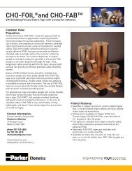
Optimizing the design of <strong>CHOFORM</strong> Shielded Housing AssembliesImportant Considerations for OptimizingQuality & Production EfficiencyA shielded housing is an assemblywhose quality and performance are functionsof all the parts and processes used toproduce it.Whenever possible, <strong>Parker</strong> Chomericsinterfaces on behalf of OEM customerswith suppliers of die-cast metal and injection-moldedplastic housings in advance oftool design and production. Detailed guidanceis provided on part and tool design,part reproducibility, locating features, tolerancesand surface conditions — issuesthat are key to the quality and economicsof robotic gasket dispensing.<strong>Parker</strong> Chomerics can act as lead vendor,managing the entire housing supplychain to ensure the best results for OEMcustomers.The following section provides answersto commonly asked questions,and highlights critical design issues thataffect production efficiency and cost.Housing Material ConsiderationsPlastic Substrate SelectionIf the housing is an injection-moldedthermoplastic, the gasket cure temperatureis an important parameter.Different thermoplastics soften orstress-relieve at different temperatures.Surface PreparationMetal or plastic surfaces to be gasketedwith <strong>CHOFORM</strong> materials shouldexhibit electrical surface resistance of
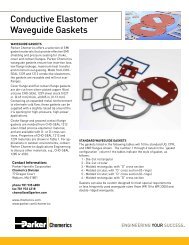
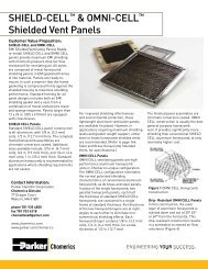
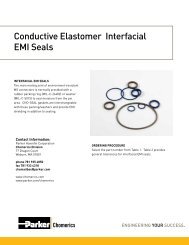
Robotically Dispensed <strong>Form</strong>-<strong>In</strong>-<strong>Place</strong> <strong>EMI</strong> <strong>Gasketing</strong>Critical Housing Design Issues<strong>CHOFORM</strong> FIP gasket technologyaccommodates a reasonable degree of variabilityin housing part dimensions. However,setup and dispensing speed are directlyimpacted by part uniformity. <strong>In</strong> addition,the housing design can pose obstacles toefficient gasket dispensing.The most common avoidable problemis warped or non-uniform housings. Ifhousings are not sufficiently flat and dimensionallyuniform, they must be restrained byspecial alignment and hold-down fixtures,which can add substantial setup time.For best results and production economics,designs should reflect the following considerations:Positive Locating FeaturesSpeed ProductionParts should be easily fixtured forfast, accurate dispensingReproducible positioning of the partsbeneath the dispensing head isfundamental to this automated technology.Maximum production speed can beachieved when through-holes are availableto pin-position parts on the pallets thattransport them to the dispensing head. Ifthrough-holes are not available, two sidescan be pushed against pallet rails for positioning.This requires hold-down clampsthat must be positioned without interferingwith the dispensing needle.Avoid features that complicatedesign of a locating systemParting lines in dies or molds can interferewith the establishment of a locatingedge. Mold gates, runners or flash caninterfere with positioning pins or fixtures.Part Reproducibility is CriticalFlanges, rails or ribs to be gasketedshould have part-to-part locationreproducibility (X and Y dimensions)within 0.008 inch (0.20 mm)Once the dispense path is programmed, allsurfaces to be gasketed must be locatedwhere the program assumes them to be.Variation greater than 0.008 inch (0.203mm) will result in gasket beads dispensedpartly on and partly off the intended surfaces.Wall heights must be reproduciblein the Z axis within 0.012 inch (0.30 mm)Manufacturing processes for die-castmetal and injection molded plastichousings generally can produce partswith intrinsically reproducible, uniformdimensions in the Z axis.Several factors determine the gasketbead profile — air pressure in the needle,material viscosity, needle diameter, feedrate and needle height (Z) above the part.Accurate Z-axis programming is centralto dispensing an optimum gasket profile.Full 3-axis programmability of the CHO-FORM dispensing heads is an importantadvantage in accommodating the necessarytolerances on the Z-axis position ofthe surface to be gasketed.Selection of a housing supplier ableto meet the reproducibility requirementsfor the Z-axis can make a real differencein the quality, speed and economics ofgasket dispensing.Production housing functions as masterThe <strong>CHOFORM</strong> gasket dispensinghead is programmed in 3 axes byplotting the path which the needle willfollow, using a representative productionhousing as the master. Programmingcan account for unintended butconsistent deviations in elevation,such as:• non-parallelism• non-flatness• warpingAs a whole, these elevation deviationsmust be consistent from part to partwithin 0.012 inch (0.30 mm).If not, special mechanical restraintfixturing will be required to ensureaccurate gasket dispensing. Fixturingschemes usually entail delay andexpense and may also impactproduction speed.Parallelism to a defined planeUsing one or more specific part featuresfor locating purposes, housings aremounted on a machined pallet and conveyedto the dispensing head. The palletsurface defines the “datum plane” forZ-axis motion of the dispensing needle.<strong>CHOFORM</strong> gaskets can be dispensedonto a part surface of known slope withrespect to the datum plane (reccomendedup to 60°). Application onto a flat surface(i.e., 0° slope) can actually be moredifficult than application to a slopedsurface if part thickness is not consistent.Variation in overall part thicknesswill cause the surface to be gasketed tobe non-parallel with the datum plane. Z-axis adjustments to the needle’s path areprogrammed using the representative“master” part. However, these variationsmust be consistent in both location anddegree, and within the 0.012 inch (0.30mm) aggregate allowable tolerance toavoid the need for special fixturing. (Figures6 a-b.)Flatness of the surface to be gasketedUnevenness in flanges, rails or ribsto be gasketed can be programmedinto the Z-axis motion of the dispensinghead. Again, this Z-axis variationmust be consistent from part-topartwithin the 0.012 inch (0.30 mm)aggregate tolerance to avoid theneed for fixturing. (Figures 7a-b.)Warping of the housingAs with parallelism and flatness of thesurface to be gasketed, warping of theentire part can contribute to a Z-axisvariation that exceeds the 0.012 inch(0.30 mm) tolerance for reproducibility.The trend toward smaller electronicpackages with thin housing walls makesthis a common occurrence. If surfacesfor part hold-down are available, thiscondition can be accommodated byfixturing. However, setup and productiontime will be affected.Optimizing the design of <strong>CHOFORM</strong> Shielded Housing Assemblies6a Non-reproducible non-parallelism >0/012 inch(0.30 mm) results in uneven bead-A-<strong>CHOFORM</strong>Material0.002Dispense Head Travel DirectionNormal ThinBead BeadFlat But Not ParallelDispensing NeedleToolCrashFigure 6 Non-parallelism between receiving surface and pallet surfaceKeep the need for part restraintto a minimumWhen the part-to-part reproducibility offlatness requirement cannot be met, mechanicalrestraints are fabricated whichtemporarily flattens the part for properdispensing of the gasket. Whenever possible,Chomerics exploits design featuressuch as through-holes and edge rails forclamping. If such features do not exist,more complicated fixturing schemesmust be designed to induce the necessaryflatness, with a corresponding timeand cost penalty.Avoid Z-axis ObstructionsSidewall proximity to the dispensingneedle Often, a form-in-place <strong>EMI</strong>gasket is applied along a “ledge” adjacentto a higher sidewall. The dimensionaltolerances on ledge and sidewalllocations are particularly critical,to avoid sidewall interference with themoving needle a minimum of 0.010”clearence is required (Figure 8).Housing0.030Carrying Fixture7a Non-reproducible non-flatness >0/012 inch(0.30 mm) results in uneven bead-A-Dispense Head Travel DirectionHigh/NarrowAreaUnevenBead<strong>CHOFORM</strong>Material0.030Carrying FixtureParallel But Not FlatLow/WideArea Dispensing NeedleHousing0.002AAFigure 7 Non-flatness of gasketed surfaceFigure 8 Sidewallinterference withdispensing needle<strong>CHOFORM</strong>Material0.002Figure 9 High sidewallsmay necessitatelonger needles, reducingspeedHigh sidewalls slow dispensingHigh sidewalls adjacent to the gasketdispensing path may require an elongatedneedle to provide the necessaryclearance for the dispensing head(Figure 9). The longer needle addsfriction to material flow, reducingdispensing speed by as much as 75%.6b Program adjusted for reproducible non-parallelism>0/012 inch(0.30 mm) results in uniform bead-A-Dispense Head Travel DirectionNormalBeadFlat But Not ParallelDispensing NeedleHousing0.030Carrying Fixture7b Program adjusted for reproducible non-flatness>0/012 inch(0.30 mm) results in uniform bead-A-<strong>CHOFORM</strong>Material0.030Carrying FixtureDispenseHead DirectionTravelParallel But Not FlatThis can frequently be avoided by positioninghigh sidewalls on the matingpart or by reducing their height to lessthan dispensed width of the gasket.Through-hole interferenceFigure 10 Dispensing path obstructed<strong>In</strong> cases where the housing incorporatesthrough-holes used to positionthe part on its pallet, the holesmust not intersect the dispensingpath. Clearance of less than 0.010inch (0.25 mm) could result in screwheads or locating pins obstructing thedispensing needle (Figure 10).ADispensing NeedleHousing-B--B--B--B-0.002A
Chomerics WorldwideNorth AmericaDivision HeadquartersWoburn, MAphone +1 781-935-4850fax +1 781-933-4318chomailbox@parker.comCranford, NJphone +1 908-272-5500fax +1 908-272-2741Millville, NJphone +1 856-825-8900Fax +1 856-825-8969Fairport, NYphone +1 585-425-7000Fax +1 585-425-7238South AmericaSao Paulo Brazilphone +55 11 4195 0444fax +55 11 4195 7580EuropeHigh Wycombe, UKphone +44 1494 455400fax +44 1494 455466chomerics_europe@parker.comGrantham, UKphone +44 1476 590600fax +44 1476 591600Saint Ouen l’Aumône, Francephone +33 1 34 32 39 00fax +33 1 34 32 58 00Asia PacificHong Kongphone +852 2428 8008fax +852 2786 3446chomerics_ap@parker.comBeijingphone +86 10 6788 4650fax +86 10 6788 4649Shanghaiphone +8621 2899 5000fax +8621 2899 5146Shenzhenphone +86 755 8974 8558fax +86 755 8974 8560Tokyo, Japanphone +81 3 6408 2369fax +81 3 5449 72022Additional facilities:Hudson, NH; Guadalajara & Monterrey, Mexico; Oulu, Finland; Sadska, Czech Republic; Tianjin, China; Chennai, <strong>In</strong>dia.www.chomerics.comwww.parker.com/chomericsCHOMERICS, ParPHorm, and <strong>CHOFORM</strong> are registered trademarks of <strong>Parker</strong> Hannifi n Corporation.© 2011-2012 <strong>Parker</strong> Hannifi n Corporation. All rights reserved.AN 1009 EN February 2014 Rev A