simpson strong-tie | liebig mechanical anchor system seismic testing ...
simpson strong-tie | liebig mechanical anchor system seismic testing ...
simpson strong-tie | liebig mechanical anchor system seismic testing ...

You also want an ePaper? Increase the reach of your titles
YUMPU automatically turns print PDFs into web optimized ePapers that Google loves.
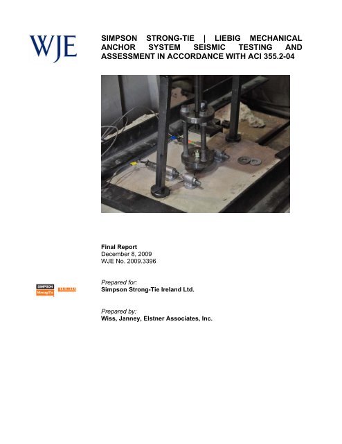
SIMPSON STRONG-TIE | LIEBIG MECHANICALANCHOR SYSTEM SEISMIC TESTING ANDASSESSMENT IN ACCORDANCE WITH ACI 355.2-04Final ReportDecember 8, 2009WJE No. 2009.3396Prepared for:Simpson Strong-Tie Ireland Ltd.Prepared by:Wiss, Janney, Elstner Associates, Inc.
SIMPSON STRONG-TIE | LIEBIG MECHANICALANCHOR SYSTEM SEISMIC TESTING ANDASSESSMENT IN ACCORDANCE WITH ACI 355.2-04John Pearson, P.E., S.E.Project ManagerFinal ReportDecember 8, 2009WJE No. 2009.3396Prepared for:Simpson Strong-Tie Ireland Ltd.German BranchWerner-von-Siemens Str. 3564319 Pfungstadt | GermanyPrepared by:Wiss, Janney, Elstner Associates, Inc.330 Pfingsten RoadNorthbrook, Illinois 60062847.272.7400 tel | 847.291.5189 fax
TABLE OF CONTENTS1.0 INTRODUCTION ..................................................................................................................................... 21.1 Purpose ................................................................................................................................................ 21.2 Scope ................................................................................................................................................... 21.3 Reference Standards ............................................................................................................................ 22.0 ANCHOR SYSTEM INFORMATION ..................................................................................................... 32.1 Product Description ............................................................................................................................. 32.2 Product Sampling ................................................................................................................................ 32.3 Concrete Test Specimens .................................................................................................................... 33.0 TEST PROGRAM ..................................................................................................................................... 33.1 Anchor Installation .............................................................................................................................. 33.2 Concrete Compressive Strength Determination .................................................................................. 43.3 Testing Methods .................................................................................................................................. 43.4 Test Equipment .................................................................................................................................... 44.0 REFERENCE AND SERVICE-CONDITION TESTS ............................................................................. 54.1 Static Tension - Test 3 Reference Tension Tests in Cracked Low Strength Concrete ........................ 54.2 Simulated Seismic Tension - Test 12 Service Condition, Simulated Seismic Tension Test ............... 55.0 TEST DATA ASSESSMENT ................................................................................................................... 66.0 CONCLUSIONS ........................................................................................................................................ 6FIGURESAPPENDIX 1APPENDIX 2APPENDIX 3Concrete Mix DesignsTest Equipment Calibration InformationSeismic Load versus Displacement Plots
SIMPSON STRONG-TIE | LIEBIG MECHANICAL ANCHOR SYSTEMSEISMIC TESTING AND ASSESSMENT INACCORDANCEWITH ACI 355.2-04December 8, 2009Page 2SIMPSON STRONG-TIE | LIEBIG MECHANICAL ANCHOR SYSTEMSEISMIC TESTING AND ASSESSMENT IN ACCORDANCEWITH ACI 355.2-041.0 INTRODUCTION1.1 PurposeThe firm of Wiss, Janney, Elstner Associates, Inc. (WJE) has conducted a product assessmentprogram for the Simpson Strong-Tie Ireland Ltd (Simpson) Superplus BLS self-undercut <strong>anchor</strong><strong>system</strong> in accordance with American Concrete Institute (ACI) 355.2-04, Qualification of Post-Installed Mechanical Anchors in Concrete and Commentary. The <strong>testing</strong> and subsequent dataassessment was conducted within the guidelines and requirements of ACI 355.2-04 for use incracked concrete. The <strong>testing</strong> took place in the WJE structural laboratory in Northbrook, Illinoisand the Simpson Strong-Tie laboratory in Addison, Illinois.1.2 ScopeThe product evaluation program consisted of <strong>testing</strong> and assessing the Simpson | Liebig Superplus BLS<strong>mechanical</strong> <strong>anchor</strong> <strong>system</strong> in cracked concrete, accoEvaluating Anchor Systems for use in Cracked and Uncracked Concrete. Specifically, Test Numbers 3and 12 of Table 4.2 were performed to determine their <strong>seismic</strong> performance.1.3 Reference StandardsACI 355.2-04, Qualification of Post-Installed Mechanical Anchors in Concrete and Commentary,American Concrete Institute, 38800 Country Club Drive, Farmington Hills, MI 48331, MichiganASTM Standard E 488-96, (Reapproved 2003): Standard Test Methods for Strength of Anchors inConcrete and Masonry Elements Vol. 04.11, ASTM International, West Conshohoken, Pennsylvania.ASTM Standard A 193/A 193M, 2006: Standard Specification for Alloy-Steel and Stainless Steel BoltingMaterials for High Temperature or High Pressure Service and Other Special Purpose Applications, Vol.01.01 , ASTM International, West Conshohoken, Pennsylvania.ASTM Standard C 31/C 31M, 2008: Standard Practice for Making and Curing Concrete TestSpecimens in the Field, Vol. 04.02, ASTM International, West Conshohoken, Pennsylvania.ASTM Standard C 39/C 39M, 2005: Standard Test Method for Compressive Strength of Cylindricalconcrete Specimens Vol. 04.02, ASTM International, West Conshohoken, Pennsylvania.
SIMPSON STRONG-TIE | LIEBIG MECHANICAL ANCHOR SYSTEMSEISMIC TESTING AND ASSESSMENT INACCORDANCE WITH ACI 355.2-04December 8, 2009Page 32.0 ANCHOR SYSTEM INFORMATION2.1 Product DescriptionThe design of the Superplus <strong>mechanical</strong> <strong>anchor</strong> causes an undercut to be created when the installationtorque is applied. As torque is applied to the <strong>anchor</strong> the cone is drawn into the <strong>anchor</strong> sleeve and thethe base material. This results in a <strong>mechanical</strong>interlock with base material that functions in both cracked and non-cracked concrete.2.2 Product SamplingProduct sampling was conducted by WJE at the Simpson facility located in Addison, Illinois. WJErandomly sampled the <strong>anchor</strong>s.2.3 Concrete Test SpecimensConcrete test specimens were typically cast as either 4 ft x 4ft x 1 ft or 6 ft x 4 ft x 2 ft blocks. A total oftwo mix designs were used during the <strong>testing</strong> process (Appendix 1). Cementitious additives as defined byACI 355.2-04 Section 5.1.2 were not used in the concrete mixes.Reinforcement was used as a necessary part of the mechanism to induce cracks in test members for testseries requiring cracked concrete. Minimum reinforcement (less than 1%) was used in static crack blocksto restrain the concrete during the cracking process. Crack inducing plates were used for each type ofcracked concrete test member to control the location of the crack in the member.3.0 TEST PROGRAM3.1 Anchor InstallationAll <strong>anchor</strong> installations were performed according toby Simpson.Drilled Holes - The holes for <strong>anchor</strong> installation were drilled using a Bosch 11241EVS SDS Max rotaryhammer drill and a carbide tipped drill bit. The diameter of the drill bits used were measured before andafter each use to verify the actual diameter was within the specified tolerance of Table 5.1 of ACI 355.2-04. All drill bits used for this test program were within the specified tolerance. The hole was drilled sothat the axis of the <strong>anchor</strong> was approximately in the plane of the crack.Anchor Installation - Anchors were installed in the concrete test members according to thedrilled using a rotary hammer drill and carbide tippeddrill bit that was within the diameter range per ACI 355.2-04, Table 5.1. The holes were drilled and the<strong>anchor</strong>s were installed to the manufacturer's recommended embedment depth.The drilled hole was cleaned using compressed air (Figure 1). A vacuum was used near the compressedair hose to collect the dust blown out of the hole and to minimize dust in the laboratory work area. The<strong>anchor</strong> was installed in the cleaned hole using a hammer. The <strong>anchor</strong> was driven until it contacted the testfixture washers indicating the desired embedment depth (Figure 2). In order to install the <strong>anchor</strong>, the nuton the threaded rod had to be hand tightened to keep all <strong>anchor</strong> components in contact with the adjacent
SIMPSON STRONG-TIE | LIEBIG MECHANICAL ANCHOR SYSTEMSEISMIC TESTING AND ASSESSMENT INACCORDANCE WITH ACI 355.2-04December 8, 2009Page 4piece. This allowed the <strong>anchor</strong> to be driven into the hole. A specified setting torque was applied to the<strong>anchor</strong> using a calibrated torque wrench. The angle of <strong>anchor</strong> installation relative to being perpendicularto the concrete surface was determined using an electronic level. Once the <strong>anchor</strong> was installed in thehole, the specified torque, T inst , was applied. The torque was removed after 10 minutes and 50 percent ofthe T inst was applied.3.2 Concrete Compressive Strength DeterminationTo determine the concrete test sample compressive strength, 6-in. x 12-in. compressive strengthspecimens were made during casting for each concrete batch in accordance with ASTM C31. The batchidentification was the date of casting with only one batch cast per day. Compressive strengthdetermination <strong>testing</strong> was then performed typically at 3, 7, 14, 21, 28, 35, 56, 91, and 180 days from thecast date according to ASTM C39. Using the compressive strength data obtained for each batch, a bestfit curve was determined using a logarithmic equation as a function of the concrete batch age at time of<strong>testing</strong> (Equation 1).Best _ fit(Age)fit Age fit fitEq. 10,0ln1,02,0When cylinders were available, the compressive strength was determined by <strong>testing</strong> two cylinders beforeand two cylinders after <strong>anchor</strong> <strong>testing</strong>. The compressive strength results were averaged to determine theconcrete compressive strength at time of <strong>testing</strong>.3.3 Testing MethodsTesting was performed by WJE personnel at the WJE Structural Laboratory in Northbrook, Illinois (TL-165) and Simpson Strong-Tie Testing facility in Addison, Illinois (TL-284) in accordance with theapplicable sections of ASTM E488 and ACI 355.2-04. The equipment used to perform the <strong>testing</strong> andrecord the values adhered to the ACI 355.2-04 criteria.3.3.1 ACI 355.2-04 Table 4.2 Test 3 - Reference Tension Tests in Cracked Low StrengthConcreteTest Number 3 is a reference tension test for single <strong>anchor</strong>s without spacing and edge effects in crackedconcrete. Results from this test series were used to calculate required load levels for Test Number 18,simulated <strong>seismic</strong> tension tests.3.3.2 ACI 355.2-04 Table 4.2 Test 12 - Service Condition, Simulated Seismic Tension TestTest Series 12 was performed for the Superplus <strong>anchor</strong>s at shallow and deep embedment. This test serieswas to determine the <strong>anchor</strong> performance during <strong>seismic</strong> tension loading in cracked (0.020-in.) concrete.Residual capacity was determined after successful completion of the <strong>seismic</strong> tension <strong>testing</strong>.3.4 Test EquipmentAll <strong>testing</strong> was performed in accordance to the requirements of ACI 355.2-04 and ASTM E488. Statictension tests were performed using a hollow core hydraulic ram, hydraulic pump, load cell, linear variablecontrolled data acquisition <strong>system</strong> (Figure 3).
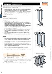
SIMPSON STRONG-TIE | LIEBIG MECHANICAL ANCHOR SYSTEMSEISMIC TESTING AND ASSESSMENT INACCORDANCE WITH ACI 355.2-04December 8, 2009Page 5Seismic tension tests were performed using a computer controlled closed-loop hydraulic actuator. A loadcell is connected in-line with the actuator (Figure 4). An LVDT is mounted to the actuator fordisplacement measurements. Data was collected by the computer.The calibration information for equipment used for installing and <strong>testing</strong> the Superplus <strong>anchor</strong>s isincluded in Appendix 2.4.0 REFERENCE AND SERVICE-CONDITION TESTSThe reference tests were performed to obtain baseline values for the service-condition tests.4.1 Static Tension - Test 3 Reference Tension Tests in Cracked Low StrengthConcreteAnchor Installation - A hairline crack was developed in the concrete test member using hydraulics(Figure 5). The hole was drilled as previously described. The hole was cleaned with compressed air. Aborescope was used to verify that the axis of the <strong>anchor</strong> would be within the plane of the crack. The<strong>anchor</strong> was then installed and set as previously described.Anchors were installed in concrete following the manuwas installed in the hole the specified torque, T inst , was applied. The torque was removed after 10 minutesand 50 percent of T inst was applied.Static Testingack width. Each LVDT was secured to theconcrete surface approximately equal distant on either side of the <strong>anchor</strong>. Once the <strong>anchor</strong> was set, thecrack width was increased to 0.012-in in addition to the initial hairline width as required by ACI 355.2,Section 5.2.3. The LVDT readings were averaged and the result was reported as the crack width for thetest. Once the <strong>testing</strong> was begun the crack width was not controlled.An initial load of approximately 5 percent of the expected ultimate capacity was applied to the <strong>anchor</strong> inaccordance with ASTM E488, Section 8.5. The load was applied continuously using an electric hydraulicpump. The load rate was maintained so that failure occurred between 1 and 3 minutes from the beginningof continuous load application in accordance with ASTM E488. An LVDT was used to measure the<strong>anchor</strong> displacement during loading. A computer controlled data acquisition <strong>system</strong> was used tocontinuously collect the load - displacement data, which was plotted in real time.4.2 Simulated Seismic Tension - Test 12 Service Condition, Simulated SeismicTension TestAnchor installation, concrete test member cracking, <strong>anchor</strong> <strong>testing</strong>, and data collection was performed asthe crack width. Each LVDT was secured to theconcrete surface approximately equal distant on either side of the <strong>anchor</strong>. Once the <strong>anchor</strong> was set, thecrack width was increased from the initial hairline crack width to the specified amount using wedges asrequired by ACI 355.2, Section 5.2.3. The crack width opening at the beginning of all tests was 0.020 in.The LVDT readings were averaged and the result was reported as the crack width for the test. Once the<strong>testing</strong> was begun the crack width was not controlled.The <strong>anchor</strong>s were subjected to multiple cycles of pulsating tension loads at a frequency of 0.2 Hz. Themaximum <strong>seismic</strong> tension test load, N eq , for each <strong>anchor</strong> was based on the results of the static tension<strong>testing</strong> (reference tension tests) as described above for each diameter and embedment depth condition.
SIMPSON STRONG-TIE | LIEBIG MECHANICAL ANCHOR SYSTEMSEISMIC TESTING AND ASSESSMENT INACCORDANCE WITH ACI 355.2-04December 8, 2009Page 6The value of the three tension loads (N eq , N m , N i ,) is listed below. The number of cycles performed at loadlevels N eq , N m , and N i , were 10, 30, and 100, respectively.SuperplusDiameter (mm)Embedment (mm) N eq (kN) N i (kN) N m (kN)12 80 22.1 16.6 11.112 150 37.9 28.4 18.916 150 43.0 32.2 21.516 200 61.1 45.8 30.5A plot of applied <strong>seismic</strong> load versus <strong>anchor</strong> displacement for each test is included in Appendix 3. At thecompletion of the simulated <strong>seismic</strong> tests a residual capacity test was performed. The same test set up forthe <strong>seismic</strong> tests was used for the residual capacity tests. The crack width at the end of the simulated<strong>seismic</strong> tests was the crack width for the residual capacity tests, but not less than 0.020-in.5.0 TEST DATA ASSESSMENTThe mean residual capacity for all <strong>anchor</strong>s of Test Series 12 exceeded 160 percent of the maximumsinusoidal tension, N eq (80 percent of the Reference Test 3 average). The <strong>anchor</strong>s meet the criteria forTest Series 18. Below is a summary of the mean residual capacity and corresponding limiting values.Anchor DiameterTest Series 12Embedment (mm)(mm)Residual Capacity (kN) 160% Neq (kN)12 80 40.7 35.412 150 74.5 60.616 150 75.2 68.816 200 135.9 97.76.0 CONCLUSIONSThe <strong>testing</strong> program was conducted in general conformance with the requirements of ACI 355.2-04.Simulated <strong>seismic</strong> tension loading was performed on each <strong>anchor</strong> and residual tension tests wereperformed after completion of the simulated <strong>seismic</strong> loading. For each diameter and embedment depthcondition tested, the average ultimate residual loads of Test Series 12 exceeded 160 percent of themaximum tension load applied during the simulated <strong>seismic</strong> tension tests, N eq (80 percent of the averageultimate Test Series 3 reference tension loads). Therefore, the Simpson Strong-Tie Superplus BLS selfundercutting<strong>anchor</strong> meets the <strong>seismic</strong> tension resistance requirements of ACI 355.2-04 Section 9.5.3 withno performance reduction.
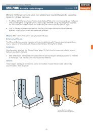
SIMPSON STRONG-TIE | LIEBIG MECHANICAL ANCHOR SYSTEMSEISMIC TESTING AND ASSESSMENT INACCORDANCE WITH ACI 355.2-04December 8, 2009Page 7VacuumhoseCompressed airhoseFigure 1. Hole cleaning with compressed air
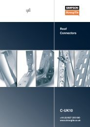
SIMPSON STRONG-TIE | LIEBIG MECHANICAL ANCHOR SYSTEMSEISMIC TESTING AND ASSESSMENT INACCORDANCE WITH ACI 355.2-04December 8, 2009Page 8Figure 2. Anchor installationLoad cellHydraulicramLVDTFigure 3. Static tension test set up in cracked concrete.
Figure 4. Seismic tension test set up.SIMPSON STRONG-TIE | LIEBIG MECHANICAL ANCHOR SYSTEMSEISMIC TESTING AND ASSESSMENT INACCORDANCE WITH ACI 355.2-04December 8, 2009Page 9
SIMPSON STRONG-TIE | LIEBIG MECHANICAL ANCHOR SYSTEMSEISMIC TESTING AND ASSESSMENT INACCORDANCE WITH ACI 355.2-04December 8, 2009Page 10ReinforcingsteelFigure 5. Hydraulics used to initiate crack.