simpson strong-tie | liebig mechanical anchor system seismic testing ...
simpson strong-tie | liebig mechanical anchor system seismic testing ...
simpson strong-tie | liebig mechanical anchor system seismic testing ...

Create successful ePaper yourself
Turn your PDF publications into a flip-book with our unique Google optimized e-Paper software.
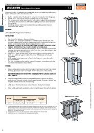
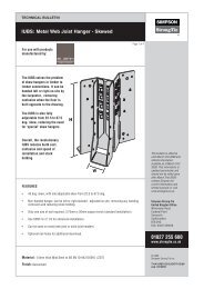
SIMPSON STRONG-TIE | LIEBIG MECHANICAL ANCHOR SYSTEMSEISMIC TESTING AND ASSESSMENT INACCORDANCE WITH ACI 355.2-04December 8, 2009Page 32.0 ANCHOR SYSTEM INFORMATION2.1 Product DescriptionThe design of the Superplus <strong>mechanical</strong> <strong>anchor</strong> causes an undercut to be created when the installationtorque is applied. As torque is applied to the <strong>anchor</strong> the cone is drawn into the <strong>anchor</strong> sleeve and thethe base material. This results in a <strong>mechanical</strong>interlock with base material that functions in both cracked and non-cracked concrete.2.2 Product SamplingProduct sampling was conducted by WJE at the Simpson facility located in Addison, Illinois. WJErandomly sampled the <strong>anchor</strong>s.2.3 Concrete Test SpecimensConcrete test specimens were typically cast as either 4 ft x 4ft x 1 ft or 6 ft x 4 ft x 2 ft blocks. A total oftwo mix designs were used during the <strong>testing</strong> process (Appendix 1). Cementitious additives as defined byACI 355.2-04 Section 5.1.2 were not used in the concrete mixes.Reinforcement was used as a necessary part of the mechanism to induce cracks in test members for testseries requiring cracked concrete. Minimum reinforcement (less than 1%) was used in static crack blocksto restrain the concrete during the cracking process. Crack inducing plates were used for each type ofcracked concrete test member to control the location of the crack in the member.3.0 TEST PROGRAM3.1 Anchor InstallationAll <strong>anchor</strong> installations were performed according toby Simpson.Drilled Holes - The holes for <strong>anchor</strong> installation were drilled using a Bosch 11241EVS SDS Max rotaryhammer drill and a carbide tipped drill bit. The diameter of the drill bits used were measured before andafter each use to verify the actual diameter was within the specified tolerance of Table 5.1 of ACI 355.2-04. All drill bits used for this test program were within the specified tolerance. The hole was drilled sothat the axis of the <strong>anchor</strong> was approximately in the plane of the crack.Anchor Installation - Anchors were installed in the concrete test members according to thedrilled using a rotary hammer drill and carbide tippeddrill bit that was within the diameter range per ACI 355.2-04, Table 5.1. The holes were drilled and the<strong>anchor</strong>s were installed to the manufacturer's recommended embedment depth.The drilled hole was cleaned using compressed air (Figure 1). A vacuum was used near the compressedair hose to collect the dust blown out of the hole and to minimize dust in the laboratory work area. The<strong>anchor</strong> was installed in the cleaned hole using a hammer. The <strong>anchor</strong> was driven until it contacted the testfixture washers indicating the desired embedment depth (Figure 2). In order to install the <strong>anchor</strong>, the nuton the threaded rod had to be hand tightened to keep all <strong>anchor</strong> components in contact with the adjacent