
Create successful ePaper yourself
Turn your PDF publications into a flip-book with our unique Google optimized e-Paper software.
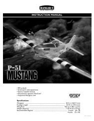
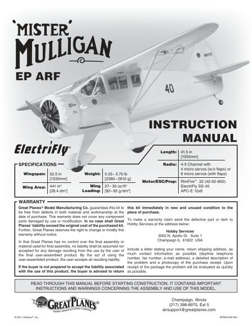
EP ARFINSTRUCTIONMANUAL®Length:41.5 in[1055mm]SPECIFICATIONSWingspan:52.5 in[1335mm]Wing Area: 441 in 2[28.4 dm 2 ]Weight:WingLoading:5.25– 5.75 lb[2380– 2610 g]27– 30 oz/ft 2[82– 92 g/dm 2 ]Radio:4-5 Channel with4 micro servos (w/o flaps) or6 micro servos (with flaps)Motor/ESC/Prop: RimFire .32 (42-50-800)ElectriFly SS-45APC-E 12x8WARRANTYGreat Planes ® Model Manufacturing Co. guarantees this kit tobe free from defects in both material and workmanship at thedate of purchase. This warranty does not cover any componentparts damaged by use or modification. In no case shall GreatPlanes’ liability exceed the original cost of the purchased kit.Further, Great Planes reserves the right to change or modify thiswarranty without notice.In that Great Planes has no control over the final assembly ormaterial used for final assembly, no liability shall be assumed noraccepted for any damage resulting from the use by the user ofthe final user-assembled product. By the act of using theuser-assembled product, the user accepts all resulting liability.If the buyer is not prepared to accept the liability associatedwith the use of this product, the buyer is advised to returnthis kit immediately in new and unused condition to theplace of purchase.To make a warranty claim send the defective part or item toHobby Services at the address below:Hobby Services3002 N. Apollo Dr. Suite 1Champaign IL 61822 USAInclude a letter stating your name, return shipping address, asmuch contact information as possible (daytime telephonenumber, fax number, e-mail address), a detailed description ofthe problem and a photocopy of the purchase receipt. Uponreceipt of the package the problem will be evaluated as quicklyas possible.READ THROUGH THIS MANUAL BEFORE STARTING CONSTRUCTION. IT CONTAINS IMPORTANTINSTRUCTIONS AND WARNINGS CONCERNING THE ASSEMBLY AND USE OF THIS MODEL.Champaign, Illinois(217) 398-8970, Ext 5airsupport@greatplanes.com© 2011 <strong>Hobbico</strong> ® , Inc. GPMA1485 Mnl
TABLE OF CONTENTSINTRODUCTION . . . . . . . . . . . . . . . . . . . . . . . . . . . . . . . .2AMA . . . . . . . . . . . . . . . . . . . . . . . . . . . . . . . . . . . . . . . . . .2SAFETY PRECAUTIONS . . . . . . . . . . . . . . . . . . . . . . . . .2ITEMS REQUIRED. . . . . . . . . . . . . . . . . . . . . . . . . . . . . . .3Radio Equipment . . . . . . . . . . . . . . . . . . . . . . . . . . . . .3Motor, ESC, & Propeller Recommendations . . . . . . . .3Battery & Charger Recommendations . . . . . . . . . . . . .3Required Adhesive & Building Supplies. . . . . . . . . . . .4Optional Supplies & Tools . . . . . . . . . . . . . . . . . . . . . .4IMPORTANT BUILDING NOTES. . . . . . . . . . . . . . . . . . . .4KIT INSPECTION. . . . . . . . . . . . . . . . . . . . . . . . . . . . . . . .4ORDERING REPLACEMENT PARTS . . . . . . . . . . . . . . . .5KIT CONTENTS. . . . . . . . . . . . . . . . . . . . . . . . . . . . . . . . .5BEFORE YOU BEGIN . . . . . . . . . . . . . . . . . . . . . . . . . . . .6WING ASSEMBLY . . . . . . . . . . . . . . . . . . . . . . . . . . . . . . .6Aileron Servo Installation . . . . . . . . . . . . . . . . . . . . . . .6Fixed Flap Option 1 . . . . . . . . . . . . . . . . . . . . . . . . . . .8Fixed Flap Option 2 . . . . . . . . . . . . . . . . . . . . . . . . . . .9Servo Operated Flap Option 3 . . . . . . . . . . . . . . . . . .11FUSELAGE ASSEMBLY . . . . . . . . . . . . . . . . . . . . . . . . .13Main Landing Gear Installation . . . . . . . . . . . . . . . . .13Tail Installation . . . . . . . . . . . . . . . . . . . . . . . . . . . . . .14Tailwheel & Rudder Installation . . . . . . . . . . . . . . . . .15Servo Installation . . . . . . . . . . . . . . . . . . . . . . . . . . . .16MOTOR, ESC & RADIO INSTALLATION . . . . . . . . . . . .18COWL & PROPELLER INSTALLATION . . . . . . . . . . . . .20FINAL ASSEMBLY . . . . . . . . . . . . . . . . . . . . . . . . . . . . .22Pilot Installation (Optional) . . . . . . . . . . . . . . . . . . . . .23Apply the Decals . . . . . . . . . . . . . . . . . . . . . . . . . . . .23GET THE MODEL READY TO FLY . . . . . . . . . . . . . . . . .23Center the Controls & Check the Control Directions .23Set the Control Throws. . . . . . . . . . . . . . . . . . . . . . . .24Balance the Model (C.G.). . . . . . . . . . . . . . . . . . . . . .25Balance the Model Laterally. . . . . . . . . . . . . . . . . . . .25PREFLIGHT . . . . . . . . . . . . . . . . . . . . . . . . . . . . . . . . . . .26Identify Your Model. . . . . . . . . . . . . . . . . . . . . . . . . . .26Balance Propellers. . . . . . . . . . . . . . . . . . . . . . . . . . .26Range Check . . . . . . . . . . . . . . . . . . . . . . . . . . . . . . .26MOTOR SAFETY PRECAUTIONS . . . . . . . . . . . . . . . . .26AMA SAFETY CODE. . . . . . . . . . . . . . . . . . . . . . . . . . . .26CHECKLIST. . . . . . . . . . . . . . . . . . . . . . . . . . . . . . . . . . .27FLYING. . . . . . . . . . . . . . . . . . . . . . . . . . . . . . . . . . . . . . .27Takeoff . . . . . . . . . . . . . . . . . . . . . . . . . . . . . . . . . . . .27Flight . . . . . . . . . . . . . . . . . . . . . . . . . . . . . . . . . . . . .28Landing . . . . . . . . . . . . . . . . . . . . . . . . . . . . . . . . . . .28AMAAcademy of Model Aeronautics:If you are not already amember of the AMA, please join! The AMA is the governingbody of model aviation and membership provides liabilityinsurance coverage, protects modelers’ rights and interestsand is required to fly at most R/C sites.Academy of ModelAeronautics5151 East Memorial DriveMuncie, IN 47302-9252Tele. (800) 435-9262Fax (765) 741-0057www.modelaircraft.orgIMPORTANT!!!Two of the most important things you can do to preserve theradio controlled aircraft hobby are to avoid flying near fullscaleaircraft and avoid flying near or over groups of people.SCALE COMPETITIONThough the Great Planes Mister Mulligan EP is an ARF andmay not have the same level of detail as an “all-out” scratchbuiltcompetition model, it is a scale model nonethelessand is therefore eligible to compete in the Fun Scale classin AMA competition (we receive many favorable reports ofGreat Planes ARF’s in scale competition!). In Fun Scale, the“builder of the model” rule does not apply. To receive the fivepoints for scale documentation, the only proof required that afull size aircraft of this type in this paint/markings scheme didexist is a single sheet such as a kit box cover from a plasticmodel, a photo, or a profile painting, etc. If the photo is inblack and white other written documentation of color mustbe provided. Contact the AMA for a rule book with full details.If you would like photos of the full-size Mister Mulligan forscale documentation, or if you would like to study the photosto add more scale details, photo packs are available from:Bob’s Aircraft Documentation3114 Yukon AveCosta Mesa, CA 92626Phone: (714) 979-8058Fax: (714) 979-7279www.bobsairdoc.comPROTECT YOUR MODEL, YOURSELF& OTHERS… FOLLOW THESEIMPORTANT SAFETY PRECAUTIONSINTRODUCTIONFor the latest technical updates or manual corrections to theMister Mulligan EP visit the Great Planes web site at www.greatplanes.com. Open the “Airplanes” link, then select theMister Mulligan EP ARF. If there is new technical informationor changes to this model a “tech notice” box will appear inthe upper left corner of the page.21. Your Mister Mulligan EP should not be considered a toy,but rather a sophisticated, working model that functions verymuch like a full-size airplane. Because of its performancecapabilities, the Mister Mulligan EP, if not assembled andoperated correctly, could possibly cause injury to yourself orspectators and damage to property.2. You must assemble the model according to the instructions.Do not alter or modify the model, as doing so may result in anunsafe or unflyable model. In a few cases the instructions may
differ slightly from the photos. In those instances the writteninstructions should be considered as correct.3. You must take time to build straight, true and strong.4. You must use an R/C radio system that is in good condition,a correctly sized engine, and other components as specifiedin this instruction manual. All components must be correctlyinstalled so that the model operates correctly on the groundand in the air. You must check the operation of the model andall components before every flight.5. If you are not an experienced pilot or have not flownthis type of model before, we recommend that you get theassistance of an experienced pilot in your R/C club foryour first flights. If you’re not a member of a club, your localhobby shop has information about clubs in your area whosemembership includes experienced pilots.6. While this kit has been flight tested to exceed normal use,if the plane will be used for extremely high stress flying, suchas racing, or if a motor larger than one in the recommendedrange is used, the modeler is responsible for taking steps toreinforce the high stress points and/or substituting hardwaremore suitable for the increased stress.7. WARNING: The cowl, wheel pants, and some fairings aremade of fiberglass, the fibers of which may cause eye, skinand respiratory tract irritation. Never blow into or on a partto remove fiberglass dust, as the dust will blow back intoyour eyes. Always wear safety goggles, a particle mask andrubber gloves when grinding, drilling and sanding fiberglassparts. Vacuum the parts and the work area thoroughly afterworking with fiberglass parts.We, as the kit manufacturer, provide you with a top quality,thoroughly tested kit and instructions, but ultimately thequality and fl yability of your fi nished model dependson how you build it; therefore, we cannot in any wayguarantee the performance of your completed model,and no representations are expressed or implied as to theperformance or safety of your completed model.Remember: Take your time and follow the instructions toend up with a well-built model that is straight and true.ITEMS REQUIREDRadio EquipmentA 4-channel minimum radio system is required to fly thismodel. We recommend using a 6-channel radio so that wingflaps can be used.❏ Futaba ® R617FS 7-channel 2.4GHz ReceiverOR❏ Futaba R114F FM Micro Receiver(Low Band – FUTL0442, High Band – FUTL0443)❏ Futaba FM Single Conversion Short Crystal(Low Band – FUTL62**, High Band – FUTL63**)No Flaps Option❏ (1) Y-harness (FUTM4130)❏ (4) Futaba 3115 Micro Precision Servo (FUTM0415)OR❏ (4) minimum 39 oz-in (2.8 kg-cm) Micro ServosOperable Flaps Option❏ (2) Y-harness (FUTM4130)❏ (2) 6" [150mm] servo extension (HCAM2701 for Futaba)❏ (6) Futaba 3115 Micro Precision Servo (FUTM0415)OR❏ (6) minimum 39 oz-in (2.8 kg-cm) Micro ServosMotor, ESC and Propeller❏ Great Planes RimFire .32 (42-50-800kV) BrushlessOutrunner Motor (GPMG4700)❏ Great Planes Silver Series 45A Brushless ESC(GPMM1840)❏ APC 12x8 Electric Propeller (APCQ4133)Battery and ChargerOther battery packs will also work in this model, but pleasebe sure to always use a 4S LiPo pack that can supply at least45A continuous.❏ FlightPower ® EON-X 4350mAh 14.8V 30C LiPo(FPWP6576)❏ Great Planes ElectriFly Triton EQ AC/DC Charger(GPMM3155)LIPO WARNING!!Read the entire instruction sheet included with the battery.Failure to follow all instructions could cause permanentdamage to the battery and its surroundings, and causebodily harm!• ONLY use a LiPo approved charger.• NEVER charge in excess of 4.20V per cell.• ONLY charge through the “charge” lead. NEVER chargethrough the “discharge” lead.• NEVER charge at currents greater than 1C.• ALWAYS set charger’s output volts to match batteryvolts.• ALWAYS charge in a fi reproof location.• NEVER trickle charge.• NEVER allow battery temperature to exceed 150° F (65° C).• NEVER disassemble or modify pack wiring in any wayor puncture cells.• NEVER discharge below 3.0V per cell• NEVER place on combustible materials or leaveunattended during charge or discharge.• ALWAYS KEEP OUT OF REACH OF CHILDREN.❏ (2) 12" [300mm] servo extension(HCAM2711 for Futaba)3
Required Adhesivesand Building SuppliesTo finish this airplane you will need the following items.❏ 1 oz. [30g] Thin Pro CA (GPMR6002)❏ 1 oz. [30g] Medium Pro CA+ (GPMR6008)❏ 2 oz. [60g] Foam Safe CA Activator (GPMR6035)❏ Pro 6-minute epoxy (GPMR6045)❏ R/C-56 canopy glue 4oz (JOZR5007)❏ #11 Hobby knife w/ 5 blades (EXLR9018)❏ 3/32" Long Ball-Driver (GPMR8002)❏ Drill bits: 1/16" [1.6mm], 5/64" [2mm], 3/32" [2.4mm]❏ Builder’s Triangle Set (HCAR0480)❏ 18" flexible steel rule (HCAR0460)❏ <strong>Hobbico</strong> Heavy Duty Diagonal Cutter 7" (HCAR0627)❏ Pliers with wire cutter (HCAR0625)❏ Panel Line Pen (TOPQ2510)❏ Medium T-pins (100, HCAR5150)❏ Epoxy brushes (6, GPMR8060)❏ Mixing sticks (50, GPMR8055)❏ Mixing cups (GPMR8056)❏ Threadlocker thread locking cement (GPMR6060)❏ Denatured alcohol (for epoxy clean up)❏ Light machine oil❏ Flat metal file❏ Masking tapeOptional Supplies and Tools❏ Pro 30-minute epoxy (GPMR6047)❏ 3/8" [9.5mm] heat-shrink tubing (DUBM2180)❏ 21st Century ® sealing iron (COVR2700)❏ 21st Century iron cover (COVR2702)❏ Rotary tool such as Dremel ®❏ Rotary tool reinforced cut-off wheel (GPMR8200)❏ CA applicator tips (HCAR3780)❏ CA debonder (GPMR6039)❏ Dremel Drum Sander, Coarse 3/8” (DRER0968)❏ Great Planes Easy-Touch Hand Sander 5.5”(GPMR6169)❏ Great Planes Easy-Touch Sandpaper 150 Grit(GPMR6183)❏ Great Planes 1/5th Scale Sport Pilot – Red(GPMQ9015)❏ Great Planes 1/5th Scale Sport Pilot – Blue(GPMQ9016)❏ Great Planes 1/5th Scale Sport Pilot – Yellow(GPMQ9017)❏ Revell ® Razor Saw (RMXR6960)IMPORTANT BUILDING NOTES• There are three types of screws used in this kit:Sheet metal screws are designated bya number and a length. For example,#6 x 3/4" [19mm]Machine screws are designated by anumber, threads per inch, and a length.For example 4-40 x 3/4" [19mm]Socket Head Cap Screws (SHCS) aredesignated by a number, threads perinch, and a length. For example 4-40 x3/4" [19mm]• When you see the term test fit in the instructions, it meansthat you should first position the part on the assemblywithout using any glue, and then slightly modify or customfit the part as necessary for the best fit.• Whenever the term glue is written you should rely uponyour experience to decide what type of glue to use. Whena specific type of adhesive works best for that step, theinstructions will make a recommendation.• Whenever just epoxy is specified you may use either30-minute (or 45-minute) epoxy or 6-minute epoxy. When30-minute epoxy is specified it is highly recommended thatyou use only 30-minute (or 45-minute) epoxy, because youwill need the working time and/or the additional strength.• Photos and sketches are placed before the step theyrefer to. Frequently you can study photos in following stepsto get another view of the same parts.• The Mister Mulligan EP is factory-covered with Jet WhiteTop Flite ® MonoKote ® film (TOPQ0204). Should repairsever be required, MonoKote can be patched with additionalMonoKote purchased separately. MonoKote is packaged insix-foot rolls, but some hobby shops also sell it by the foot. Ifonly a small piece of MonoKote is needed for a minor patch,perhaps a fellow modeler would give you some. MonoKoteis applied with a model airplane covering iron, but in anemergency a regular iron could be used. A roll of MonoKoteincludes full instructions for application.4
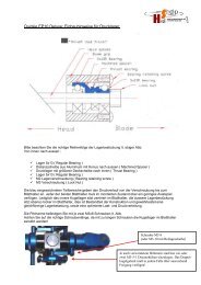
GPMA1485 D01 ©2010 Great PlanesKIT INSPECTIONBefore starting to build, take an inventory of this kit to makesure it is complete, and inspect the parts to make sure theyare of acceptable quality. If any parts are missing or are not ofacceptable quality, or if you need assistance with assembly,contact Product Support. When reporting defective ormissing parts, use the part names exactly as they are writtenin the Kit Contents list.Great Planes Product Support:3002 N Apollo Drive, Suite 1Champaign, IL 61822Telephone: (217) 398-8970, ext. 5Fax: (217) 398-7721E-mail: airsupport@greatplanes.comORDERING REPLACEMENT PARTSReplacement parts for the Mister Mulligan EP are availableusing the order numbers shown below. The fastest, mosteconomical service can be provided by your hobby dealer ormail-order company.To locate a hobby dealer, visit the Great Planes web siteat www.greatplanes.com. Choose “Where to Buy” at thebottom of the menu on the left side of the page. Follow theinstructions provided on the page to locate a U.S., Canadianor International dealer.Parts may also be ordered directly from Hobby Servicesby calling (217) 398-0007, or fax at (217) 398-7721, but fullretail prices and shipping and handling charges will apply.Illinois and Nevada residents will also be charged sales tax.If ordering via fax, include a Visa ® or MasterCard ® numberand expiration date for payment.Mail parts orders and payments by personal check to:Hobby Services3002 N. Apollo Drive, Suite 1Champaign, IL 61822Be certain to specify the order number exactly as listed inthe Replacement Parts List. Payment by credit card orpersonal check only; no C.O.D.If additional assistance is required for any reason, contactProduct Support by telephone at (217) 398-8970, or bye-mail at productsupport@greatplanes.com.KIT CONTENTSHatchVerticalStabilizerGPMA4123FuselageGPMA4126DummyEngineCowlGPMA4120HorizontalStabilizerGPMA4122GPMA4124Cowl & Dummy EngineGPMA4125Dummy Engine OnlyWing HalvesLandingGearWing TubeGPMA4131GPMA4121GPMA4127Wing StrutsWheelPantsGPMA4129GPMA4130GPMA4128NOTEFull-size plans are not available. You can download a copy of this manual at greatplanes.com.5
BEFORE YOU BEGINBefore you begin assembling your model, inspect it forwrinkled covering and areas where the covering should betacked down to the wood like the openings for the servobays. Use Low heat (about 250° F [121° C]) to tack down theedges. Raise the temperature and iron over wrinkles withlight pressure. Be careful not to contact the edges that youtacked down while shrinking.❏ ❏ 2. Working with the left wing, remove the aileron servobay cover. Center the servo arm in the opening with the armpointing out as shown. With the servo in this position, gluetwo 7mm x 10mm x 14mm hardwood blocks under the servomounting tabs. If you are using the recommended FutabaS3115 servos, you may simply use epoxy to glue the blocksin the positions marked inside the cover.Note: Save the plastic bag that the fuselage came in. It willbe used later in the assembly.WING ASSEMBLYAileron Servo Installation❏ ❏ 3. Drill mounting holes for the servo using a 1/16"[1.6mm] drill. Install the two servo screws that came with yourservo. Remove the screws and the servo and wick a drop ofthin CA into the screw threads that you just tapped in thehardwood blocks. After the CA cures, re-install the screws.❏ 1. Prepare a left and a right servo using your radio systemto center the servos. Remove the servo arm retaining screwsand the servo arms. Install the standard size servo arms thatcame with your servos. Rotate the arm on the splined servoshaft and choose the arm that is 90° to the side of the servocase when the servo is centered. Clip off the unused servoarms so that your aileron servos appear as shown. Fit anyservo grommets now (if equipped).6❏ ❏ 4. Attach a 12" [305mm] servo lead extension to theaileron servo. Secure the connection with a piece of 3/8"[9.5mm] diameter heat shrink tubing (not supplied) or wrapthe connection with electrical tape.
❏ ❏ 5. Tie the guide string to the end of the servo lead andcarefully route the servo lead through the wing and out of thehole in the sheeting near the root rib of the wing.❏ ❏ 8. Clip off and discard the backing plate from a smallcontrol horn. Align the horn over the mark you made andslide it forward until the pushrod holes in the horn are directlyover the hinge line. Drill two 3/8" [9.5mm] deep holes using a1/16" [1.6mm] drill. Be careful not to drill completely throughthe aileron.❏ ❏ 9. Install the control horn using two #2 x 3/8" [9.5mm]sheetmetal screws. Remove the screws and the horn andwick about 4-5 drops of thin CA into the screw holes youtapped. Allow the CA to dry and reinstall the control horn.❏ ❏ 6. Orient the servo bay cover as shown and install itusing four #2 x 3/8" [9.5mm] sheetmetal screws with four#2 flat washers. Remove the screws, washers and the coverand harden the screw holes in the wing with thin CA. Then,re-install the cover and screws.❏ ❏ 10. Screw a clevis onto a 6" [152mm] threaded pushrodso that at least 1/8" [3.2mm] of thread protrudes past thebarrel of the clevis. Loosely fit a silicone clevis retainer to thepushrod.❏ ❏ 7. Using a 90° builder’s square or a builder’s triangle,make a mark on the aileron directly behind the aileron servoarm. Align the flat base of the square with the aileron hingeline. Then slide the square into position and make your mark.7❏ ❏ 11. Fit the clevis to the outermost hole in the aileroncontrol horn. Extend the pushrod forward and align it withthe hole you drilled in the servo arm. With the servo armcentered and the aileron at neutral, make a mark at the holein the servo arm.
❏ ❏ 12. Bend the pushrod 90° at the mark that you made.Fit the pushrod to the servo arm and fasten it with a FasLinkpushrod retainer. Cut off the remaining pushrod so that atleast 1/4" [6.4mm] of pushrod remains.❏ 13. Repeat steps 2 through 12 to prepare the right wing.❏ 16. Glue the 3mm x 20mm wing alignment dowel into theleft wing as shown so that at least 10mm is protruding.Fixed Wing Flap (Option 1)On this model, you can set up the flaps one of three ways.You can purchase two additional servos and use flaps forlandings. If you never intend to use flaps, you may glue theflaps in the fully retracted position. If you want the option toadd flaps later you can install the control horns and fix themin place using the supplied flap pushrod.❏ 14. Glue a 6mm x 25mm wing dowel into the leading edgeof each wing so that the dowel protrudes out 1/4" [6.4mm]as shown.❏ 1. To permanently fix the flaps in the retracted position,glue the wing flap servo bay covers in place.❏ 15. Sand the surface of the wing alignment dowel toprepare it for glue.8❏ 2. Trim the covering from the leading edge of each flap.Remove the covering from the trailing edge of the wing infront of each flap. Trim the covering about 1/16" [1.6mm]inside of the edge.
6-minute epoxy, you can heat up the glue joint later andeasily remove the fixed flap retainers to convert to operableflaps.❏ 3. Mix up a batch of 6-minute epoxy. Brush epoxy on theleading edge of each flap and the corresponding trailingedge of each wing. Glue each flap in the retracted position.Before the epoxy cures, wipe off the excess with a papertowel dampened with denatured alcohol.Fixed Wing Flap (Option 2)With this option, you can easily add operable flaps later.❏ 3. Trim away the covering from the three small holes.Install a nylon strap across the two longitudinal holes usingtwo of the sheetmetal screws included with the straps. Don’tforget to harden the screw holes with thin CA. Prepare bothservo bay covers.❏ 1. Identify the four wooden fixed flap retainers shownhere. Rotate the small oval piece until the three holes in thatpiece align with the three holes in the larger piece. Glue thesmall oval piece to the larger piece. Use the laser-etchedoutline and the holes to center the small oval piece. Allow theglue to dry. Note: The pair that you create will not be mirrorimages because both flap servo arms must operate in thesame direction as they exit the wing.❏ 4. Install the covers onto the wings. Be careful to orientthe covers properly as shown.❏ 2. Glue the pieces into the flap servo bay covers using6-minute epoxy. Do not remove the covering. By using9
❏ ❏ 5. Working with the left wing first, make a mark on theflap LE directly behind the side opposite the hole in eachservo bay cover. This is the side the pushrod will be on.❏ ❏ 10. Bend the pushrod 90°. Insert the bent portionunder the hump of the nylon strap. Make a mark at the pointyou will make the second 90° bend.❏ ❏ 6. Hold a small control horn over the mark you madewith the pushrod holes directly over the hinge line. Drill two3/8" [9.5mm] deep holes using a 1/16" [1.6mm] drill bit.❏ ❏ 7. Install the control horn using two #2 x 3/8" [9.5mm]sheetmetal screws.❏ ❏ 8. Prepare a 6" [152mm] pushrod the same way youprepared the aileron servos using one nylon clevis and asilicone clevis retainer.❏ ❏ 11. Remove the pushrod and make the second 90°bend so that it is vertical as shown.❏ ❏ 9. Attach the clevis to the outermost hole in the flapcontrol horn. Extend the pushrod forward and mark the pointthat you will make the first 90° bend.10❏ ❏ 12. Remove the nylon strap and reinstall the pushrod.Make any adjustments to the length of the pushrod bytightening or loosening the clevis until the flap is set in theretracted position.
❏ 13. Repeat steps 5 through 12 to finish the right wing.Remember to orient the servo bay cover properly. Use thephoto above for reference.❏ 14. To add operable flaps later, remove the pushrod fromthe servo bay cover. Using a heat gun, heat up the woodenflap retainer pieces you glued in place until you soften theepoxy. Use a flat razor blade to separate the glue joint andremove the retainer pieces from the servo bay covers. Followthe directions in the next section to install and set up flapservos. Note: Clip off the last 90° bend from the pushrodsand reuse them to hook up your servos.❏ ❏ 2. Establish the rotation direction of your flap servos.Lay one flap servo on its side as shown in the sketch. Turnon your radio and actuate the flap channel. Make sure thatthe servo rotates in the proper direction in conjunction withthe movement of the flap dial or slider. If it doesn’t, reversethe servo operation so that it does.Servo Operated Flaps (Option 3)Because of the relatively small amount of control throwthat is needed for the flaps, we recommend that you usea radio system that has adjustable end-points. The smallamount of control throw necessary is very difficult to achievemechanically. We found that we had to set our end points to30 – 40%.❏ ❏ 3. With the radio still switched on, set the flaps on thetransmitter to the fully retracted position. Using the short armsthat came with your servos, prepare two servos as shownchoosing the servo arm that aligns perpendicular to the servocenterline. Drill the outermost hole in the short arm or the holethat is approximately 5/16" [8mm] out from the center of theoutput shaft.❏ ❏ 1. Trim away the covering from the servo arm hole.11❏ ❏ 4. Prepare each flap servo bay cover using two 7mmx 10mm x 14mm hardwood blocks. Glue these in place anddrill the holes for the servo screws using a 1/16" [1.6mm]drill. Install the servos. Both covers should look the same.
❏ ❏ 5. Attach a 6" [152mm] servo lead extension to the flapservo. Secure the connection using 3/8" [9.5mm] heat shrinktubing or electrical tape.❏ ❏ 8. Hold a small control horn over the mark you made withthe pushrod holes directly over the hinge line. Drill two 3/8"[9.5mm] deep holes using a 1/16" [1.6mm] drill bit. Be carefulnot to drill completely through the flap. Install the control hornusing two #2x3/8" [9.5mm] sheetmetal screws. Harden thethreads in the wood with thin CA.❏ ❏ 9. Prepare a 6" [152mm] pushrod the same way youprepared the aileron servos using one nylon clevis and asilicone clevis retainer.❏ ❏ 6. Route the servo lead through the wing and outof the hole in the sheeting as shown. Install the servo baycover in the orientation shown using four #2 x 3/8" [9.5mm]sheetmetal screws and four #2 flat washers. Harden thethreads in the wood with thin CA as instructed before.❏ ❏ 10. Attach the pushrod to the outermost hole in theflap control horn. Extend the pushrod forward and line itup with the outermost hole in the servo arm. With the flapretracted and the servo in the retracted position as shown,mark your first bend point on the pushrod. Make a 90° bendat the mark you made.❏ ❏ 7. Make a mark on the flap LE directly behind theservo arm.12❏ ❏ 11. Attach the pushrod to the servo using a nylon Faslink.
❏ 12. Repeat steps 1 through 11 for the right wing.❏ 2. The main landing gear leg fairings are only slightly different.It is difficult to see the difference by just looking at them. Werecommend test fitting both of the landing gear fairings overthe main landing gear and checking the fit. If they are properlyoriented, they should fit against the fuselage closely. If they donot, try switching them or rotating them front to back.❏ 13. Insert the wing tube into one wing and join the twowings. You may use epoxy to glue the wings together if youwish, but it is not required.FUSELAGE ASSEMBLYMain Landing Gear Installation❏ 3. Glue the fairings to the gear legs using R/C-56 canopyglue around the flange. Clean up any excess glue with adamp paper towel. Tape the fairings in place. Remove thetape after the glue dries.❏ 1. Install the main landing gear to the fuselage using six4-40 x 1/2" [12.7mm] socket-head cap screws, six #4 lockwashers, and six #4 flat washers. Apply a drop of threadlockerto the screws before installing.13❏ 4. Install an axle onto a landing gear leg using a 5/16-24lock nut. Using a felt tipped pen, mark the bottom side ofeach axle as shown. Make one mark 3/16" [4.8mm] from thebase of the axle and the other mark 1-1/8" [29mm] from thebase of the axle.
Tail Installation❏ 5. Grind one 3/16" [4.8mm] wide flat spot at each markyou made.❏ 1. Cut the protective piece of balsa wood out of the TE ofthe horizontal stabilizer slot on the fuselage.❏ 2. Fit the wing to the fuselage using two 1/4-20 nylon wingbolts.❏ 6. Install the main wheel on the axle using a 5/32" [4mm]wheel collar on either side of the wheel. Use thread lockingcompound on the 6-32 set screws and tighten the set screwsagainst the flat spots. Add a drop of light weight householdmachine oil between the axle and the wheel and check thatthe wheel spins freely.Let’s finish assembling the fuselage before putting the wheelpants on.❏ 3. Test fit the horizontal tail to the fuselage. Align the slotin the center of the horizontal stab with the slot for the verticalfin. Test fit the vertical tail.❏ 4. Raise and support the tail of the model and take a fewsteps back. Look at the alignment between the horizontal tailand the wing. If one side of the tail sits higher than the other,14
emove the tail and lightly sand the bottom of the horizontalstab slot on the high side and the top of the slot on the lowside. Re-fit the horizontal and vertical tail and check thealignment once again.Tailwheel and Rudder Installation❏ 5. Using a large builder’s triangle, check the vertical tail tosee that it is square with the horizontal tail.❏ 1. Clean the surface of the plastic tailwheel bushing usingdenatured alcohol. Sand the bent portion of the tailwheelwire. Apply a drop of oil onto the tailwheel wire to prevent thewire from being glued to the bushing.❏ 6. Pull the vertical fin out of the fuselage. Using a toothpickapply 30-minute epoxy to the top of the horizontal stabilizer,through the vertical fin slot. Glue the horizontal and verticaltail to the fuselage using thin CA. Wick several generousbeads of CA into the tail to fuselage joints. Remember toapply glue to both sides and the top and bottom of thehorizontal stabilizer.❏ 7. Remove the wing.❏ 2. Insert the tailwheel assembly into the fuselage fromthe bottom. Using 6-minute epoxy, glue the tailwheel bushinginto the fuselage. Don’t get epoxy in the bushing or on thewire.15
❏ 3. Prepare three CA hinges bypoking a T-pin through the centerof the hinge.❏ 4. Test fit the hinges in the slot of the vertical fin. Then,test fit the rudder onto the hinges. If you are having troublefitting the hinges into the fin or the rudder, use the back of ahobby knife to dig out the hinge slot.❏ 6. Fit the rudder onto the hinges and the tailwheel wire.Push the rudder forward up against the fin and remove theT-pins. Slide the rudder up or down until the top of the rudderis even with the top of the fin. Deflect the rudder left andright a few times. Hold the rudder to one side and apply 5-7drops of thin CA to each hinge. Deflect the rudder in theopposite direction and apply 5-7 drops of CA to the otherside of each hinge. Clean up any excess CA using a papertowel, dampened with CA debonder.Servo Installation❏ 1. Prepare two 36" [914mm] pushrods using two nylon❏ 5. Using a toothpick, apply some 6-minute epoxy to the hole clevises and two silicone clevis retainers. Thread the clevisin the rudder for the tailwheel wire. Apply a bit of epoxy to the onto the pushrod so that at least 1/8" [3.2mm] of threadtip of the tailwheel wire. Proceed immediately to the next step. protrudes past the barrel of the clevis.16
❏ 2. Fit one pushrod into the elevator pushrod guide tube onthe left side of the fuselage.❏ 4. Drill two 3/32" [2.4mm] holes completely through theelevator.❏ 5. Install the control horn using the backing plate and two2-56 x 1/2" [12.7mm] machine screws. Fit the clevis to theoutermost hole in the control horn.❏ 6. Clip the excess length of pushrod to allow you to workwith the elevator pushrod easily. Prepare a servo using astandard arm so that the servo arm is 90° to the servo case.❏ 3. Cut the backing plate from the large control horn and set Fit it to the servo tray so that the second hole outboard orit aside for now. Align the center of the control horn directly the hole that is 13/32" [10.3mm] outboard of the center of theover the arm of the elevator torque rod as shown in the sketch. servo shaft is lined up with the pushrod. Use a 1/16" [1.6mm]Make sure that the horn is also aligned fore and aft so that the drill to drill two holes for the servo. Install the servo usingpushrod holes are directly over the hingeline. Using the horn the screws that came with your servo. As before, harded theas a guide, mark the location of the mounting holes.threads in the wood with thin CA.17
and a #6 lock nut to secure the screw. Now screw a nylontorque rod horn onto the threaded end of the screw so that itis flush with the end. Connect the clevis.❏ 7. Drill the servo arm at the second hole outboard usinga 5/64 [2mm] drill. Hold the elevators at zero throw and markwhere to bend the elevator pushrod.❏ 11. Prepare a servo. Install the rudder servo the sameway you installed the elevator servo. Bend the pushrod 90°and trim the excess pushrod so that at least 1/4" [6.4mm] ofpushrod remains. Connect the pushrod to the second hole ofthe servo arm using a nylon Faslink to secure it.MOTOR, ESC, & RADIO INSTALLATION❏ 8. Bend the pushrod 90° and trim the excess pushrod sothat at least 1/4" [6.4mm] of pushrod remains. Connect thepushrod to the second hole of the servo arm. Use a nylonFaslink to secure the pushrod.❏ 9. Fit the other pushrod to the rudder guide tube on theright side of the fuselage.❏ 1. Install thestandard X-mountto the back of theRimfire .32 motorusing the screwssupplied with themotor. Apply a dropof threadlocker tothe threads beforeinstalling the screws.❏ 10. Assemble the rudder horn as shown in the sketch. Fit ❏ 2. Orient the motor wires as shown and attach the motora #6 flat washer under the head of the 6-32 x 2" machine to the firewall with four 4-40 x 1/2" socket head cap screws,screw and fit the screw to the rudder so that the head of the four #4 lock washers and four #4 flat washers. Use threadscrew is on the left side of the rudder. Use a #6 flat washer locking compound on the screw threads for added security.18
❏ 6. Cut a 1-1/2" [38mm] piece of adhesive backed hookand loop material. Stick one side to the back of the ESC andthe other side to the ESC tray. Clean the back side of yourESC with some denatured alcohol before you stick the hookand loop material onto it.❏ 3. Mix up some 6-minute epoxy and thin it down withsome denatured alcohol. Brush it onto the ESC tray and thebattery tray to prepare the wood. Allow the epoxy to cure.❏ 4. Cut 5" of non-adhesive backed hook and loop material.Separate the hook side from the loop side and join the twopieces so that 1-1/2" [38mm] overlaps in the middle.❏ 7. Glue the ESC tray into the fuselage as shown. Fit theESC. Connect the ESC leads to the motor leads.❏ 8. Use the remaining adhesive backed hook and loopmaterial to attach your receiver to the radio equipment tray.Connect the elevator and rudder servo leads to the receiver.❏ 5. Cut a 1-1/4" [32mm] and a 3/4" [19.1mm] piece of adhesive Plug a Y-connector into the aileron channel and a Y-connectorbacked hook and loop material. Stick the hook side to the battery into the flap channel (if you are using flaps). Connect thetray as shown. Fit the strap you made to the battery tray. ESC servo plug to the throttle channel on your receiver.19
COWL & PROPELLER INSTALLATION❏ 9. Test the motor for proper operation. If the motor doesnot spin in the correct direction, unplug two of the motorwires from the ESC and swap the position of the two wires.Test the motor once again to confirm. Warning: Do not installthe propeller until you have performed this check and havedetermined that the motor works properly.❏ 1. Cut out the center of the dummy engine to allow accessfor the prop adapter. Use a rotary tool with a sanding drumto smooth the edges.❏ 10. If you have a 72MHz radio system, route your antennathrough the antenna tube.❏ 2. Pushrod tubes are provided for you if you choose todetail the dummy engine. Drill a hole in the bottom of therocker cover and a corresponding hole in the crank case usinga 3/32" [2.4mm] drill. To start the hole, use your hobby knifeand poke a small “starter hole” to keep your drill centered.❏ 11. Route the Y-connector(s) through the cabin floorpanel. Hold the panel in place against the pre-installed railsand drill six 1/16" [1.6mm] holes into the rails using the holesin the floor panel as guides. Install the cabin floor using six ❏ 3. Install the aluminum pushrod tubes from the inside.#2 x 3/8" sheetmetal screws and six #2 flat washers. Glue them in place.20
#4 lock washers and four #4 flat washers. Use a 3/32" ballwrench (GPMR8002) to tighten the screws.❏ 4. Use a sharp hobby knife or small sanding drum toremove the plastic between the dummy engine cylinders.Leave a 20mm wide ring around the edge of the dummyengine. Use sand paper to remove the paint from the lip ofthe dummy engine. Clean the lip using denatured alcohol.❏ 5. Sand the inside of the cowl near the rear lip and wherethe dummy engine will mount. Clean the surfaces you justsanded using denatured alcohol.❏ 8. Slide the cowl over the cowl ring and center the motorprop adapter in the dummy engine. Install a propeller tocheck that it rotates without rubbing on the cowl or dummyengine. Make any adjustments to the dummy engine or cowlso that the propeller spins freely. Note: The cowl ring shouldbe at the back edge of the cowl when everything is positionedcorrectly.❏ 6. Fit the dummy engine inside the cowl. Position it as farforward as possible, aligning the rocker arm covers with theblisters on the cowl. Apply epoxy along the seam betweenthe dummy engine and the cowl.❏ 9. Remove the cowl and the cowl ring. Cut the fuselagebag (you did keep the bag, right?) 12" [305mm] from theclosed end. Slide the bag over the front of the fuselage. Ahole will need to be cut for the motor. Also cut four smallholes for the cowl ring screws. Reinstall the cowl ring with the4-40 x 1/2" [13mm] socket head screws.❏ 7. Temporarily attach the plywood cowl ring to the fuselagewith four 4-40 x 1/2" [13mm] socket head cap screws, four21
FINAL ASSEMBLY❏ 1. Connect the aileron and flap servo leads to theY-connectors. Install the wing using two 1/4-20 nylon wing bolts.❏ 10. Apply a thin layer of 6-minute epoxy along the insideedge of the cowl. Slide the cowl over the cowl ring andposition the cowl so that one of the dummy engine cylindersis straight up and the prop adapter is centered.❏ 2. Identify the two right wing struts. Use the picture aboveto identify the proper orientation of each strut.❏ 11. Once the epoxy has cured, remove the cowl andplastic bag. To increase the strength of the joint between thecowl and cowl ring, apply a small fillet of epoxy on the insideof the cowl ring.❏ 12. Once the epoxy has cured, reinstall the cowl usingthe 4-40 x 1/2" [13mm] socket head cap screws, #4 lockwashers and #4 flat washers.❏ 3. Turn the model over and install the wing struts ontothe wing and the fuselage using three 2-56 x 1/2" [12.7mm]machine screws, three #2 lock washers, and three #2 flatwashers. Add a bit of thread locking compound to the screwthreads for added security. Lay the front strut over the rearstrut at the fuselage attachment point. Then, install the screw.❏ 4. Identify the left wing struts and install them usingthree 2-56 x 1/2" [12.7mm] machine screws, three #2 lockwashers, and three #2 flat washers.❏ 13. Install the propeller using the prop washer and nutthat came with the motor. Tighten the prop nut securely.❏ 5. Install the left and right wheel pants using four 4-40 x1/2" [12.7mm] SHCS, four #4 lock washers, and four #4 flatwashers.22
Pilot Installation (Optional)To install a pilot figure, please use the Great Planes 1/5thscale sport pilot. This is available in red, yellow, or blue. Pleasesee the parts list earlier in this manual for these part numbers.Apply the Decals1. Be certain the model is clean and free from oily fingerprintsand dust. Prepare a dishpan or small bucket with a mixtureof liquid dish soap and warm water—about one teaspoon ofsoap per gallon of water. Submerse the decal in the soapand water and peel off the paper backing. Note: Even thoughthe decals have a “sticky-back” and are not the water transfertype, submersing them in soap & water allows accuratepositioning and reduces air bubbles underneath.2. Position decal on the model where desired. Use thephotos on the box for reference. Holding the decal down,use a paper towel to wipe most of the water away.3. Use a piece of soft balsa or something similar to squeegeeremaining water from under the decal. Apply the rest of thedecals the same way.❏ 1. Cut the pilot figure down to 3" [76mm] using a razorsaw or your hobby knife. Sand the bottom of the figure flatusing a belt sander or a sanding block.4. We have also included a template for the passenger door.Turn to the back of this manual and cut this out. Hold it up tothe right hand side of the model and trace the outline of thedoor onto the fuselage using a panel line pen.❏ 2. Sand the inside surface of the pilot figure and clean itwith denatured alcohol. Cut and glue a wooden base (notincluded) inside the pilot figure using 6-minute epoxy. Let theepoxy cure.GET THE MODEL READY TO FLYCenter the Controls andCheck the Control DirectionsWarning: Once the battery is connected to the ESC, stayclear of the propeller!❏ 1. Turn on the transmitter, center the trims, and move thethrottle stick all the way down. Plug your airplane’s batteryinto the ESC.❏ 3. Glue the pilot figure in the cockpit.❏ 4. Install the canopy.❏ 2. Check to see that the controls are centered. If anycontrol requires adjustment, remove the clevis and tightenor loosen it to adjust the length of the pushrod. Tighten theclevis to “shorten” the pushrod or loosen it to “lengthen” thepushrod. Reinstall the clevis snapping closed the arms, andfit the silicone retainer over the clevis arms to secure it. If youhave to remove a servo arm to make an adjustment, don’tforget to reinstall the locking screw.23
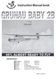
4-CHANNEL RADIO SET UP(STANDARD MODE 2)RUDDERMOVESRIGHTRIGHT AILERONMOVES UPLEFT AILERONMOVES DOWNFULLTHROTTLEELEVATORMOVES DOWN❏ 3. Make certain that the control surfaces and the throttlerespond in the correct direction as shown in the diagram.If any of the controls respond in the wrong direction, usethe servo reversing in the transmitter to reverse the servosconnected to those controls. Be certain the control surfaceshave remained centered. Adjust if necessary.❏ 1. Use a Great Planes AccuThrow gauge, a ruler, or aninclinometer to accurately measure and set the control throwof each control surface as indicated in the chart that follows.If your radio does not have dual rates, we recommendsetting the throws at the LOW rate setting. Under normalcircumstances, and if you have both high and low rates setup, you will perform takeoffs and landings using high rateaileron and elevator and then switch to low rates for flight.With this model, we recommend using high rate rudder onlyduring taxi on the ground. Switch to low rate rudder beforeyou initiate your takeoff.❏ 2. When setting up flaps for this model, please use onlythe amount that we suggest below. This is the right amountrequired to slow the model down without causing it to balloonup excessively.Set the Control ThrowsTo ensure a successful first flight, fly your model set up onlyaccording to the C.G. and control surface throws specified inthis manual. The throws and C.G. are not arbitrary, but havebeen determined through extensive testing and accuraterecord-keeping. This provides you with the best chance forsuccess and enjoyable first flights that should be surprisefree.Additionally, the throws and C.G. shown are true, realdata which will allow the model to perform in the manner inwhich it was intended when flown by a pilot of the skill levelfor which it was intended. DO NOT OVERLOOK THESEIMPORTANT PROCEDURES. A model that is not properlysetup may be unstable and possibly unflyable.The building steps earlier in this manual that show themechanical setup for the elevator, rudder, and aileronlinkages show you the best way to configure the linkages toachieve the proper throws using Futaba servos and a Futabaradio system. If you are using a different radio system oryou cannot achieve the proper control throws using oursuggested linkage configuration, you may have to install thepushrods in different holes on the servo arms or the controlhorns. Keep in mind that changing the throws mechanicallyis preferred to changing them using your radio’s end-pointadjustment. End points can be used to “fine-tune” to get theproper throws.24These are the recommended control surface throws:ELEVATORRUDDERAILERONSFLAPSHIGH RATEUp5/8"[16 mm]12°Right3/4"[19 mm]13°Up7/8"[22 mm]22°Down5/8"[16 mm]12°Left3/4"[19 mm]13°Down7/8"[22 mm]22°11/16"[17 mm]16°LOW RATEUp1/2"[13 mm]9°Right5/8"[16 mm]11°Up5/8"[16 mm]15°Down1/2"[13 mm]9°Left5/8"[16 mm]11°Down5/8"[16 mm]15°
Balance the Model (C.G.)At this stage the model should be in ready-to-fly conditionwith all of the systems in place including the motor, prop,landing gear, radio system, wheel pants, struts, and batteryhatch (canopy).❏ 2. Strap the battery to the battery tray, but do not connectit. Fit the canopy. Suspend the model upright by placing yourfingers on the marks you made.❏ 1. Turn the model over and mark the C.G. location on thebottom of the wing using a felt-tip pen. The C.G., or balancepoint, is located at 2-1/4" [57mm] back from the leading edgeof the wing at the wing root. This is where your plane shouldbalance and fly for the first few flights. Note: It is permissibleto fly the airplane with the C.G. up to 1/4" [6.4mm] forward or1/4" [6.4mm] aft of this point. Do not fly outside of the listedC.G. range!To ensure a successful first flight, fly your Mr. Mulligan setup only according to the C.G. and control surface throwsspecified in this manual. The throws and C.G. are notarbitrary, but have been determined through extensivetesting and accurate record-keeping. This provides youwith the best chance for success and enjoyable first flightsthat should be surprise-free. Additionally, the throws andC.G. shown are true, real data which will allow the model toperform in the manner in which it was intended when flownby a pilot of the skill level for which it was intended. DONOT OVERLOOK THESE IMPORTANT PROCEDURES.A model that is not properly setup will be dangerous,unstable, and possibly unflyable.❏ 3. If the tail drops, the model is “tail heavy” and the batterypack and/or receiver must be shifted forward or weight mustbe added to the nose to balance. If the nose drops, themodel is “nose heavy” and the battery pack and/or receivermust be shifted aft or weight must be added to the tail tobalance. If possible, relocate the battery pack and receiverto minimize or eliminate any additional ballast required. Ifadditional weight is required, nose weight may be easilyadded by using a “spinner weight” (GPMQ4645 for the 1 oz.[28g] weight, or GPMQ4646 for the 2 oz. [57g] weight). Ifspinner weight is not practical or is not enough, use GreatPlanes (GPMQ4485) “stick-on” lead. A good place to addstick-on nose weight is to the structure around the firewall(don’t attach weight to the cowl—it is not intended to supportweight). Begin by placing incrementally increasing amountsof weight on the bottom of the fuse over the firewall until themodel balances. Once you have determined the amount ofweight required, it can be permanently attached. If required,tail weight may be added by cutting open the bottom of thefuse and gluing it permanently inside.Note: Do not rely upon the adhesive on the back of the leadweight to permanently hold it in place. Use #2 sheet-metalscrews or epoxy to permanently hold the weight in place.❏ 4. IMPORTANT: If you found it necessary to add anyweight, recheck the C.G. after the weight has been installed.Balance the Model Laterally❏ 1. With the wings level, have an assistant help you liftthe model by the propeller shaft and the bottom of the fuseunder the TE of the fin. Do this several times.❏ 2. If one wing always drops when you lift the model, itmeans that side is heavy. Balance the airplane by addingweight to the other wing tip. An airplane that has been laterallybalanced will track better in loops and other maneuvers.25
PREFLIGHTIdentify Your ModelNo matter if you fly at an AMA sanctioned R/C club site orif you fly somewhere on your own, you should always haveyour name, address, telephone number and AMA number onor inside your model. It is required at all AMA R/C club flyingsites and AMA sanctioned flying events. Fill out the includedidentification tag on page 29 and place it on or inside yourmodel.Balance PropellersCarefully balance your propeller and spare propellers beforeyou fly. An unbalanced prop can be the single most significantcause of vibration that can damage your model. Not onlywill motor mounting screws loosen, possibly with disastrouseffect, but vibration may also damage your radio gear.We use a Top Flite Precision Magnetic Prop Balancer(TOPQ5700) in the workshop and keep a Great PlanesFingertip Prop Balancer (GPMQ5000) in our flight box.MOTOR SAFETY PRECAUTIONSFailure to follow these safety precautions may resultin severe injury to yourself and others.• Get help from an experienced pilot when learning tooperate electric motors.• Use safety glasses when operating motors.• Do not operate the motor in an area of loose gravel or sand;the propeller may throw such material in your face or eyes.• Keep your face and body as well as all spectators awayfrom the plane of rotation of the propeller as you operatethe motor.• Keep these items away from the prop: loose clothing, shirtsleeves, sweater strings, ties, scarves, long hair or looseobjects such as pencils or screwdrivers that may fall out ofshirt or jacket pockets into the prop.• Always keep your radio on when plugging the motorbatteries into the ESC.• Stay clear of the propeller at all times: Some ESC units donot have safety arming features, so any movement of thethrottle stick may cause the propeller to turn.• Always use a charger designed to charge LiPo batteries forcharging the LiPo flight battery.• Never leave the LiPo battery unattended while charging. Ifthe battery becomes hot, discontinue charging.AMA SAFETY CODE (EXCERPTS)Read and abide by the following excerpts from the Academyof Model Aeronautics Safety Code. For the complete SafetyCode refer to Model Aviation magazine, the AMA web site orthe Code that came with your AMA license.Range CheckGeneral1) I will not fly my model aircraft in sanctioned events, air shows,When you get to your flying site ground check the operationalor model flying demonstrations until it has been proven to berange of the radio before the first flight of the day. With theairworthy by having been previously, successfully flight tested.transmitter antenna collapsed or the transmitter in “powerdown” mode and the receiver and transmitter on, you should 2) I will not fly my model aircraft higher than approximatelybe able to walk at least 100 feet away from the model and 400 feet within 3 miles of an airport without notifying thestill have control. Have an assistant stand by your model airport operator. I will give right-of-way and avoid flying in theand, while you work the controls, tell you what the control proximity of full-scale aircraft. Where necessary, an observersurfaces are doing. Repeat this test with the motor running shall be utilized to supervise flying to avoid having models flyat various speeds with an assistant holding the model, using in the proximity of full-scale aircraft.hand signals to show you what is happening. If the control 3) Where established, I will abide by the safety rules for thesurfaces do not respond correctly, do not fly! Find and correct flying site I use, and I will not willfully and deliberately fly mythe problem first. Look for loose servo or battery connections, models in a careless, reckless and/or dangerous manner.damaged wires or a damaged receiver crystal from a previouscrash in another model. One other possible source of radio5) I will not fly my model unless it is identified with my name“noise” that could cause interference is the arrangement andand address or AMA number, on or in the model. Note: Thisrelative location of the receiver, receiver antenna and motordoes not apply to models while being flown indoors.wires. If possible, remount the receiver in a different location 7) I will not operate models with pyrotechnics (any deviceor reroute some of the wires. Then try the range check again. that explodes, burns, or propels a projectile of any kind).26
Radio Control1) I will have completed a successful radio equipment groundcheck before the first flight of a new or repaired model.2) I will not fly my model aircraft in the presence of spectatorsuntil I become a qualified flier, unless assisted by anexperienced helper.3) At all flying sites a straight or curved line(s) must beestablished in front of which all flying takes place with theother side for spectators. Only personnel involved with flyingthe aircraft are allowed at or in the front of the flight line.Intentional flying behind the flight line is prohibited.4) I will operate my model using only radio control frequenciescurrently allowed by the Federal Communications Commission.5) I will not knowingly operate my model within threemiles of any pre-existing flying site except in accordancewith the frequency sharing agreement listed [in thecomplete AMA Safety Code].9) Under no circumstances may a pilot or other persontouch a powered model in flight; nor should any part of themodel other than the landing gear, intentionally touchthe ground, except while landing.❏ 11. Reinforce holes for wood screws with thin CA whereappropriate (servo mounting screws, etc.).❏ 12. Check that all servo connectors are fully plugged intotheir respective channels on the receiver.❏ 13. Make sure any servo extension cords you may haveused do not interfere with other systems (servo arms,pushrods, etc.).❏ 14. Check the receiver for secure attachment. This mustnot be “stuffed into place.”❏ 15. Balance your model laterally as explained in theinstructions.❏ 16. Check the C.G. according to the measurementsprovided in the manual.❏ 17. Place your name, address, AMA number and telephonenumber on or inside your model.❏ 18. Fully charge your transmitter battery and check thebattery voltage after it is charged.❏ 19. Range-check your radio at the flying field.❏ 20. Confirm that all controls operate in the correct directionand the throws are set up according to the manual.❏ 21. If you wish to photograph your model, do so beforeyour first flight.FLYINGCHECK LISTDuring the last few moments of preparation your mind maybe elsewhere anticipating the excitement of the first flight.Because of this, you may be more likely to overlook certainchecks and procedures that should be performed beforethe model is flown. To help avoid this, a check list is providedto make sure these important areas are not overlooked.Many are covered in the instruction manual, so whereappropriate, refer to the manual for complete instructions.Be sure to check the items off as they are completed.❏ 1. Check the motor for secure attachment.❏ 2. Check the cowl for secure attachment.❏ 3. Balance your propeller (and spare propellers).❏ 4. Tighten the propeller nut and check to make sure that aprop washer is in place.❏ 5. Rotate the propeller a full turn. Check for free rotationof the prop. Make sure that the dummy engine does notinterfere with rotation.❏ 6. Check the wheels for free rotation, the axles and landinggear for security, and add a drop of light machine oil to theaxles.❏ 7. Make sure all hinges are securely glued in place.❏ 8. Check the control horns for secure attachment to thecontrol surfaces.❏ 9. Pull/push on each of the pushrods and check to see thatthe adjustable pushrod connectors do not slip.❏ 10. Check the servo arms for secure attachment and makesure that the arm screws are in place and are tight.CAUTION (THIS APPLIES TO ALL R/C AIRPLANES): If,while flying, you notice an alarming or unusual sound suchas a low-pitched “buzz,” this may indicate control surfaceflutter. Flutter occurs when a control surface (such as anaileron or elevator) or a flying surface (such as a wing orstab) rapidly vibrates up and down (thus causing the noise).In extreme cases, if not detected immediately, flutter canactually cause the control surface to detach or the flyingsurface to fail, thus causing loss of control followed byan impending crash. The best thing to do when flutter isdetected is to slow the model immediately by reducingpower, then land as soon as safely possible. Identify whichsurface fluttered (so the problem may be resolved) bychecking all the servo grommets for deterioration or signs ofvibration. Make certain all pushrod linkages are secure andfree of play. If it fluttered once, under similar circumstancesit will probably flutter again unless the problem is fixed.Some things which can cause flutter are; Excessive hingegap; Not mounting control horns solidly; Poor fit of clevispin in horn; Side-play of wire pushrods caused by largebends; Excessive free play in servo gears; Insecure servomounting; and one of the most prevalent causes of flutter;Flying an overpowered model at excessive speeds.TakeoffThe goals of your first flight should be to trim the airplaneBefore you get ready to takeoff, see how the model handleson the ground by doing a few practice runs at low speeds onthe runway. Hold “up” elevator to keep the tail wheel on theground. If necessary, adjust the tail wheel so the model willroll straight down the runway.27
Takeoff directly into the wind. Gradually advance the throttlewhile holding a bit of up elevator to keep the tail on the groundto maintain tail wheel steering. Also start applying right rudder.If the throttle is advanced too quickly, the plane will want toturn quickly to the left. As the model gains speed, decreaseup elevator allowing the tail to come off the ground. Gain asmuch speed as your runway and flying site will practicallyallow before gently applying up elevator, lifting the model intothe air. Be smooth on the elevator stick, allowing the model toestablish a gentle climb to a safe altitude before turning intothe traffic pattern.FlightFor reassurance and to keep an eye on other traffic, it is agood idea to have an assistant on the flight line with you. Onthe first flight the assistant can help you adjust the trims.In the air, the Mister Mulligan flies similar to a sport plane.It can perform the basic aerobatic maneuvers; loops, rolls,stall turns and wing overs. Be mindful of the flight time. Withelectric planes it is best to have a timer set so that the planecan be landed with power to spare, just in case you have toabort the landing and go around. A dead stick with an electricplane is the same as a dead stick with a glow plane. Risky!LandingRBefore the battery power drops, make a few passes withthe flaps down to see how the plane slows down. If this isyour first plane equipped with flaps, here are a couple ofnotes on how to land with flaps. Only lower the flaps at halfthrottle or less. When the flaps are lowered, the plane willballoon up slightly, then, level off as the speed slows. On finalapproach, keep the power on and control the descent withthe throttle. The plane will land slower with flaps than without.Don’t let the plane get to slow, even with flaps the plane cantip stall if it gets too slow.One final note about flying the Mister Mulligan. Have a goal orflight plan in mind for every flight. This can be learning a newmaneuver(s), improving a maneuver(s) you already know,or learning how the model behaves in certain conditions(such as on high or low rates). This is not necessarily toimprove your skills (though it is never a bad idea!), but moreimportantly so you do not surprise yourself by impulsivelyattempting a maneuver and suddenly finding that you’ve runout of time, altitude or airspeed. Every maneuver should bedeliberate, not impulsive. For example, if you’re going to do aloop, check your altitude, mind the wind direction (anticipatingrudder corrections that will be required to maintain heading),remember to throttle back at the top, and make certain youare on the desired rates (high/low rates). A flight plan greatlyreduces the chances of crashing your model just because ofpoor planning and impulsive moves. Remember to think.Have a ball!But always stay in control and fly in a safe manner.GOOD LUCKAND GREAT FLYING!28
CutAlign these dashed lineswith the other windows.DOOR TEMPLATECutNote: Door is onlyon RH side.This model belongs to:NameAddressCity, State, ZipPhone NumberAMA Number29
NOTES30