LOGO 550 SX - Mikado
LOGO 550 SX - Mikado
LOGO 550 SX - Mikado
Create successful ePaper yourself
Turn your PDF publications into a flip-book with our unique Google optimized e-Paper software.
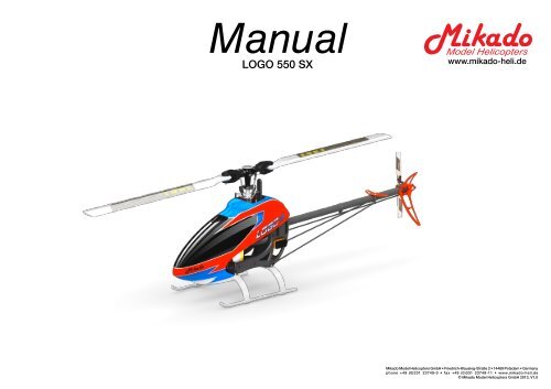
Manual<strong>LOGO</strong> <strong>550</strong> <strong>SX</strong>www.mikado-heli.de<strong>Mikado</strong> Model Helicopters GmbH • Friedrich-Klausing-Straße 2 • 14469 Potsdam • Germanyphone +49 (0)331 23749-0 • fax +49 (0)331 23749-11 • www.mikado-heli.de© <strong>Mikado</strong> Model Helicopters GmbH 2013, V1.0
1 MainframeBag 11Bag 13x1716x M2,53x3x7x3SW5x592x3x17Before you combine the two sides of the mainframe, attach the two belt tensioners (#4089,bag 6).Using the rod M2.5x60 from bag 7, position all14 nylon nuts in the right side frame.4x2x10x3x5x2,5M2,5x8M2,5x1010x19x54x4x4xM3x10M2,5x16M2,5x122xM3x20M2,5x8M2,5x12M3x10M2,5x12M2,5x16 (4x)You should position the motor pinionon the motor shaft, before you mountthe motor plate. You may also mountthe motor pinion at a later stage, butthe process will be more cumbersome.For reading on how to mountthe motor pinion, please flip to page 9.M3x10M3x20All parts shown in the boxes are displayed in real size.Manual <strong>LOGO</strong> <strong>550</strong><strong>SX</strong> - ©<strong>Mikado</strong> Model Helicopters GmbH - Page 3
2 Tail RotorBag 51Bag 56x8x0,5smaler inner Ølarger inner ØNO Loctite here!M3x165x8x3M3x10Apply grease here inside andApply grease onbearing and sleeveApply Loctite only in the threadedsection inside the tail rotor hub!a outside!b cM3 StopdIt is very important that you grease the 3x4x3.5 sleeve on which the thrustbearing is mounted. You mustgrease the inside and the outside of the sleeve. Note also: Apply Loctite only to the inside of the tail rotorhub. Any Loctite inside of the sleeve will make the tail blad holders run unsmooth. Therefore, do not useLoctite on the thread of the screw.2xBag 56x8x0,51M3x83x10x42xM3x103x4x11Glue ball bearingsusing 5min. Epoxy4x2x5x8x3M3x16M3x35 (5x)M2,5x65x13x42x2x2x4x8x3,5M33x4x3,53x81xM3x325x7x2,35x1xM3Bag 5M2,5x63Bag 5227mm31x2xM3x85x275xM3x353x5x53x6x2,5M3x14M2x103x5x0,51x1x1x1x1x2x3x5x5M2x10Kugel/ball/Rotule3x5x0,5M3x143x6x2,5227mmM3 Stop(5x)2x1x2x2x3x4x123x10x45x13x45x7x2,3Manual <strong>LOGO</strong> <strong>550</strong><strong>SX</strong> - ©<strong>Mikado</strong> Model Helicopters GmbH - Page 4
3 Tail BoomBag 6 • Bag 11M3x402x1x1x2x4x2x2xBag 6M3M2x6M2 StopM3x16Kugel/ball/Rotule Ø6x3M3x403mm2x4xBag 6 + 11Ø4x565 mmM2x65 Min. EpoxyBall Ø6 mmM3x16 (2x)M2M3 StopBag 5M3x3Bag 6 + 11Ø5x450 mm5 Min. EpoxyBall Ø6 mmAttach the ball links so that the engravednumber is on the outer surface pointingtowards you.Manual <strong>LOGO</strong> <strong>550</strong><strong>SX</strong> - ©<strong>Mikado</strong> Model Helicopters GmbH - Page 5
4 Main Gear & Tail Boom AssemblyBag 2 • Bag 3 • Bag 81 24Bag 22x1x1x10x16x0,53x16M2,5x83Tighten tooth belt:Pull tail rotor backwards and tighten screwsPush in tail boom until locked.4x4x4xM3M3x3Bag 8M3x1010x16x0,5M3x20M3x8M3 Stopp (4)Swashplate bag 3M3x10M3x10Secure scids using set screws 3x3.Attach the tail boom with a screw 2.2x6Tighten the pivot boltsvery carefully. Do notovertighten them, as (7x)they will break off.Manual <strong>LOGO</strong> <strong>550</strong><strong>SX</strong> - ©<strong>Mikado</strong> Model Helicopters GmbH - Page 6
5 Servo InstallationBag 1 • Bag 9<strong>LOGO</strong> Rotor Head (V-Stabi, flybarless head)16 mm 16 mm 16 mm 14-16mm41x2x3x5x2Bag 1M3x472,2x13 (4x)2If you are installing Futaba servos, add thedistance plate for the two aileron servos.5Bag 94xM2,5x1012x 2,2x133xM2x101xM2x12Bag 94x9x M23xM2,5x35M2,5x10 (4x)(4x)62,2x13(4x)Aileron left Aileron right Elevator RudderBag 197Apply a small amountof oil to the rotor shaft.Attach the ball links so that the engravednumber is on the outer surfacepointing towards you.3823 mmManual <strong>LOGO</strong> <strong>550</strong><strong>SX</strong> - ©<strong>Mikado</strong> Model Helicopters GmbH - Page 7
7 Mounting the Motor 8 Mounting the CanopyBag 1Bag 1,21For mounting the new motor counterbearing with rotorshaftsuport, please follow these steps: First, mount themain gear, the rotor shaft assembly and all shims. Secureassembly with the 10 mm c-clip (Picture 2). The main gearwill have 0.5 mm axial play. This is normal and will facilitatethe mounting and positioning of the pinion later on.Now mount the motor and the counterbearing. Once themotor position is set (please ensure correct gear backlash!),please screw the rotorshaft support onto the counterbearing,using the three M3x6 screws.4x1x2x3xM3x85x10x1M3x6Bag 2M4x324x10x16x0,51x10x16x0,22Bag 15x10x110x16x0,5M4x32Please mount the motor, motor plate, pinionand counterbearing as illustrated in the abovepicture. When positioning the pinion, pleaseensure that it sits exactly on the ball bearing ofthe counterbearing with only one shim (5x10x1)inbetween. Also make sure that the M3 set screwsits on the flattened area of the motor shaft.5x10x110x16x0,510x16x0,5Installation of the Motor PinionScrew the motor pinion onto the motor shaft, making sure that itcan still be moved. Now mount the motor on the motor plate andmove the pinion so it is aligned well with the main gear. As visualhelp for aligning the pinion you may use the small ridge whichseparates the two parts of the pinion. When the pinion is alignedcorrectly it will easily engage with the main gear. If the pinion doesnot engage with the main gear, it is not correctly aligned. After thepinion is correctly aligned, take the motor out of the mainframeand tighten the set screw.Gear BacklashMove the motor with the pinion until it is limited by the gear. Tightenone of the M4x32 screws slightly. You must still be able to swivelthe motor around its own axis. In this way you can easily determinethe correct distance between the main gear and the pinion.There should be no (!) gear backlash. At the same time, the motorshould not (!) exert any pressure onto the running surface of themain gear. After you have determined the correct distance, tightenthe second M4x32 screw.Manual <strong>LOGO</strong> <strong>550</strong><strong>SX</strong> - ©<strong>Mikado</strong> Model Helicopters GmbH - Page 9
9 Radio and Battery13Position of servo arms for the tail rotor when sticks are centeredPosition for V-Bar gyro2Position for Mini V-Bar4Position of servo arms for the aileron servoswhen sticks are centered (0 deg. Pitch)5 67speedcontrollerBattery:Attach the battery with the 3Velcros.Position of LiPo batteryfor the power supply of receiver.VelcroManual <strong>LOGO</strong> <strong>550</strong><strong>SX</strong> - ©<strong>Mikado</strong> Model Helicopters GmbH - Page 10
10 Overview Chassis23834192406423644102132940914072 (20mm)4713 (22mm)41912071 (14x)4075 (205mm)4620 (199mm)19389304089238513294103195342362010 (10x16x0,5)2009 (10x16x0,2)2010191546514094 M07-1534183 M1-106, 11mm4621 M1-106, 13mm405740992074 19584059406740581344195419744622 (6mm Motorshaft)4714 (5mm Motorshaft)46744311 white <strong>LOGO</strong> 6002496 black <strong>LOGO</strong> 6002775 black <strong>LOGO</strong> 5004311 white <strong>LOGO</strong> 50019204290 black <strong>LOGO</strong> 500/6004288 white <strong>LOGO</strong> 500/600Manual <strong>LOGO</strong> <strong>550</strong><strong>SX</strong> - ©<strong>Mikado</strong> Model Helicopters GmbH - Page 11
11 Overview Tail Rotor4235307719614627427330694107461524474145040744634 (25mm)4719 (22mm)7271956246246252466463420744343 EDGE 924344 EDGE 954345 EDGE 1054630207446304137 (25mm)4717 (22mm)4096 (25mm)4718 (22mm)4626 (neon red)4715 <strong>LOGO</strong> <strong>550</strong> <strong>SX</strong> (640mm)4098 <strong>LOGO</strong> 6004354 <strong>LOGO</strong> 600 SE4073 <strong>LOGO</strong> 6004355 <strong>LOGO</strong> 600 SE4721 <strong>550</strong> <strong>SX</strong>4097 (SET) <strong>LOGO</strong> 6004354 (SET) <strong>LOGO</strong> 600 SE4720 (SET) <strong>LOGO</strong> <strong>550</strong> <strong>SX</strong>4081 (730XL <strong>LOGO</strong> 600)4325 (770XL <strong>LOGO</strong> 600 SE)Manual <strong>LOGO</strong> <strong>550</strong><strong>SX</strong> - ©<strong>Mikado</strong> Model Helicopters GmbH - Page 12
12 Overview V-Bar Head20792314197204051234915742350404923514619 (for mainshaft #4620)4631 (for main shaft #4075)20762347475046184133930191623301586 (60mm)1579 (65mm)1588 (40mm)1565www.mikado-heli.deConstruction & Rendering: Mehran Mahinpour Tirooni, André Doil • Layout & Realisation: CDT, André DoilManual <strong>LOGO</strong> <strong>550</strong><strong>SX</strong> - ©<strong>Mikado</strong> Model Helicopters GmbH - Page 13


