Instruction Manual book - black horse model
Instruction Manual book - black horse model
Instruction Manual book - black horse model
- No tags were found...

Create successful ePaper yourself
Turn your PDF publications into a flip-book with our unique Google optimized e-Paper software.
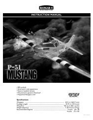
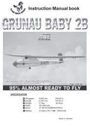
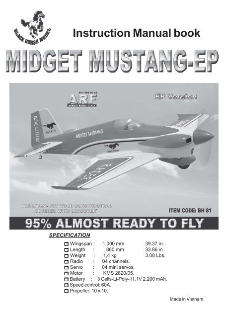
<strong>Instruction</strong> <strong>Manual</strong> <strong>book</strong>SPECIFICATION Wingspan : 1,000 mm 39.37 in. Length : 860 mm 33.86 in. Weight : 1,4 kg 3.08 Lbs. Radio : 04 channels. Servo : 04 mini servos. Motor : KMS 2820/05. Battery : 3 Cells-Li-Poly-11.1V 2.200 mAh. Speed control: 60A. Propeller: 10 x 10.Made in Vietnam.
MIDGET MUSTANG-EP - Item code: BH81 .<strong>Instruction</strong> <strong>Manual</strong>This instruction manual is designed to help you build a great flying aeroplane. Please read thismanual thoroughly before starting assembly of your MIDGET MUSTANG - EP. Use the parts listingbelow to identify all parts.WARNING.Please be aware that this aeroplane is not a toy and if assembled or used incorrectly it iscapable of causing injury to people or property. WHEN YOU FLY THIS AEROPLANE YOUASSUME ALL RISK & RESPONSIBILITY.If you are inexperienced with basic R/C flight we strongly recommend you contact your R/C supplierand join your local R/C Model Flying Club. R/C Model Flying Clubs offer a variety of trainingprocedures designed to help the new pilot on his way to successful R/C flight. They will also be ableto advise on any insurance and safety regulations that may apply.TOOLS & SUPPLIES NEEDED.Thick cyanoacrylate glue.30 minute epoxy.5 minute epoxy.Hand or electric drill.Assorted drill bits.Modelling knife.Straight edge ruler.2mm ball driver.Phillips head screwdriver.220 grit sandpaper.90° square or builder’s triangle.Wire cutters.Masking tape & T-pins.Thread-lock.Paper towels.PARTS LISTING.FUSELAGE ASSEMBLY (1) Fuselage.WING ASSEMBLY(1) Right wing half with pre-installedaileron.(1) Left wing half with pre-installedaileron.Tail section assembly(1) Vertical stabilizer with preinstalledrudder.(1) Horizontal stabilizer with preinstalledelevator halves.Some more parts.HARDWARE PACKCOWLING.Landing gear.....SUGGESTION.To avoid scratching your new airplane, do notunwrap the pieces until they are needed forassembly. Cover your workbench with an oldtowel or brown paper, both to protect the aircraftand to protect the table. Keep a couple ofjars or bowls handy to hold the small parts afteryou open the bag.NOTE.Please trial fit all the parts. Make sure you havethe correct parts and that they fit and are alignedproperly before gluing! This will assure properassembly.MIDGET MUSTANG-EPIARF is handmade from natural materials, every plane isunique and minor adjustments may have to bemade. However, you should find the fit superiorand assembly simple.The painted and plastic parts used in this kitare fuel proof. However, they are not tolerantof many harsh chemicals including the following:paint thinner, C/A glue accelerator, C/A gluedebonder and acetone. Do not let these chemicalscome in contact with the colors on thecovering and the plastic parts.2
MIDGET MUSTANG-EP - Item code: BH81INSTRUCTION MANUALSAFETY PRECAUTION.+ This is not a toy+ Be sure that no other flyers are using yourradio frequency.+ The glow plug clip must be securelyattached to the glow plug.+ Do not flip the propeller with your fingers.+ Keep loose clothing and wires away fromthe propeller.+ Do not start the motor if people are near.Do not stand in line with the side of the propeller.REPLACEMENT LARGE PARTSC.D. E.I. AILERON.1.INSTALLING THE AILERON SERVOS.B.B. 1) Install the rubber grommets and brasseyelets onto the aileron servos.A.F.A. Cowling.B. Wing panel.C. Fuselage.D . Horizon stabilizer.E. Vertical stabilizer.F. Aluminium wing dihedral brace.REPLACEMENT SMALL PARTS1. 2. 3.2.Bottom side4.Aileron3 x15 mm1. Spinner.2. Wheel spant.3. Wheels4. Aluminium landing gear. Aileron3
MIDGET MUSTANG-EP - Item code: BH81INSTRUCTION MANUALStraitgh line.2x10mm. 2) Insert aileron control horn to the aileron. 3) Drill two 2mm holes through the aileronusing the control horn as a guide and screwthe control horn in place.SecureBottom sideDrill 2mmholeINSTALLING THE AILERONCONTROL HORN.2mm X 12mm. 1) Using a ruler & pen to draw a straightline as below picture.Pen.Secure.5
MIDGET MUSTANG-EP - Item code: BH81 .<strong>Instruction</strong> <strong>Manual</strong>INSTALLING THE AILERONLINKAGES.MAIN GEAR INSTALATION.PARTS REQUIRED3 x15 mm 4 x 35 mmAileron pushrod.Aileron pushrod.Remove coveringBottom side6Top sideRepeat the procedure for the other winghalf.
MIDGET MUSTANG-EP - Item code: BH81INSTRUCTION MANUALC/A glueSecureSecureDrill 4mmholeRepeat the procedure for the other winghalf.7
MIDGET MUSTANG-EP - Item code: BH81 .<strong>Instruction</strong> <strong>Manual</strong>INSTALLING ELECTRIC MOTOR.See pictures below:PushC/A glue.3 x 15mmEpoxy glue.Motor mount woodC/A glue.Epoxy glue.8
MIDGET MUSTANG-EP - Item code: BH81INSTRUCTION MANUALLeft sideCOWLING. 1. Slide the fiberglass cowl over the engineand line up the back edge of the cowl withthe marks you made on the fuselage.Rotor shaftSecure.Motor 2. While keeping the back edge of thecowl flush with the marks, align the front ofthe cowl with the crankshaft of the engine. Thefront of the cowl should be positioned so thecrankshaft is in nearly the middle of the cowlopening. Hold the cowl firmly in place usingpieces of masking tape. 3. Slide the cowl back over the engineand secure it in place using four wood screws.See picture below.Front view. 4. Install the muffler and muffler extensiononto the engine and make the cutout in thecowl for muffler clearance. Connect the fueland pressure lines to the carburetor, mufflerand fuel filler valve.Right sideRight side9
MIDGET MUSTANG-EP - Item code: BH81 .<strong>Instruction</strong> <strong>Manual</strong>3 x 12mmRight sideMachine screw.Secure.Left sideELEVATOR INSTALLATION.SERVO INSTALLATION. 1. Install the rubber grommets and brasscollets into the elevator servo. Test fit the servointo the servo tray. 2. Mount the servo to the tray using themounting screws provided with your radio system.Bottom side.INSTALLING THE SPINNER.Install the spinner backplate, propeller andspinner cone. The spinner cone is held inplace using two 3mm x 12mm wood screws.3 x 12mm10
MIDGET MUSTANG-EP - Item code: BH81INSTRUCTION MANUALC/A glueHORIZONTAL STABILIZER.See pictures below:C/A glueCheck to mark sure the wing and stabilizerare paralell. If they are not, lightly sandthe opening in the fuselage for the stabilizeruntil the stabilizer is paralell to the wing.C/A glueTop sideC/A glueBottom side 1. Draw a center line onto the horizontalstabilizer. Then slide the horizontal into thefuselage.C/A glueCenter line 2 Using a <strong>model</strong>ing knife, cut away thecovering from the fuselage for the stabilizerand remove it.11
MIDGET MUSTANG-EP - Item code: BH81 .<strong>Instruction</strong> <strong>Manual</strong>Remove covering 3. Mark the shape of the vertical on the leftand right sides onto the horizontal stabilizerusing a felt-tip pen 5. When you are sure that everything isaligned correctly, mix up a generous amountof 30 minute epoxy. Apply a thin layer to thetop and bottom of the stabilizer mounting areaand to the stabilizer mounting platform sidesin the fuselage. Slide the stabilizer in place andre-align. Double check all of your measurementsone more time before the epoxy cures.Remove any excess epoxy using a papertowel and rubbing alcohol and hold the stabilizerin place with T-pins or masking tape.Epoxy glueMark lineBottom side 4. Remove the stabilizer. Using the linesyou just drew as a guide, carefully remove thecovering from between them using a <strong>model</strong>ingknife.When cutting through the coveringto remove it, cut with only enough pressureto only cut through the covering it’sself. Cutting into the balsa structure mayweaken it. This could lead to possible failureduring flight6. After the epoxy has fully cured, removethe masking tape or T-pins used to hold thestabilizer in place and carefully inspect theglue joints. Use more epoxy to fill in anygaps that were not filled previously andclean up the excess using a paper towel andrubbing alcohol.Remove coveringC/A glue12
MIDGET MUSTANG-EP - Item code: BH81INSTRUCTION MANUALC/A glueC/A glueDrill a hole 2mmdiameter.ELEVATOR CONTROL HORN INSTALLA-TION.Elevator control horn install as same as theway of aileron control horn. Please see picturesbelow.2*12mm.Secure.ELEVATOR PUSHROD INSTALLATION.Mark pointElevator and rudder pushrod install as sameas the way of aileron pushrod.M2M2 lock nut.13
MIDGET MUSTANG-EP - Item code: BH81 .<strong>Instruction</strong> <strong>Manual</strong>SecureSecureElevatorpushrodElevatorpushrodCutBottom sideTop sideElevator servo.SecureC/A glue.Elevator pushrod.14
MIDGET MUSTANG-EP - Item code: BH81INSTRUCTION MANUALC/A glueElevator servo.C/A glueC/A glue.VERTICAL INSTALLATION.Rudder servo install as same as method ofelevator servo. See picture below:C/A glueC/A glue 1. Using a <strong>model</strong>ing knife cut away thecovering from the end of fuselage for the rudderhinge.15
MIDGET MUSTANG-EP - Item code: BH81 .<strong>Instruction</strong> <strong>Manual</strong> Also carefully remove the covering fromthe horizontal fin as below the lines whichyou drew as same picture below.RemovecoveringHinge slot. 2. Put the rudder into the fuselage assame as picture below. 3. Mark the shape of the vertical on theleft and right side of the rudder on to the horizontalstabilizer using a felt-tip pen. 5. Put the vertical stabilizer back inplace. Using a triangle, check to ensurethat the vertical stabilizer is aligned 90 degreeto the horizontal stabilizer.Mark point.Epoxy glue 4. Now, remove the rudder and using a<strong>model</strong>ing knife, carefully cut just inside themarked lines and remove the film of the rudder.Just as you did with the horizontal stabilizer,make sure you only press hard enoughto cut the film, not the balsa rudder.Remove covering. 6) When you are sure that everything is aaligned correctly, mix up a generous amountof 30 minute epoxy. Apply a thin layer to theslot in the mounting platform and to the verticalstabilizer mounting area. Apply epoxy tothe lower rudder hinge. Set the stabilizer inplace and re-align. Double check all of yourmeasurements once more before the epoxycures. Remove any excess epoxy using apaper towel and rubbing alcohol and hold thestabilizer in place with T-pins or masking tape.Allow the epoxy to fully cure before proceeding.16
MIDGET MUSTANG-EP - Item code: BH81INSTRUCTION MANUALEpoxy glueRUDDER CONTROL HORN INSTALLA-TION.Rudder control horn install as same as theway of aileron control horn. Please see picturesbelow.Epoxy glueC/A glueMark pointC/A glueC/A glueDrill a hole2mm diameter17
MIDGET MUSTANG-EP - Item code: BH81 .<strong>Instruction</strong> <strong>Manual</strong>C/A glueElevatorpushrod.Elevatorpushrod.SecureRudderpushrod.RUDDER PUSHROD INSTALLATION.Rudder pushrod install as same as the wayof aileron pushrod.Elevatorpushrod.M2M2 lock nut.Rudderpushrod.Ruddercontrol hornRudder pushrod.C/A glueRudder servo.INSTALLING THE RECEIVER AND BATTERY. 1. Plug the servo leads and the switchlead into the receiver. You may want to plugan aileron extension into the receiver to makeplugging in the aileron servo lead easierwhen you are installing the wing . Plug thebattery pack lead into the switch.18
MIDGET MUSTANG-EP - Item code: BH81INSTRUCTION MANUAL 2. Wrap the receiver and battery pack inthe protective foam to protect them from vibration.Use a rubber band or masking tape tohold the foam in place. 3. Position the battery pack and receiverbehind the fuel tank. Use two tie wraps tohold the battery and receiver securely in place.As pictures below.Do not permanently secure the receiverand battery until after balancing the <strong>model</strong>. 4. Using a 2mm drill bit, drill a hole throughthe side of the fuselage, near the receiver,for the antenna to exit.BatteryTie wrap.Tie wrap.ReceiverBatteryWING ATTACHMENT.Locate the aluminium wing dihedral brace.*** Test fit the aluminium tube dihedral braceinto each wing haft. The brace should slide ineasily. If not, use 220 grit sand around theedges and ends of the brace until it fits properly.19
MIDGET MUSTANG-EP - Item code: BH81 .<strong>Instruction</strong> <strong>Manual</strong>Secure.WING ATTACHMENT.See picture wing attach to fuselage.Wing bolt.Installing the fuselage hatch as same as picturebelow.Wing bolt.20
MIDGET MUSTANG-EP - Item code: BH81INSTRUCTION MANUALBALANCING. 1) It is critical that your airplane be balancedcorrectly. Improper balance will causeyour plane to lose control and crash.THE CENTER OF GRAVITY IS LOCATED80MM BACK FROM THE LEADING EDGEOF THE WING. 2) Mount the wing to the fuselage. Using acouple of pieces of masking tape, place themon the top side of the wing 80mm back fromthe leading edge, at the fuselage sides. 3. Turn the airplane upside down. Placeyour fingers on the masking tape and carefullylift the plane .Accurately mark the balance point on the topof the wing on both sides of the fuselage. Thebalance point is located 80mm back from theleading edge. This is the balance point atwhich your <strong>model</strong> should balance for your firstflights. Later, you may wish to experiment byshifting the balance up to 10mm forward orback to change the flying characteristics.Moving the balance forward may improve thesmoothness and arrow- like tracking, but itmay then require more speed for take offand make it more difficult to slow down forlanding. Moving the balance aft makes the<strong>model</strong> more agile with a lighter and snappier”feel”. In any case, please start at the locationwe recommend .Lift the <strong>model</strong>. If the tail drops when youlift, the <strong>model</strong> is “tail heavy” and you mustadd weigh* to the nose. If the nose drops, itis “nose heavy” and you must add weight* tothe tail to balance.With the wing attached to the fuselage, allparts of the <strong>model</strong> installed ( ready to fly), andempty fuel tanks, hold the <strong>model</strong> at themarked balance point with the stabilizer level.*If possible, first attempt to balance the <strong>model</strong>by changing the position of the receiver batteryand receiver. If you are unable to obtaingood balance by doing so, then it will be necessaryto add weight to the nose or tail toachieve the proper balance point.CONTROL THROWS. 1) We highly recommend setting up aplane using the control throws listed. 2) The control throws should be measuredat the widest point of each control surface. 3) Check to be sure the control surfacesmove in the correct directions.Ailerons : 12mm up 12mm downElevator : 12mm up 12mm downRudder : 20mm right 20mm leftAileron controlPRE-FLIGHT CHECK.121212122020 1) Completely charge your transmitter andreceiver batteries before your first day of flying. 2) Check every bolt and every glue joint inyour plane to ensure that everything is tightand well bonded. 3) Double check the balance of theairplane. 4) Check the control surface. 5) Check the receiver antenna . It shouldbe fully extended and not coiled up inside thefuselage. 6) Properly balance the propeller.We wish you many safe and enjoyableflights with yourMIDGET MUSTANG -EP.21