Agilent E4438C ESG Vector Signal Generator - Advanced Test ...
Agilent E4438C ESG Vector Signal Generator - Advanced Test ...
Agilent E4438C ESG Vector Signal Generator - Advanced Test ...

Create successful ePaper yourself
Turn your PDF publications into a flip-book with our unique Google optimized e-Paper software.
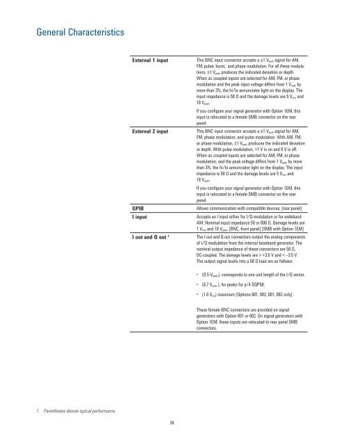
General CharacteristicsExternal 1 inputExternal 2 inputGPIBI inputI out and Q out 1This BNC input connector accepts a ±1 V peak signal for AM,FM, pulse, burst, and phase modulation. For all these modulations,±1 V peak produces the indicated deviation or depth.When ac-coupled inputs are selected for AM, FM, or phasemodulation and the peak input voltage differs from 1 V peak bymore than 3%, the hi/lo annunciator light on the display. Theinput impedance is 50 Ω and the damage levels are 5 V rms and10 V peak.If you configure your signal generator with Option 1EM, thisinput is relocated to a female SMB connector on the rearpanel.This BNC input connector accepts a ±1 V peak signal for AM,FM, phase modulation, and pulse modulation. With AM, FM,or phase modulation, ±1 V peak produces the indicated deviationor depth. With pulse modulation, +1 V is on and 0 V is off.When ac-coupled inputs are selected for AM, FM, or phasemodulation, and the peak voltage differs from 1 V peak by morethan 3%, the hi/lo annunciator light on the display. The inputimpedance is 50 Ω and the damage levels are 5 V rms and10 V peak.If you configure your signal generator with Option 1EM, thisinput is relocated to a female SMB connector on the rearpanel.Allows communication with compatible devices. [rear panel]Accepts an I input either for I/Q modulation or for widebandAM. Nominal input impedance 50 or 600 Ω. Damage levels are1 V rms and 10 V peak. [BNC, front panel] [SMB with Option 1EM]The I out and Q out connectors output the analog componentsof I/Q modulation from the internal baseband generator. Thenominal output impedance of these connectors are 50 Ω,DC-coupled. The damage levels are > +3.5 V and < –3.5 V.The output signal levels into a 50 Ω load are as follows:• (O.5 V peak,), corresponds to one unit length of the I/Q vector.• (0.7 V peak ), for peaks for p/4 DQPSK.• (1.6 V p-p) maximum [Options 601, 602, 001, 002 only].These female BNC connectors are provided on signalgenerators with Option 601 or 602. On signal generators withOption 1EM, these inputs are relocated to rear panel SMBconnectors.1. Parentheses denote typical performance.30