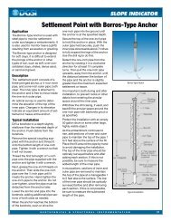
tropic and rely on <strong>in</strong>dustrial type mix<strong>in</strong>g plants and methods. The cement content is difficult tocontrol under ord<strong>in</strong>ary field <strong>in</strong>strumentation <strong>in</strong>stallation circumstances.The amount of bentonite that is required for the above mix<strong>in</strong>g procedure will vary due tofactors mentioned earlier. The amount of bentonite shown <strong>in</strong> Table 1 should only be used as aguide and is also handy for estimat<strong>in</strong>g material quantities shipped to the site. With this methodmore bentonite is required than if water and bentonite was mixed first. This is an advantagefrom the standpo<strong>in</strong>t of want<strong>in</strong>g a low permeability. When the bentonite solids content <strong>in</strong>creases,the density <strong>in</strong>creases and the permeability is lowered. It is another reason for mix<strong>in</strong>g water andcement before add<strong>in</strong>g cement. A lower permeability is generally preferred s<strong>in</strong>ce cementbentoniteshave a higher permeability than high-density bentonite grout or chip seals.4 DIAPHRAGM PIEZOMETERS IN FULLY GROUTED BOREHOLES4.1 Recent experienceIncreas<strong>in</strong>gly, both s<strong>in</strong>gle and multiple vibrat<strong>in</strong>g wire and pneumatic pressure sensors are be<strong>in</strong>gsuccessfully grouted directly <strong>in</strong>to boreholes without sand pockets and bentonite seals. The ideais not new. Thirty years ago, Vaughan <strong>in</strong> London demonstrated that even grouted multiplesmall-diameter standpipes <strong>in</strong> clay were feasible (Vaughan, 1969). Tofani (2000) has used theprocedure for 20 years <strong>in</strong> California for both pneumatic and vibrat<strong>in</strong>g wire piezometers.McKenna (1995) <strong>in</strong> Canada has adopted the fully grouted <strong>in</strong>stallation of piezometer sensorsfollow<strong>in</strong>g extensive field test<strong>in</strong>g and McKenna and others (1994) adopted comb<strong>in</strong>ed <strong>in</strong>cl<strong>in</strong>ometercas<strong>in</strong>g and diaphragm piezometers directly grouted <strong>in</strong>to the same borehole as standard procedures.The US Army Corps of Eng<strong>in</strong>eers, Omaha District adopted fully-grouted vibrat<strong>in</strong>g wirepiezometer <strong>in</strong>stallations and <strong>in</strong>cluded them with deep <strong>in</strong>cl<strong>in</strong>ometer cas<strong>in</strong>g <strong>in</strong>stallations based onrecommendations by the first author (USACE, 1999). But, because the geotechnical communityseems to be so rooted <strong>in</strong> traditional th<strong>in</strong>k<strong>in</strong>g when it comes to seal<strong>in</strong>g a piezometer <strong>in</strong> a borehole,it is counter-<strong>in</strong>tuitive to most eng<strong>in</strong>eers to simply grout the sensors <strong>in</strong> the bor<strong>in</strong>g.Grout is perceived as a sealant that would prevent the sensor from register<strong>in</strong>g the correct porepressure, should it get between the soil and the porous element on the piezometer tip. However,based on research 40 years ago (Penman, 1961), that perception is <strong>in</strong>correct. Despite research <strong>in</strong>the 1960s that recognizes the feasibility of direct grout<strong>in</strong>g, it rema<strong>in</strong>ed largely unrecognized <strong>in</strong>1988 when the “redbook” was first published (Dunnicliff, 1988).4.2 Grout permeabilityCement-bentonite grout is a porous solid with a permeability that lies somewhere <strong>in</strong> the cementand bentonite range mentioned above. Typical published values of permeability are listed <strong>in</strong> Table2. Vaughan (1973) quotes a coefficient of permeability for a pumpable cement-bentonitegrout mix on the order of 5x10 -8 cm/sec. For low bentonite solid contents the permeability canbe expected to be close to 10 -6 cm/sec and for higher bentonite solids content it would be closeto 10 -8 cm/sec. So the issue is really not if this method works, but how well does it work andwhat, if any, are the limitations <strong>in</strong>volved with the use of vibrat<strong>in</strong>g wire sensors or pneumaticsensors.Table 2. Permeability, k, of some grouts.Grout Type Characteristics k (cm/sec) SourceNeat cement w/c ratio = 0.89 to 0.53 10 -5 to 10 -7 BaroidBentonite chips hydrated 10 -8 BaroidBentonite slurry 6 % solids 10 -5 BaroidBentonite slurry 20 % solids 10 -8 BaroidCement-bentonite water/solids = 4 to 1 10 -6 Vaughan, 1969Cement-bentonite w : c : b = 4 : 1 : 1 5 x 10 -8 Vaughan, 19736
4.3 Vibrat<strong>in</strong>g wire vs. pneumatic piezometersResponse tests (Penman, 1961; Tofani, 2000; McKenna, 1995; Mikkelsen and Slope IndicatorCo., 2000) all show that both vibrat<strong>in</strong>g wire and pneumatic sensors stabilize after a pressurechange <strong>in</strong> a matter of seconds to several m<strong>in</strong>utes. Examples of recent response test<strong>in</strong>g on a vibrat<strong>in</strong>gwire piezometer embedded <strong>in</strong> cement-bentonite grout are shown <strong>in</strong> Figures 4 and 5(Mikkelsen and Slope Indicator Co., 2000). However, it should be recognized that vibrat<strong>in</strong>gwire and other electrical sensors have an advantage over pneumatic sensors. The volume of fluiddisplaced at a vibrat<strong>in</strong>g wire diaphragm dur<strong>in</strong>g a pressure change is extremely small, so thatsystem equilibrium is rapid. Dur<strong>in</strong>g read<strong>in</strong>g, no actual displacement of the diaphragm occurs. Incontrast, the diaphragm of a pneumatic sensor has to displace a small amount of pore-fluid everytime the sensor is activated to take a read<strong>in</strong>g. Experience demonstrates that a small amount ofundisolved air must be present <strong>in</strong> the <strong>in</strong>take area of the sensor for it to work properly <strong>in</strong> lowpermeability clay. A fully saturated pneumatic sensor embedded <strong>in</strong> clay must overcome the totalsoil pressure for <strong>in</strong>itial movement of the diaphragm. Obta<strong>in</strong><strong>in</strong>g a stable, reliable pore water pressureread<strong>in</strong>g is not only time-consum<strong>in</strong>g, but also often nearly impossible to get. A pneumaticpiezometer should be <strong>in</strong>stalled without any special effort to remove all the air outside the diaphragm.It is a necessary compromise with an obvious sacrifice <strong>in</strong> response <strong>in</strong> low permeabilityclay. In contrast, a vibrat<strong>in</strong>g wire piezometer should be <strong>in</strong>stalled upside down, fastened to its cableand flooded with water to discourage air from collect<strong>in</strong>g aga<strong>in</strong>st the diaphragm.4035Pressure Head <strong>in</strong> Feet302520151050Piezom eterCham ber0 2 4 6 8 10 12 14 16 18 20Elapsed Time <strong>in</strong> M<strong>in</strong>utesFigure 4. Vibrat<strong>in</strong>g wire piezometer response after 288 days cure. Piezometer embedded under 200 mmof cement-bentonite grout <strong>in</strong>side chamber. Pressure applied above grout surface and piezometer responserecorded.4Response Time <strong>in</strong> M<strong>in</strong>utes32150%90%95%99.9%00 30 60 90 120 150 180 210 240 270 300C u r<strong>in</strong> g T im e <strong>in</strong> D a y sFigure 5. Vibrat<strong>in</strong>g wire piezometer response time vs. grout cur<strong>in</strong>g time.As a practical matter, lower<strong>in</strong>g a diaphragm piezometer down a water or mud-filled boreholeusually requires added weight to keep the cable or tube straight and counteract buoyancy andborehole stick<strong>in</strong>ess. A short length of re-bar can be attached. A better method, especially for thepneumatic sensors, is to enclose the sensor <strong>in</strong> a 1.5 to 2-<strong>in</strong>ch diameter, sand-filled geo-textile (or7