Piezometers in Fully Grouted Boreholes
Piezometers in Fully Grouted Boreholes
Piezometers in Fully Grouted Boreholes
You also want an ePaper? Increase the reach of your titles
YUMPU automatically turns print PDFs into web optimized ePapers that Google loves.
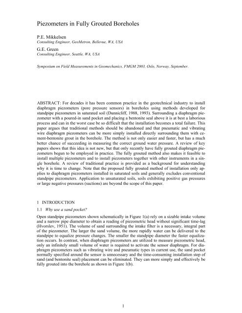
1.2 Why use a conventional bentonite seal?Proper isolation of the piezometer sensor <strong>in</strong>take along the length of the borehole is necessary <strong>in</strong>order to obta<strong>in</strong> a correct pore water pressure measurement. Seal<strong>in</strong>g a conventional standpipepiezometer can still be achieved by fully grout<strong>in</strong>g the borehole above the sand and elim<strong>in</strong>at<strong>in</strong>gthe conventional bentonite seal shown <strong>in</strong> Figure 1(a). The grout itself forms an adequate lowpermeability seal. It is common practice to place a bentonite pellet or chip seal above the sand.The bentonite is allowed to partially hydrate before tremie-grout<strong>in</strong>g the rest of the borehole.This practice should also be abandoned <strong>in</strong> order to simplify the <strong>in</strong>stallation procedure. The bentoniteseal <strong>in</strong> Figure 1(a) is redundant, but is perceived to be necessary to protect the sand frombe<strong>in</strong>g disturbed dur<strong>in</strong>g grout<strong>in</strong>g and be<strong>in</strong>g grouted. Assum<strong>in</strong>g the sand zone to be saturated,grout with a creamy consistency would penetrate the sand only a few <strong>in</strong>ches. Grout<strong>in</strong>g directlyabove the sand can be done provided excessive <strong>in</strong>itial pump pressures are avoided and the tremieis prevented from act<strong>in</strong>g like a jet nozzle directly <strong>in</strong>to the sand. Side port exits from the tremiewill prevent this. An extra few feet of sand can also help.Figure 1. (a) Open standpipe piezometer. (b) Diaphragm piezometer2 BACKGROUND2.1 Forgotten test resultsIn 1961 Penman demonstrated the vast difference <strong>in</strong> response times between open standpipe,tw<strong>in</strong>-tube hydraulic and diaphragm type piezometers. Various piezometers were pressed <strong>in</strong>to reconstitutedLondon clay with a permeability of 3.4x10 -8 cm/sec, essentially the same as bentoniteclay. Theoretical and experimental results showed how little time was required to equilibratediaphragm sensors dur<strong>in</strong>g 20 and 30 psi load<strong>in</strong>g steps and that they responded <strong>in</strong> a matterof m<strong>in</strong>utes or less (Penman, 1961). The significance of this paper has been largely overlookedwith respect to piezometer <strong>in</strong>stallation <strong>in</strong> boreholes. Whereas push<strong>in</strong>g or embedd<strong>in</strong>g piezometersdirectly <strong>in</strong>to compacted or soft clay without a sand-pocket is an accepted procedure, a boreholepiezometer is not normally <strong>in</strong>stalled without a substantial volume of sand around it. Currentworldwide practice for <strong>in</strong>stall<strong>in</strong>g standpipes and diaphragm piezometers are essentially identical.Penman’s 1961 paper demonstrates that diaphragm sensors are clearly different from openstandpipes and tw<strong>in</strong>-tube hydraulic piezometers. His studies demonstrated that a vibrat<strong>in</strong>g wirepiezometer responds extremely rapidly if embedded directly <strong>in</strong> a clay material similar to bentonite.Surround<strong>in</strong>g a diaphragm piezometer <strong>in</strong> the borehole with a cement-bentonite grout with asimilar low permeability is sound eng<strong>in</strong>eer<strong>in</strong>g.2
2.2 Ignored theoryA diaphragm piezometer embedded directly <strong>in</strong> a low permeability saturated clay strata or a largemass of low permeability cement-bentonite grout should respond <strong>in</strong>stantly to a pore water pressurechange. Effective stress pr<strong>in</strong>ciples and consolidation theory are well understood and accepted<strong>in</strong> long-stand<strong>in</strong>g soil mechanics practice. A saturated clay layer <strong>in</strong>itially responds to anapplied stress <strong>in</strong>crement, ∆σ, by an <strong>in</strong>crease <strong>in</strong> pore water pressure, ∆u = ∆σ throughout thelayer. Unfortunately the application of these pr<strong>in</strong>ciples to diaphragm piezometer equalizationand appropriate <strong>in</strong>stallation details has been largely ignored.With the aid of Darcy’s Law, Vaughan (1969, 1973) established that for very small diameterstandpipe piezometers the grouted section of the borehole can have a permeability greater thanone or even two orders of magnitude higher than the surround<strong>in</strong>g formation without degrad<strong>in</strong>gthe measured pore water pressure. This is particularly significant <strong>in</strong> fat clays with a permeabilityof 10 –8 cm/sec or less. Use of a higher permeability borehole seal is possible because of themuch higher horizontal hydraulic gradients adjacent to the piezometer than the vertical gradientsalong the grouted borehole. As illustrated <strong>in</strong> Figure 2, radial pressure gradients from the boreholewall to the piezometer are normally one to several orders of magnitude greater than thoseproduced vertically from the sensor to some po<strong>in</strong>t many feet above <strong>in</strong> another strata (R d
are mixed first, the water-cement ratio stays fixed and the strength/modulus of the set grout ismore predictable. If bentonite slurry is mixed first, the water-cement ratio cannot be controlledbecause the addition of cement must stop when the slurry thickens to a consistency that is stillpumpable.Mak<strong>in</strong>g cement-bentonite grout <strong>in</strong> the field is a straightforward process. The most effectivemix<strong>in</strong>g is commonly done <strong>in</strong> a barrel or tub with the drill-rig pump, circulat<strong>in</strong>g the batchthrough the pump <strong>in</strong> 50 to 200 gallon quantities. The rig pump provides the k<strong>in</strong>d of jet-mix<strong>in</strong>grequired to get the job done quickly. Any k<strong>in</strong>d of bentonite powder used to make drill<strong>in</strong>g mudcomb<strong>in</strong>ed with Type 1 or 2 Portland cement and water can be used, but the appropriate quantityof bentonite will vary somewhat depend<strong>in</strong>g on grade of bentonite, mix<strong>in</strong>g sequence, mix<strong>in</strong>g effort(agitation), water pH and temperature.Grout mixes should be controlled by weight and proportioned to give the desired strength ofthe set grout. The conversion factors conta<strong>in</strong>ed <strong>in</strong> Appendix H.10 <strong>in</strong> Dunnicliff (1988, 1993)are very helpful <strong>in</strong> mix design. Two mixes are given <strong>in</strong> Table 1 that varies <strong>in</strong> 28-day strengthfrom 50 psi to 4 psi for water-cement ratios of 2.5 to 6.6 respectively.Table 1. Cement-bentonite grout, water and cement mixed first.Application Grout for Medium to Hard Soils Grout for Soft SoilsMaterials Weight Ratio by Weight Weight Ratio by WeightWater 30 gallons 2.5 75 gallons 6.6Portland94 lbs.94 lbs.1Cement( 1 sack)( 1 sack)1Bentonite25 lbs.39 lbs.0.3(as required)(as required)0.4NotesThe 28-day compressive strength of this mix isabout 50 psi, similar to very stiff to hard clay. Themodulus is about 10,000 psi.The 28-day strength of this mix is about 4 psi,similar to very soft clay.3.4 Example mix<strong>in</strong>g procedure.A rig pump with one suction hose and a return hose fitted with a jet nozzle <strong>in</strong> a 50-gallon barrelare the m<strong>in</strong>imum requirements for circulation batch mix<strong>in</strong>g of grout. Paddle or high shear mixerscan also be used. A measured quantity of clean water goes <strong>in</strong>to the mix<strong>in</strong>g tub/barrel firstand pump<strong>in</strong>g and circulation starts. Then the cement is gradually added to the water and mixedthoroughly. At this stage the mix is like gray water. Next, bentonite powder is slowly added <strong>in</strong>tothe jett<strong>in</strong>g area of the barrel, slowly enough so clumps of bentonite do not form. This should beconstantly checked by scrap<strong>in</strong>g the bottom with a shovel. When clumps form, slow down and donot add any more powder until they are dissolved. Keep add<strong>in</strong>g bentonite until the watery mixtransitions to an oily/slimy consistency. Observe the consistency while mix<strong>in</strong>g and let the groutthicken for another five to ten m<strong>in</strong>utes. Generally, the mix thickens some more with addedmix<strong>in</strong>g time. Add more bentonite as required. When it is smooth and like thick cream or pancakebatter, it is as heavy as is it feasible to pump. Drips of the grout should then barely comeoff a dipped f<strong>in</strong>ger and form “craters” <strong>in</strong> the fluid surface. That is the correct consistency forpump<strong>in</strong>g the grout batch down the tremie-pipe. When possible, withdraw the tremie after eachbatch an amount correspond<strong>in</strong>g to the grout level <strong>in</strong> the bor<strong>in</strong>g to keep the pump<strong>in</strong>g pressures aslow as possible. When pump<strong>in</strong>g grout 100 feet or more from the borehole, th<strong>in</strong>ner consistencywould be required, but at the risk of some bleed<strong>in</strong>g.Old habits die hard, so that some users will <strong>in</strong>sist on mix<strong>in</strong>g water and bentonite powder firstas recommended by Dunnicliff (1988, 1993). This practice should be abandoned for <strong>in</strong>strumentgrouts. This is normally the way drill<strong>in</strong>g mud is mixed and it yields more slurry per sack ofbentonite than the above method. Also, use of hydrated bentonite with cement added last iscommon practice <strong>in</strong> grout<strong>in</strong>g technology for ground improvement. Such mixes are highly thixo5
tropic and rely on <strong>in</strong>dustrial type mix<strong>in</strong>g plants and methods. The cement content is difficult tocontrol under ord<strong>in</strong>ary field <strong>in</strong>strumentation <strong>in</strong>stallation circumstances.The amount of bentonite that is required for the above mix<strong>in</strong>g procedure will vary due tofactors mentioned earlier. The amount of bentonite shown <strong>in</strong> Table 1 should only be used as aguide and is also handy for estimat<strong>in</strong>g material quantities shipped to the site. With this methodmore bentonite is required than if water and bentonite was mixed first. This is an advantagefrom the standpo<strong>in</strong>t of want<strong>in</strong>g a low permeability. When the bentonite solids content <strong>in</strong>creases,the density <strong>in</strong>creases and the permeability is lowered. It is another reason for mix<strong>in</strong>g water andcement before add<strong>in</strong>g cement. A lower permeability is generally preferred s<strong>in</strong>ce cementbentoniteshave a higher permeability than high-density bentonite grout or chip seals.4 DIAPHRAGM PIEZOMETERS IN FULLY GROUTED BOREHOLES4.1 Recent experienceIncreas<strong>in</strong>gly, both s<strong>in</strong>gle and multiple vibrat<strong>in</strong>g wire and pneumatic pressure sensors are be<strong>in</strong>gsuccessfully grouted directly <strong>in</strong>to boreholes without sand pockets and bentonite seals. The ideais not new. Thirty years ago, Vaughan <strong>in</strong> London demonstrated that even grouted multiplesmall-diameter standpipes <strong>in</strong> clay were feasible (Vaughan, 1969). Tofani (2000) has used theprocedure for 20 years <strong>in</strong> California for both pneumatic and vibrat<strong>in</strong>g wire piezometers.McKenna (1995) <strong>in</strong> Canada has adopted the fully grouted <strong>in</strong>stallation of piezometer sensorsfollow<strong>in</strong>g extensive field test<strong>in</strong>g and McKenna and others (1994) adopted comb<strong>in</strong>ed <strong>in</strong>cl<strong>in</strong>ometercas<strong>in</strong>g and diaphragm piezometers directly grouted <strong>in</strong>to the same borehole as standard procedures.The US Army Corps of Eng<strong>in</strong>eers, Omaha District adopted fully-grouted vibrat<strong>in</strong>g wirepiezometer <strong>in</strong>stallations and <strong>in</strong>cluded them with deep <strong>in</strong>cl<strong>in</strong>ometer cas<strong>in</strong>g <strong>in</strong>stallations based onrecommendations by the first author (USACE, 1999). But, because the geotechnical communityseems to be so rooted <strong>in</strong> traditional th<strong>in</strong>k<strong>in</strong>g when it comes to seal<strong>in</strong>g a piezometer <strong>in</strong> a borehole,it is counter-<strong>in</strong>tuitive to most eng<strong>in</strong>eers to simply grout the sensors <strong>in</strong> the bor<strong>in</strong>g.Grout is perceived as a sealant that would prevent the sensor from register<strong>in</strong>g the correct porepressure, should it get between the soil and the porous element on the piezometer tip. However,based on research 40 years ago (Penman, 1961), that perception is <strong>in</strong>correct. Despite research <strong>in</strong>the 1960s that recognizes the feasibility of direct grout<strong>in</strong>g, it rema<strong>in</strong>ed largely unrecognized <strong>in</strong>1988 when the “redbook” was first published (Dunnicliff, 1988).4.2 Grout permeabilityCement-bentonite grout is a porous solid with a permeability that lies somewhere <strong>in</strong> the cementand bentonite range mentioned above. Typical published values of permeability are listed <strong>in</strong> Table2. Vaughan (1973) quotes a coefficient of permeability for a pumpable cement-bentonitegrout mix on the order of 5x10 -8 cm/sec. For low bentonite solid contents the permeability canbe expected to be close to 10 -6 cm/sec and for higher bentonite solids content it would be closeto 10 -8 cm/sec. So the issue is really not if this method works, but how well does it work andwhat, if any, are the limitations <strong>in</strong>volved with the use of vibrat<strong>in</strong>g wire sensors or pneumaticsensors.Table 2. Permeability, k, of some grouts.Grout Type Characteristics k (cm/sec) SourceNeat cement w/c ratio = 0.89 to 0.53 10 -5 to 10 -7 BaroidBentonite chips hydrated 10 -8 BaroidBentonite slurry 6 % solids 10 -5 BaroidBentonite slurry 20 % solids 10 -8 BaroidCement-bentonite water/solids = 4 to 1 10 -6 Vaughan, 1969Cement-bentonite w : c : b = 4 : 1 : 1 5 x 10 -8 Vaughan, 19736
4.3 Vibrat<strong>in</strong>g wire vs. pneumatic piezometersResponse tests (Penman, 1961; Tofani, 2000; McKenna, 1995; Mikkelsen and Slope IndicatorCo., 2000) all show that both vibrat<strong>in</strong>g wire and pneumatic sensors stabilize after a pressurechange <strong>in</strong> a matter of seconds to several m<strong>in</strong>utes. Examples of recent response test<strong>in</strong>g on a vibrat<strong>in</strong>gwire piezometer embedded <strong>in</strong> cement-bentonite grout are shown <strong>in</strong> Figures 4 and 5(Mikkelsen and Slope Indicator Co., 2000). However, it should be recognized that vibrat<strong>in</strong>gwire and other electrical sensors have an advantage over pneumatic sensors. The volume of fluiddisplaced at a vibrat<strong>in</strong>g wire diaphragm dur<strong>in</strong>g a pressure change is extremely small, so thatsystem equilibrium is rapid. Dur<strong>in</strong>g read<strong>in</strong>g, no actual displacement of the diaphragm occurs. Incontrast, the diaphragm of a pneumatic sensor has to displace a small amount of pore-fluid everytime the sensor is activated to take a read<strong>in</strong>g. Experience demonstrates that a small amount ofundisolved air must be present <strong>in</strong> the <strong>in</strong>take area of the sensor for it to work properly <strong>in</strong> lowpermeability clay. A fully saturated pneumatic sensor embedded <strong>in</strong> clay must overcome the totalsoil pressure for <strong>in</strong>itial movement of the diaphragm. Obta<strong>in</strong><strong>in</strong>g a stable, reliable pore water pressureread<strong>in</strong>g is not only time-consum<strong>in</strong>g, but also often nearly impossible to get. A pneumaticpiezometer should be <strong>in</strong>stalled without any special effort to remove all the air outside the diaphragm.It is a necessary compromise with an obvious sacrifice <strong>in</strong> response <strong>in</strong> low permeabilityclay. In contrast, a vibrat<strong>in</strong>g wire piezometer should be <strong>in</strong>stalled upside down, fastened to its cableand flooded with water to discourage air from collect<strong>in</strong>g aga<strong>in</strong>st the diaphragm.4035Pressure Head <strong>in</strong> Feet302520151050Piezom eterCham ber0 2 4 6 8 10 12 14 16 18 20Elapsed Time <strong>in</strong> M<strong>in</strong>utesFigure 4. Vibrat<strong>in</strong>g wire piezometer response after 288 days cure. Piezometer embedded under 200 mmof cement-bentonite grout <strong>in</strong>side chamber. Pressure applied above grout surface and piezometer responserecorded.4Response Time <strong>in</strong> M<strong>in</strong>utes32150%90%95%99.9%00 30 60 90 120 150 180 210 240 270 300C u r<strong>in</strong> g T im e <strong>in</strong> D a y sFigure 5. Vibrat<strong>in</strong>g wire piezometer response time vs. grout cur<strong>in</strong>g time.As a practical matter, lower<strong>in</strong>g a diaphragm piezometer down a water or mud-filled boreholeusually requires added weight to keep the cable or tube straight and counteract buoyancy andborehole stick<strong>in</strong>ess. A short length of re-bar can be attached. A better method, especially for thepneumatic sensors, is to enclose the sensor <strong>in</strong> a 1.5 to 2-<strong>in</strong>ch diameter, sand-filled geo-textile (or7
canvas) sock. This will encourage entrapment of a small amount of free air. Diaphragm piezometerscan be directly attached to <strong>in</strong>cl<strong>in</strong>ometer cas<strong>in</strong>g dur<strong>in</strong>g assembly without the re-bar orthe sand-filled sock. As a f<strong>in</strong>al note, pneumatic piezometers are generally unsuitable for measur<strong>in</strong>gnegative (sub-atmospheric) pressure whereas the vibrat<strong>in</strong>g wire piezometers are quite capableof measurements to 7 psi (50 kPa) below ambient atmospheric pressure.4.4 Cement-bentonite as a high air-entry filterAs a side issue, the cement-bentonite grout discussed here<strong>in</strong> also offers advantages of <strong>in</strong>terestfor pore water suction measurements <strong>in</strong> partially saturated soils. Dur<strong>in</strong>g the preparation of thisarticle it was po<strong>in</strong>ted out (Vaughan, 2001) that cement-based grouts have an air entry value upto about 100 psi, a property required for measurement of negative pore pressures. The grout,when set, becomes a perfectly saturated porous material, a far easier task than pre-saturat<strong>in</strong>g ahigh-air entry ceramic filter and deploy<strong>in</strong>g it down a borehole. A vibrat<strong>in</strong>g wire piezometer fullygrouted with<strong>in</strong> cement-bentonite grout can therefore be expected to measure negative pore waterpressure or suction. Research is currently <strong>in</strong> progress <strong>in</strong> the UK on the role of grouts surround<strong>in</strong>gdirectly grouted-<strong>in</strong> piezometer tips designed to measure suction and the air entry value ofgrouts.5 MULTIPLE PIEZOMETERS IN A BOREHOLE5.1 Simplicity and reduced costThe borehole is the highest cost component of an <strong>in</strong>strument <strong>in</strong>stallation, so that there is a great<strong>in</strong>centive to put more than one sensor or more <strong>in</strong>strument types for that matter, <strong>in</strong> the sameborehole. Debate has surrounded this topic <strong>in</strong> the past, because of the perceived lack of ability toseal around multiple cables, pipes and tubes <strong>in</strong> one bor<strong>in</strong>g. It is the author’s op<strong>in</strong>ion that mostdifficulties arise from deal<strong>in</strong>g with rigid standpipes and attempt<strong>in</strong>g to place multiplesand/bentonite seals. Elim<strong>in</strong>ation of multiple rigid pipes, poured-<strong>in</strong> sand-pockets, bentonite layersand opportunity for multiple down-hole measurements, are considerable benefits.The ability to reliably <strong>in</strong>stall two, three or more piezometers <strong>in</strong> one borehole has enormousattractions. Vibrat<strong>in</strong>g wire piezometer sensors <strong>in</strong> fully grouted boreholes practically elim<strong>in</strong>atesthe risk of <strong>in</strong>stallation failure. The sensors should probably be spaced no closer than 10 to 20feet apart. An option exists for users who rema<strong>in</strong> skeptical about <strong>in</strong>troduc<strong>in</strong>g grout between thesoil and the porous piezometer filter. An enlarged porous pad directly attached to the piezometersensor can be pressed directly aga<strong>in</strong>st the borehole wall by spr<strong>in</strong>gs (Green, 2000). Mechanicaland hydraulic jacks have been used <strong>in</strong> Norway to achieve direct contact and a spr<strong>in</strong>g-actuatedsystem was used successfully on a very deep <strong>in</strong>stallation <strong>in</strong> Canada. Pneumatically releasedspr<strong>in</strong>g-loaded multi-level piezometers are now available from Geokon for <strong>in</strong>stallation <strong>in</strong> fullygrouted boreholes. Whether or not the spr<strong>in</strong>g-actuated system is used should not detract fromthe data quality; its use may encourage skeptics to go fully grouted.5.2 Installation methodsA number of basic <strong>in</strong>stallation methods can be successfully employed depend<strong>in</strong>g on drill<strong>in</strong>gmethod, borehole stability and user preferences. Variations <strong>in</strong> these methods may be appropriate.• Install piezometers one by one from bottom up <strong>in</strong> an open borehole. Grout and withdrawtremie pipe as grout<strong>in</strong>g proceeds. Alternatively, attach piezometers to rigid tremie pipe andleave tremie pipe <strong>in</strong> place.• Install piezometers one by one from the bottom up <strong>in</strong>side cas<strong>in</strong>g or hollow stem auger. Attachpiezometers to rigid tremie pipe and leave <strong>in</strong> place while pull<strong>in</strong>g cas<strong>in</strong>g or auger.8
• Drill and grout hole and pull cas<strong>in</strong>g and auger. Install one by one from bottom up <strong>in</strong> groutfilled hole. Add weight to each piezometer as required to overcome viscous resistance whilelower<strong>in</strong>g piezometer.• Attach directly to outside of <strong>in</strong>cl<strong>in</strong>ometer cas<strong>in</strong>g midway between cas<strong>in</strong>g coupl<strong>in</strong>gs.• Attach directly to outside of corrugated polyethylene pipe (Sondex) or similarly attach tomagnet/reed switch cas<strong>in</strong>g between magnet sensors so that pore water pressure and settlementare measured along the same borehole.• Build a series of vibrat<strong>in</strong>g wire piezometers <strong>in</strong>to a coupled 2-<strong>in</strong>ch PVC pipe so that piezometersand cables are <strong>in</strong>side the PVC pipe, Figure 6. Useful <strong>in</strong> deep <strong>in</strong>stallations <strong>in</strong>sidecas<strong>in</strong>g or augers to prevent cable damage dur<strong>in</strong>g cas<strong>in</strong>g or auger rotation dur<strong>in</strong>g extraction.Tremie-grout outside the PVC pipe. Telescop<strong>in</strong>g coupl<strong>in</strong>gs may be <strong>in</strong>serted to accommodatesettlement.Figure 6. Multi-level piezometers <strong>in</strong> PVC pipe.6 CONCLUSIONS• Theoretically, fully grouted diaphragm piezometers should correctly measure the pore waterpressure <strong>in</strong> the surround<strong>in</strong>g saturated soil. Effective stress concepts are well established andDarcy’s Law helps us understand the significance of how the larger radial pressure gradientat a particular piezometer governs the measured pressure and that the smaller pressure gradientsalong a grouted borehole severely limits the effect of leakage along the borehole.• Empirical evidence from Penman (1961) and Vaughan (1969), and more recently byMcKenna (1995), Tofani (2000) and the first author, clearly demonstrate that grouted-<strong>in</strong>diaphragm piezometers should and do work reliably. It is time for fully grouted diaphragmpiezometers to be adopted <strong>in</strong> general without further delay or pend<strong>in</strong>g further test<strong>in</strong>g.• A cement-bentonite grout mixture is the most reliable, versatile, easily mixed and readilypumpable grout for piezometer grout<strong>in</strong>g seals. Poured <strong>in</strong> place sand pockets placed aroundthe piezometer tip and sealed with compressed bentonite pellets or granular bentonite shouldbe abandoned. S<strong>in</strong>gle component bentonite seal<strong>in</strong>g grouts are too difficult to control dur<strong>in</strong>gmix<strong>in</strong>g, may set up too quickly and if th<strong>in</strong>ned may rema<strong>in</strong> too soft when set.• A fully grouted diaphragm piezometer is simpler and easier to <strong>in</strong>stall and therefore is morereliable. It saves considerable field <strong>in</strong>stallation time and is less costly.• <strong>Fully</strong> grouted <strong>in</strong>stallations facilitate plac<strong>in</strong>g multi-level piezometers <strong>in</strong> a s<strong>in</strong>gle borehole andprovide great sav<strong>in</strong>gs <strong>in</strong> drill<strong>in</strong>g and <strong>in</strong>strument <strong>in</strong>stallation cost. They are much simpler andless costly than other multi-level piezometer systems available (e.g. Westbay and Waterloo).9
• Multi-level piezometer <strong>in</strong>stallations provide more details of pore water pressure/depth profiles<strong>in</strong> complex strata with irregular ground water regimes, often reveal<strong>in</strong>g unrecognizedpotential failure mechanisms or expla<strong>in</strong><strong>in</strong>g previously unexpla<strong>in</strong>ed field behavior.• <strong>Fully</strong> grouted <strong>in</strong>stallations open up the opportunity to place multiple <strong>in</strong>strument types <strong>in</strong> as<strong>in</strong>gle borehole, e.g. <strong>in</strong>cl<strong>in</strong>ometers and piezometers.REFERENCESDunnicliff, J. 1988, 1993. Geotechnical Instrumentation for Measur<strong>in</strong>g Field Performance, New York, J.Wiley.Green, G.E. 2000. Geotechnical Field Instrumentation: What’s New <strong>in</strong> 2000. Geotechnical News, Vol.18,No. 4, Dec.: 26-30.Hvorslev, M.J. 1951. Time Lag and Soil Permeability <strong>in</strong> Groundwater Observations. Bullet<strong>in</strong> No. 36, U.S.Waterways Experiment Station, Vicksburg, MI.Marsland, A. 1973. Discussion, Pr<strong>in</strong>ciples of Measurement. In Field Instrumentation <strong>in</strong> Geotechnical Eng<strong>in</strong>eer<strong>in</strong>g:531-532. British Geotechnical Society, London: Halsted Press a Division of John Wiley.McKenna, G.T. 1995. <strong>Grouted</strong>-In Installation of <strong>Piezometers</strong> <strong>in</strong> <strong>Boreholes</strong>. Canadian Geotechnical Journal,Vol. 32: 355-363.McKenna, G.T., Liv<strong>in</strong>gstone, G. and Lord, T. 1994. Advances <strong>in</strong> Slope-Monitor<strong>in</strong>g Instrumentation atSyncrude Canada Ltd. Geotechnical News, Vol. 12, No.3, Sept.: 69.Mikkelsen, P.E. and Slope Indicator Co. 2000. Grout<strong>in</strong>g-<strong>in</strong> <strong>Piezometers</strong>. In Technical Note atwww.slope.com, 2 pages.Mikkelsen, P.E. 2002. Cement-Bentonite Grout Backfill for Borehole Instruments. Geotechnical News,Vol.20, No.4, December: 38-42.Penman, A.D.M. 1961. A Study of the Response Time of Various Types of <strong>Piezometers</strong>. In Pore Pressureand Suction <strong>in</strong> Soils. British Geotechnical Society: 53–58. London: Butterworths.Tofani, G.D. 2000. Grout In-Place Installation of Slope Incl<strong>in</strong>ometers and <strong>Piezometers</strong>. In Sem<strong>in</strong>ar onGeotechnical Field Instrumentation at University of Wash<strong>in</strong>gton, Am. Society of Civil Eng<strong>in</strong>eers SeattleSection, Geotechnical Group, Seattle: ASCE.US Army Corps of Eng<strong>in</strong>eers 1999. Dam Safety Major Rehabilitation, Phase 1, Oahe Dam, Pierre, SouthDakota. Omaha, NE, October.Vaughan, P.R. 1969. A Note on Seal<strong>in</strong>g <strong>Piezometers</strong> <strong>in</strong> <strong>Boreholes</strong>. Geotechnique, Vol. 19, No. 3, 405-413.Vaughan, P.R. 1973. Discussion, Pr<strong>in</strong>ciples of Measurement. In Field Instrumentation <strong>in</strong> GeotechnicalEng<strong>in</strong>eer<strong>in</strong>g: 542-543. British Geotechnical Society, London: Halsted Press a Division of John Wiley.Vaughan, P. R. 2001. Personal communication.10


