B.1 General Modeling ApproachFor this report, a steady-state conduction model was used. Air cavities were assumed to havean effective thermal conductivity which includes the effects <strong>of</strong> cavity convection. Interior/exteriorair films were taken from Table 1, p. 26.1 <strong>of</strong> 2009 ASHRAE Handbook – Fundamentsdepending on surface orientation. From the calibration in 1365-RP, contact resistances betweenmaterials were modeled. The temperature difference between interior and exterior was modeledas a dimensionless temperature index between 0 and 1 (see Appendix B.3). These values,along with other modeling parameters, are given in ASHRAE 1365-RP, Chapter 5.B.2 <strong>Thermal</strong> TransmittanceThe methodology presented in ASHRAE 1365-RP separates the thermal performance <strong>of</strong>assemblies and details in order to simplify heat loss calculations. For the assemblies, acharacteristic area is modeled and the heat flow through that area is found. To find the effects <strong>of</strong>thermal bridges in details (such as slab edges), the assembly is modeled with and without thedetail. The difference in heat loss between the two models is then prescribed to that detail. Thisallows the thermal transmittances to be divided into three categories: clear field, linear and pointtransmittances.The clear field transmittance is the heat flow from the wall or ro<strong>of</strong> assembly, including uniformlydistributed thermal bridges that are not practical to account for on an individual basis, such asstructural framing, brick ties and cladding supports. This is treated the same as in standardpractice, defined as a U-value, Uo (heat flow per area). For a specific area <strong>of</strong> opaque wall, thiscan be converted into an overall heat flow per temperature difference, Qo.The linear transmittance is the additional heat flow caused by details that can be defined by acharacteristic length, L. This includes slab edges, corners, parapets, and transitions betweenassemblies. The linear transmittance is a heat flow per length, and is represented by psi (Ψ).The point transmittance is the heat flow caused by thermal bridges that occur only at single,infrequent locations. This includes building components such as pipe penetrations andintersections between linear details. The point transmittance is a single additive amount <strong>of</strong> heat,represented by chi (χ).With these thermal quantities the overall heat flow can be found simple by adding all thecomponents together, as given in equation 1.thermalbri dgeoL QoQ Q Q EQ 1Equation 1 gives the overall heat flow for a given building size. For energy modeling, orcomparisons to standards and codes, <strong>of</strong>ten it is more useful to present equation 1 as a heat flowper area. Knowing that the opaque wall area is A total , and U=Q/At otal , equation 2 can be derived.U L ATotalUoEQ 2
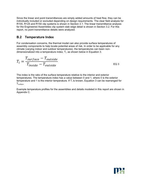
Since the linear and point transmittances are simply added amounts <strong>of</strong> heat flow, they can beindividually included or excluded depending on design requirements. The clear field analysis forR100, R125 and R150 clip systems is shown in Section 3.1. The linear transmittance analysisfor the <strong>Engineered</strong> <strong>Assemblies</strong> clip system slab edge detail is shown in Section 3.2. For thisreport, no point transmittance details were analyzed.B.2 Temperature IndexFor condensation concerns, the thermal model can also provide surface temperatures <strong>of</strong>assembly components to help locate potential areas <strong>of</strong> risk. In order to be applicable for anyclimate (varying indoor and outdoor temperatures), the temperatures can been nondimensionalizedinto a temperature index, T i , as shown below in Equation 3.EQ 3The index is the ratio <strong>of</strong> the surface temperature relative to the interior and exteriortemperatures. The temperature index has a value between 0 and 1, where 0 is the exteriortemperature and 1 is the interior temperature. If T i is known, Equation 3 can be rearranged forT surface .Example temperature pr<strong>of</strong>iles for the assemblies and details modeled in this report are shown inAppendix C.