Why does Fibre Cement Matter? - ENGINEERED ASSEMBLIES
Why does Fibre Cement Matter? - ENGINEERED ASSEMBLIES
Why does Fibre Cement Matter? - ENGINEERED ASSEMBLIES

You also want an ePaper? Increase the reach of your titles
YUMPU automatically turns print PDFs into web optimized ePapers that Google loves.
Table of summary statistics for distribution, please contact EA 9 at 905 816 2218
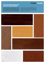
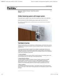
High Density vs. Medium Density We consider fibre cement products with a density of 1650 gr/m³ or more to be high density. Medium density fibre cement, which means it has less density than High density cladding panels, has been developed for the residential marketplace, the most common of those being Hardipanel. The difference is in durability, resistance to water that can cause cyclical freeze thaw failure, dimensional tolerance and other factors that affect longterm performance and design freedom. Because of these properties; • Medium density panels can’t be used in high rise buildings • Medium density panels need to be coated, on both sides • Medium density panels need more supporting structure, for example on one recent job the girt and fastener spacing with medium density panels was 16” on centre, while in high density fastener and girt spacing are typically 24”. That is why the majority of uses are for residential applications. One might ask why residential buildings can accept less quality products when they must last as long as any institutional building. Surfaces and colours The natural, untreated surface of fibre cement is velvety and open-‐pored. Products for external use are coated or treated with a hydrophobic coating so that efflorescence and dirt do not become a problem. The rear side is treated in a similar way to balance the forces. <strong>Fibre</strong> cement surfaces are smooth, sanded or textured. The most used panels are smooth. Innovation occurs in the colour availability, the thru coloured aspect combined with a pigmented transparent top-‐coating. Some manufacturers even provide an extra anti-‐graffiti layer! Colours can provide the cement look, or be a fully covering surface coating. Colour-‐thru panels are created by including pigments, in the cement slurry, during manufacturing. They provide colour while maintaining the natural cement aesthetic. Some panels can have slight irregularities and imperfections that allow the wall to have some variability. This is desired in order to give the wall some ‘life’. If a more homogeneous look is desired, panels are available that have a coating that makes the panels identical. Colour fastness or durability is dependent upon the manufacturer and the choice of pigments. Dark colours can fade, and some manufacturers design with this in mind. Others have spent research and development to reduce fading and differentiate their products by their colour durability. This can be measured by objective tests. Freeze thaw testing of EN 12467 for distribution, please contact EA 10 at 905 816 2218
Canadian climates possibly impact buildings as bad as any place on earth. The temperature cycling through the freezing point is a key driver of this impact. <strong>Fibre</strong> <strong>Cement</strong> is used in many geographies that have similar climate as Canada, as well has been used in Canada for many decades. In the EN 12467 testing, product is tested for 100 cycles of freeze thaw. The testing roughly works by putting the panel through in water, conditioning the material to be soaked. Then the panel is put through 100 cycles of freezing and thawing. Then it is subjected to the bending test. Class A products pass this test. It is interesting to note that Class B products only pass 25 cycles. Class B products may be medium density panels. for distribution, please contact EA 11 at 905 816 2218
History and Manufacturing Process (more info that you may need to know ) The manufacturing process for Eternit <strong>Fibre</strong> <strong>Cement</strong> has been the same for 100 years. Only the process has been fine tuned and some ingredients have changed. Some other types of materials are made as thin versions of precast, just formed and cured. This is something much more special which has not been replicated in other manners. The Hatschek machine was first developed for the production of asbestos cement in the 1890’s, when it was patented by the inventor, Ludwig Hatschek. The machine is still used in the same basic form today and although modern Hatschek machines are much more productive than the early models they would still be recognised by the inventor if he were alive today. Figure 1: Schematic of Hatschek Machine showing principal components. The fundamental part of the Hatschek machine consists of a vat in which a cylindrical sieve rotates in contact with a dilute water based slurry of fibres capable of forming a filtering film and mineral materials including Portland cement. (Figure 1) The sieve cylinder is mounted on an axle and driven by a continuous felt wrapped around the top of the sieve by a couch roller. The felt is threaded around a drive or anvil roller and a tail roller. The drive or anvil roller is pushed into hard contact with an accumulation roller. Sheets are formed on the Hatschek machine as follows. 1. As the clean sieve is pulled under the slurry in the vat, water from the slurry runs through the sieve depositing a soft porous film of fibres and cement on the surface of the sieve. 2. The sieve carrying the film exiting the vat is brought into contact with the felt stretched tightly across the sieve. This removes much of the water from the film by forcing it back through the film. The solid film floats on this layer of water and is transferred to the felt partly in response to the effect of removal of water and partly because the felt has a greater affinity for the film than the sieve. (Figure 2) for distribution, please contact EA 12 at 905 816 2218
3. The film is carried on the felt to an accumulator roll to which it is transferred by further removal of water at high pressure. 4. A sufficient number of films are wrapped on the accumulator roll to form a sheet of the desired thickness; the stack of films is then removed from the roller and laid out flat to form the sheet. The action of dewatering successive films in contact with each other under pressure is sufficient to bind the films together to form a contiguous solid sheet. Materials The feed to a Hatschek machine is a slurry of fibres, Portland <strong>Cement</strong> and finely ground minerals in water. <strong>Fibre</strong>s: Asbestos fibres were used in the original formulations and indeed asbestos containing fibre cement is still made today. In later times asbestos was supplemented and more recently has been totally replaced with cellulose fibres and PVA fibres of various kinds. It is also common to use various synthetic fibres capable of providing specific properties to the final product. In this paper we will concentrate on modern cellulose based composites as these are of more abiding interest. Cellulose fibres may be up to 4 mm in length depending on the wood species used. The commonly used wood fibres are less than 3 mm. Cellulose fibres may vary in diameter but their diameter variation is small from species to species is typically around 40 μm. No matter what is the source of the fibres, filter film formation is dependent on their hydraulic properties. for distribution, please contact EA 13 at 905 816 2218
Non Fibrous Materials: The specific materials used in addition to Portland <strong>Cement</strong> in modern fibre cement depend on the properties intended in the final product. There are two main categories of cellulose fibre cement -‐ low temperature cured (commonly known as air cured) and high temperature or autoclave cured. Air cured formulations will usually contain large amounts of Portland cement combined with very finely divided materials such as clays, Silica fume, ground limestone or fly ash. Autoclaved formulations will normally contain finely ground silica with other finely ground minerals and lesser quantities of cement all. With the exception of clays and silica fume that may have particles size of 2 μm or less, non-‐fibrous materials typically average around 50 μm in diameter the same size as Portland <strong>Cement</strong>. This is important in the formation of films. Summary This is a taste of the manufacturing process. The complete report is available. As the Hatschek process has been around for some time, engineers have continued to reform and improve the process. The intent of providing some of this detail is to show that there is much more to this than preparing a cementious material and allowing it to cure. The result of this innovation is that fibre cement is a thin, light weigh, but extremely tough material for cladding purposes. Source: Formation of Films on Hatschek Machines Tony Cooke M.App.Sc, M.R.A.C.I., M.A.I.Ch.E. Building Materials and Technology Pty Ltd. Australia for distribution, please contact EA 14 at 905 816 2218
Do’s and Don’ts of RVRS There are a few things that need to be done right, and if so the system will endure a very long time. There are things that if done wrong will compromise the system. Do’s -‐-‐-‐-‐-‐-‐-‐-‐-‐-‐-‐-‐-‐-‐-‐vertical girts behind the panel spacing as per local loads, typically 600mm ( 2 ft ) on centre vertical girts attached to horizontal girts for support, or universal nailing surface like plywood EPDM liner on girts, so that panel has free surface upon which to expand and contract. breathable weather barrier at back of cavity ventilated system top and bottom of wall at a minimum including under and above windows. panels not touching, typical spacing 8mm predrilled holes, to correct spacing. See below about fixed and floating points fasteners straight (in case of typical front fastening) fasteners not too tight as per manufacturer’s instructions. Correct use of fixed and floating points as per manufacturer’s instructions. Different panels require different configurations. A fixed point is created by slightly tighter holes or the use of manufacturer recommended or supplied spacers. Floating points are created by having holes predrilled larger than the fastener. Metal vertical girts should not reach more than one floor at time, to allow for the metal expansion and contraction. A panel should not be connected to two different girts, in such a way that the girts expansion and contraction could create forces within the panel. Cut edges sealed with manufactured provided sealant. If impact is an issue, like in a school yard, support the panel more frequently. Design assistance from Engineered Assemblies can help you with experience in this condition. Cutting can be done on site with the recommended blade on a table saw. Support of the panel during cutting is important. Don’ts -‐-‐do not bind the panel to the wall so it cannot expand and contract do not but the panels up against each other for distribution, please contact EA 19 at 905 816 2218
Handling -‐-‐-‐-‐-‐Boards have to be stored fully supported on a level base. Pay attention to the bearing strength of the underground Cover the boards with a foil to protect them against humidity, direct sunburn and dirt. Never pull the boards; they have to be lifted up. Boards must be carried vertically. Think of a finish cleaning of the facade (cleaning can be done with pure water and a sponge) for distribution, please contact EA 21 at 905 816 2218
With attention to these basic do’s and don’ts the panel will last a long time, and the wall system will continue to operate as a Rear Ventilated Rain Screen. The other components of the wall system including insulation, structure etc will be continually dried out, ensuring no issues with mould and mildew, insects etc. for distribution, please contact EA 22 at 905 816 2218
Conclusion Buildings constructed from fibre cement can all look different. The design freedom of the architect is the fabulous feature of this kind of material. This brings difference, variety and life to building design in such a way that is much more difficult in other materials. And the rear ventilated rain screen wall system is a better building envelope, allowing these buildings to last a lot longer and perform for their inhabitants. Canadian architects are in a special time when these buildings are still different on the landscape. With a proven system and material they can design buildings for their clients that have greater “curb appeal” and performance simultaneously. There is no mystery on how to build with this product. It is proven. One must only follow a few simple rules and then know it is designable, buildable and sustainable. So we trust this document has answered some of the questions you might have had about this product area. We feel privileged to help. Please share any comments and feedback at info@engineeredassemblies.com or 905 816 2218. Best regards, Blair Davies, P.Eng. for distribution, please contact EA 23 at 905 816 2218