Download
Download
Download
- No tags were found...

You also want an ePaper? Increase the reach of your titles
YUMPU automatically turns print PDFs into web optimized ePapers that Google loves.
Operating Instructions –MAN Marine Diesel Engines3
PrefaceDear Customer,these Operating Instructions are intended to familiarize you with your new MAN Dieselengine and how it operates.This manual is supplemented by the publication “Fuels, Lubricants and Coolants for MANDiesel Engines” and the “Service record book”.Note:All three publications belong to the engine and must always be kept ready tohand near the engine in the engine room.Comply in full with instructions relating to operation, prevention of accidents andenvironmental protection.MAN Diesel engines are developed and manufactured in line with the latest state of theart. However, trouble-free operation and high performance can only be achieved if thespecified maintenance intervals are observed and only approved fuels, lubricants andcoolants are used.It is imperative and in your own interest to entrust your MAN Local Service Centre withthe removal of any disturbances and with the performance of checking, setting, andrepair work.Yours faithfully,MAN Nutzfahrzeuge AktiengesellschaftWerk NürnbergSubject to change to keep abreast with technological progress.© 2003 MAN Nutzfahrzeuge AktiengesellschaftNo parts of this publication may be reproduced or translated without prior written permissionof MAN. MAN explicitly reservs all rights according to copyright law.MTDA Technical status: 04.2003 51.99493–84965
InstructionsImportant instructions which concern technical safety and protection of persons are emphasisedas shown below.Danger:This refers to working and operating procedures which must be complied with inorder to rule out the risk to persons.Caution:This refers to working and operating procedures which must be complied with inorder to prevent damage to or destruction of material.Note:Explanations useful for understanding the working or operating procedure to beperformed.Fitting flat seals / gasketsFlat seals / gaskets are often inserted with sealing agents or adhesives to make fittingthem easier or to achieve better sealing. Flat seals may slip in operation due to the “sewing-machine”effect, in particular if they are used between parts with different rates of linearexpansion under heat (e.g. aluminium and cast iron), and leaks may then occur.Example:the cap of the front crankshaft seal. If a sealing agent or an adhesive is used here the flatseal will move inwards in the course of time as a result of the different expansion rates ofthe materials. Oil will be lost, for which the shaft seal may be thought to be responsible.Flat seals / gaskets can be fitted properly only if the following points are observed:D Use only genuine MAN seals / gasketsD The sealing faces must be undamaged and cleanD Do not use any sealing agent or adhesive – as an aid to fitting the seals a little greasecan be used if necessary so that the seal will stick to the part to be fittedD Tighten bolts evenly to the specified torque6
ContentsPageDeclaration . . . . . . . . . . . . . . . . . . . . . . . . . . . . . . . . . . . . . . . . . . . . . . . . . . . . . . . . . . . . . . . 8Nameplates . . . . . . . . . . . . . . . . . . . . . . . . . . . . . . . . . . . . . . . . . . . . . . . . . . . . . . . . . . . . . . . 9Safety regulations . . . . . . . . . . . . . . . . . . . . . . . . . . . . . . . . . . . . . . . . . . . . . . . . . . . . . . . . . 10Commissioning and operation . . . . . . . . . . . . . . . . . . . . . . . . . . . . . . . . . . . . . . . . . . . . . 14Engine views . . . . . . . . . . . . . . . . . . . . . . . . . . . . . . . . . . . . . . . . . . . . . . . . . . . . . . . . . . . . 14First commissioning . . . . . . . . . . . . . . . . . . . . . . . . . . . . . . . . . . . . . . . . . . . . . . . . . . . . . . 16Commissioning . . . . . . . . . . . . . . . . . . . . . . . . . . . . . . . . . . . . . . . . . . . . . . . . . . . . . . . . . . 18Starting . . . . . . . . . . . . . . . . . . . . . . . . . . . . . . . . . . . . . . . . . . . . . . . . . . . . . . . . . . . . . . . . . 19Operation monitoring . . . . . . . . . . . . . . . . . . . . . . . . . . . . . . . . . . . . . . . . . . . . . . . . . . . . . 20Shutting down . . . . . . . . . . . . . . . . . . . . . . . . . . . . . . . . . . . . . . . . . . . . . . . . . . . . . . . . . . . 49Maintenance and care . . . . . . . . . . . . . . . . . . . . . . . . . . . . . . . . . . . . . . . . . . . . . . . . . . . . . 50Lubrication system . . . . . . . . . . . . . . . . . . . . . . . . . . . . . . . . . . . . . . . . . . . . . . . . . . . . . . . 50Fuel system . . . . . . . . . . . . . . . . . . . . . . . . . . . . . . . . . . . . . . . . . . . . . . . . . . . . . . . . . . . . . 53Cooling system . . . . . . . . . . . . . . . . . . . . . . . . . . . . . . . . . . . . . . . . . . . . . . . . . . . . . . . . . . 56V-belts . . . . . . . . . . . . . . . . . . . . . . . . . . . . . . . . . . . . . . . . . . . . . . . . . . . . . . . . . . . . . . . . . . 59Alternator . . . . . . . . . . . . . . . . . . . . . . . . . . . . . . . . . . . . . . . . . . . . . . . . . . . . . . . . . . . . . . . 61Temporary decommissioning of engines . . . . . . . . . . . . . . . . . . . . . . . . . . . . . . . . . . . . 61Technical data . . . . . . . . . . . . . . . . . . . . . . . . . . . . . . . . . . . . . . . . . . . . . . . . . . . . . . . . . . . . 62Troubleshooting table . . . . . . . . . . . . . . . . . . . . . . . . . . . . . . . . . . . . . . . . . . . . . . . . . . . . . 66Index . . . . . . . . . . . . . . . . . . . . . . . . . . . . . . . . . . . . . . . . . . . . . . . . . . . . . . . . . . . . . . . . . . . . . 687
DeclarationDeclarationIn accordance with Article 4, paragraph 2, in conjunction with Appendix II, section B, ofDirective 89/392/EEC, version 93/44/EECMAN Nutzfahrzeuge Aktiengesellschaft,hereby declares that the engine described below is destined for installation in a machineas defined in the EC directive on machines.Engine model:Design:Engine number:For data see original declarationIf required this declaration isenclosed with the delivery note.Rating / speed:Note:The manufacturer of the complete ready-to-use machine in which this engine isto be installed must take the further action necessary in the context of indirectsafety-related engineering and provision of instructions to ensure that the readyto-usemachine complies with the requirements of the EC directive on machines.The engine must not be put into operation until the complete machine satisfiesthe conditions laid down in the EC directive on machines 89/392/EEC, most recentlyamended by 93/44/EEC, or the latest amendment of said directive.MAN Nutzfahrzeuge AktiengesellschaftVogelweiherstraße 33D–90441 Nürnberg8
::NameplatesIn all your correspondence please alwaysquote engine model, serial number and jobnumber (Order number).For this reason it is advisable to read off thedata from the engine type plates beforeputting the engine into operation and toenter them in the appropriate spaces.The engine type plates are on the crankcase(see illustration).ModelMAN Nutzfahrzeuge AktiengesellschaftTypMotor-Nr. / Engine No.NI/II......................................................................delivered on......................................................................installed on......................................................................Engine serial number......................................................................Order number......................................................................MAN Nutzfahrzeuge AktiengesellschaftWerk Nürnberg Germany:Bauj.YearTypModelMotor–Nr.Serial NoWerk–Nr.Job No Leistung kW Rating kW Drehz. 1/min Speed rpmTemp. ° CLeistg. PSRating BHPAufstellhohe m uNN Altitude m–02199
Safety regulationsGeneral notesHandling diesel engines and the necessary resources is no problem when the personnelcommissioned with operation and maintenance are trained accordinglyand use their common sense.This summary is a compilation of the most important regulations. These are broken downinto main sections which contain the information necessary for preventing injury to persons,damage to property and pollution. In addition to these regulations those dictated bythe type of engine and its site are to be observed also.Important:If, despite all precautions, an accident occurs, in particular through contact with causticacids, fuel penetrating the skin, scalding from hot oil, anti-freeze being splashed in theeyes etc., consult a doctor immediately.1. Regulations designed to prevent accidents with injury to personsDuring commissioning, starting and operationD Before putting the engine into operation for the first time, read the operatinginstructions carefully and familiarize yourself with the “critical”points. If you are unsure, ask your MAN representative.D For reasons of safety we recommend you attach a notice to the door ofthe engine room prohibiting the access of unauthorized persons and thatyou draw the attention of the operating personal to the fact that they areresponsible for the safety of persons who enter the engine room.D The engine must be started and operated only by authorized personnel.Ensure that the engine cannot be started by unauthorized persons.D When the engine is running, do not get too close to the rotating parts.Wear close-fitting clothing.D Do not touch the engine with bare hands when it is warm from operation– risk of burns.D Exhaust gases are toxic. Comply with the instructions for the installationof MAN Diesel engines which are to be operated in enclosed spaces.Ensure that there is adequate ventilation and air extraction.D Keep vicinity of engine, ladders and stairways free of oil and grease.Accidents caused by slipping can have serious consequences.ËË10
Safety regulationsDuring maintenance and careD Always carry out maintenance work when the engine is switched off.If the engine has to be maintained while it is running, e.g. changing theelements of change-over filters, remember that there is a risk of scalding.Do not get too close to rotating parts.D Change the oil when the engines is warm from operation.Caution:There is a risk of burns and scalding. Do not touch oil drain plugs or oilfilters with bare hands.D Take into account the amount of oil in the sump. Use a vessel of sufficientsize to ensure that the oil will not overflow.D Open the coolant circuit only when the engine has cooled down.If opening while the engine is still warm is unavoidable, comply with theinstructions in the chapter entitled “Maintenance and Care”.ËËËËD Neither tighten up nor open pipes and hoses (lube oil circuit, coolant circuitand any additional hydraulic oil circuit) during the operation.The fluids which flow out can cause injury.ËËD Fuel is inflammable. Do not smoke or use naked lights in its vicinity. Thetank must be filled only when the engine is switched off.D When using compressed air, e.g. for cleaning the radiator, wear goggles.D Keep service products (anti-freeze) only in containers which can not beconfused with drinks containers.D Comply with the manufacturer’s instructions when handling batteries.Caution:Accumulator acid is toxic and caustic. Battery gases are explosive.11
Safety regulations2. Regulations designed to prevent damage to engine and premature wearDo not demand more from the engine than it is able to supply in its intended application.Detailed information on this can be found in the sales literature. The injection pump mustnot be adjusted without prior written permission of MAN Nürnberg.If faults occur, find the cause immediately and have it eliminated in order to prevent moreserious damage.Use only genuine MAN spare parts. MAN will accept no responsibility for damage resultingfrom the installation of other parts which are supposedly “just as good”.In addition to the above, note the following points:D Never let the engine run when dry, i.e. without lube oil or coolant.D When starting do not use any additional starting aids (e.g. injection with starting pilot).D Use only MAN-approved service products (fuel, engine oil, anti-freeze and anti-corrosionagent). Pay attention to cleanliness. The Diesel fuel must be free of water. See“Maintenance and care”.D Have the engine maintained at the specified intervals.D Do not switch off the engine immediately when it is warm, but let it run without load forabout 5 minutes so that temperature equalization can take place.D Never put cold coolant into an overheated engine. See “Maintenance and care”.D Do not add so much engine oil that the oil level rises above the max. marking onthe dipstick. Do not exceed the maximum permissible tilt of the engine.Serious damage to the engine may result if these instructions are not adhered to.D Always ensure that the testing and monitoring equipment (for battery charge, oil pressure,coolant temperature) function satisfactorily.D Comply with instructions for operation of the alternator. See “Maintenance and care”.D Do not let the raw water pump run dry. If there is a risk of frost, drain the pump whenthe engine is switched off.3. Regulations designed to prevent pollutionEngine oil and filter elements / cartridges, fuel / fuel filterD Take old oil only to an old oil collection point.12
Safety regulationsD Take strict precautions to ensure that no oil or Diesel fuel gets into the drains or theground.Caution:The drinking water supply could be contaminated.D Filter elements are classed as dangerous waste and must be treated as such.CoolantD Treat undiluted anti-corrosion agent and / or anti-freeze as dangerous waste.D When disposing of spent coolant comply with the regulations of the relevant local authorities.4. Notes on safety in handling used engine oil ∗Prolonged or repeated contact between the skin and any kind of engine oil decreases theskin. Drying, irritation or inflammation of the skin may therefore occur. Used engine oilalso contains dangerous substances which have caused skin cancer in animal experiments.If the basic rules of hygiene and health and safety at work are observed, healthrisks are not to the expected as a result of handling used engine oil.Health precautions:D Avoid prolonged or repeated skin contact with used engine oil.D Protect your skin by means of suitable agents (creams etc.) or wear protective gloves.D Clean skin which has been in contact with engine oil.– Wash thoroughly with soap and water. A nailbrush is an effective aid.– Certain products make it easier to clean your hands.– Do not use petrol, Diesel fuel, gas oil, thinners or solvents as washing agents.D After washing apply a fatty skin cream to the skin.D Change oil-soaked clothing and shoes.D Do not put oily rags into your pockets.Ensure that used engine oil is disposed of properly– Engine oil can endanger the water supply –For this reason do not let engine oil get into the ground, waterways, the drains or thesewers. Violations are punishable.Collect and dispose of used engine oil carefully. For information on collection pointsplease contact the seller, the supplier or the local authorities.∗ Adapted from “Notes on handling used engine oil”.13
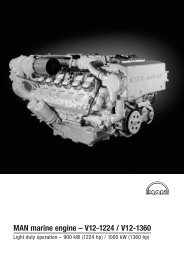
Commissioning and operationEngine views D 2840 LE 4031 2 3 4 5 6 7 81312111098 7 618 9 17 16 15 1414
Commissioning and operation1 Heat exchanger and coolant surge tank2 Relief valve on coolant surge tank3 Intercooler4 Coolant filler neck5 Oil filler neck6 Oil separator valve for crankcase breather7 Air intake8 Turbocharger9 Exhaust pipe10 Oil dipstick11 Starter motor12 Oil sump13 Engine cranking device14 Alternator15 Water pump (engine coolant circuit)16 Oil drain plug17 Speed sender18 Oil filter15
Commissioning and operationFirst commissioningWhen putting a new or overhauled engine into operation for the first time pay attention tothe “Installation instructions for MAN marine diesel engines” without fail.It is recommended that new or overhauled engines should not be operated at a loadhigher than about 75% maximum load during the first few hours of operation. Initial run-inshould be at varying speeds. After this initial run-in, the engine should be brought up tofull output gradually.Note:Use only approved fuels, lubricants etc. (see brochure “Fuels, lubricants etc.”).Otherwise the manufacturer’s warranty will become null and void.Filling with fuelCaution:Fill the tank only when the engine is switched off. Pay attention to cleanliness.Do not spill fuel.Use only approved fuels (see “Fuels, Lubricants etc.”).Filling-in of coolantFill the cooling system of the engine with a mixture of drinkable tap water and anti-freezeagent on ethylene glycole basis or anti-corrosion agent.See Publication “Fuels, Lubricants and Coolants for MAN Diesel Engines”.D Pour in coolant slowly via expansion tank, see page 57D For coolant filling quantity, see “Technical data”16
Commissioning and operationRaw water pumpDo not let raw water pump run dry.Make sure that all valves / cocks in theraw water circuit are open.If there is a risk of frost, drain the raw waterpump.Filling with engine oilCaution:Do not add so much engine oilthat the oil level rises above themax. marking on the dipstick.Overfilling will result in damage tothe engine.The engines are as a rule supplied withoutoil.Pour oil into engine via filler neck (arrow),see page 51.For the quantity required see “TechnicalData”.17
Commissioning and operationCommissioningBefore daily starting the engine, check fuel level, coolant level and engine oil level andreplenish, if necessary.Note:Use only approved fuels, lubricants etc. (see brochure “Fuels, lubricants etc.”).Otherwise the manufacturer’s warranty will become null and void.Checking oil levelCheck engine oil level only approx.20 minutes after the unit has beenswitched off.D Pull out dipstick (arrow)D wipe it with a clean, lintfree clothD and push it in again up to the stopD Pull out dipstick againThe oil level should be between the twonotches in the dipstick and must never fallbelow the lower notch. Top up oil as necessary.Oil?Caution:Do not add so much engine oilthat the oil level rises above themax. marking on the dipstick.Overfilling will result in damage tothe engine.MAXMINEnsure outmost cleanliness when handlingfuels, lubricants and coolants.18
Commissioning and operationStartingDanger:Before starting make sure that no-one is in the engine’s danger area.Caution:When starting do not use any additional starting aids (e.g. injection with startingpilot).Ensure that the gearbox is in neutral.Insert starter key and turn it to position “I”. The check lamp comes on to show that theengine is ready for operation.Turn starter key further to position “II” (pre-glow). The display lamp (usually in the driver’sstation) comes on.After the pre-glow period the display lamp begins to flash. This signalizes that the engineis ready for starting.Note:If the engine is not equipped with a pre-glowing function, immediately turn thestarter key through to position “III”.Turn key further up to the stop (position “III”). The display lamp goes out. The starter motoris actuated.Lube oil pressure must build up at the oil pressure gauge. If it does not, switch off the engineimmediately.Do not operate starter for longer than 10 seconds at a time.After ignition of the engine, release the starter button and adjust control lever for desiredspeed.If engine fails to start, release the key, wait about 30 seconds, then operate starter again.For repeated starting turn the key back to OFF.If the engine is kept idling for long periods it may cool down and thus start to emit whiteor blue smoke.We therefore recommend that you do not let the engine idle for more than 5 minutes.It is well known that with any internal combustion engine wear is higher during idling.Idling for longer periods is also an environmental nuisance.19
Commissioning and operationOperation monitoringThe D 2840 LE 403 / D 2842 LE 404 is equipped as series standard with a monitoringand diagnostic system MMDS.On the control console and alternatively on other control stands, the following display devicesare available for monitoring operation:1. Analog round instruments, see below2. Display device MMDS-L, see page 213. Display device MMDS-LC, see page 234. Engine room panel MMDS-EP, see page 31For operation and speed adjustment, MAN provides the following equipment:5. Drive lever control system Mini Marex made by Mannesmann-Rexroth, see page 326. Optional: Emergency unit Em, see page 421. Round instrumentsMAN can supply the following VDO round instruments for operation monitoring:Revolution counter with integrated digital hours of operation counterOil pressure engine0–6 barOil pressure gearbox0–25 barOil temperature engine50–150°CCoolant temperature engine40–120°CExhaust temperature engine100–900°CVoltmeter18–32 V20
Commissioning and operation2. Display device MMDS-LThe engine monitoring alarms the officerguiding the ship when important engineoperating values are outside the permittedtolerance range.D Acoustically by means of an integratedbuzzer or horn connected at the shipyardD Visually in that the relevant warninglamp flashesThe engine operating parameters shownon the display device are monitored.If gearbox parameters are to be monitored,this depends whether the correspondingsensors have been fitted in thegearbox.Engine in operationGenerator/speed sensorEngine oil pressureEngine coolant temp.Charge air temperatureCool. press. water pumpElectronics failureMAN MARINE DIESELCool. press. expans. tankExhaust gas temperatureEngine oil temperaturePressure air filterGearbox oil pressureGearbox oil temperatureBoost pressureCoolant levelOverspeedAlarmEngine slow downSensor failureTYP MMDS–LTESTRESETSystemFault51.27720–7008The device distinguishes between the following types of alarm, error messages:D Preliminary alarm: the corresponding light-emitting diode flashesD Main alarm: the corresponding light-emitting diode flasheslight-emitting diode “Alarm” flashesIn the case of an engine slow down alarm,“Engine slow down” also flashesIn the case of a stop alarm, “Engine stop” also flashesD Sensor fault: the corresponding light-emitting diode flasheslight-emitting diode “Sensor fault” flashesThe alarm “Sensor fault” means that the corresponding sensor is classified by the monitoringsystem as defective, as it is returning an unrealistic value.The engine speed is not reduced.In the event of a fault in the electronic system, the warning lamp lights up continuously.There is then a defect in the electronic fuel injection (EDC).So as not to endanger the engine, the engine power is automatically reduced in the caseof selected main alarms.Note for engines with electronically controlled diesel injection (EDC):After the ignition has been switched on, the lamp “Electronic fault” lights up briefly(lamp test). If there is a fault in the electronically controlled diesel injection (EDC),the lamp “Electronic fault” lights up permanently.21
Commissioning and operationOperation of the display device MMDS-LThe display device has the following operating keys:Switches off the alarm horn and the integrated buzzerSwitches off the flashing signal of the relevant warning lamp, i.e. the flashing lightswitches to continuous light. Before the flashing signal is cleared, the alarm hornmust be switched off.Clears the alarm message (red warning lamp goes out)Requirement for clearing an alarm message is:– Pressing the keys “Horn off” and “Test” in that order– Removing the cause of the alarm– In the event of a reduction alarm the engine speed must be brought downbelow 800 rpm in order to be able to reach higher speeds again– In the case of a stop alarm, the alarm can only be deleted if the engine is at astandstillFunction test of the warning lampsIf there is no alarm, the warning lamps can be tested.When the “Test” key is pressed, all the warning lamps must light upDimmingAll alarm LEDs are dimmed automatically depending on the ambient brightness. A photoelectricelement integrated in the front plate ensures this.Horn testIf the ’Clear horn’ key is pressed for approx. 5 seconds, the fitted buzzer as well as possiblyhorns fitted at the shipyard go off.System FailureTwo failure states are distinguished and indicated by the failure LED flashing or lightingup continuously:D A flashing System Failure LED signals a communication fault, i.e. the data bus is interruptedor there is interference. In this case, the seating of plug-in connections for theMMDS-L and the serial distributor MMDS-SD are to be checked.D Continuous lighting up of the System Failure LED indicates an internal fault. If thisstate remains after switching off and on again, the device is defective.22
Commissioning and operation3. Display device MMDS-LCThe device serves to visualise analog enginedata, as well as visual and acousticnotification of engine alarms. All enginedata is entered at the factory in the languagesGerman, English, French, Italianand Spanish.“Scrolling” with the PAGE key enables theuser to call up all the important enginedata. Another key is used to show currentalarms or warnings.MAN MARINE DIESELM Motordrehzahl1835 upm1 Oeldruck Motor4.3 bar Engine runKuehlwassertemp.Motor 83 CA Ladelufttemperatur 64 C3AlarmOeltemp. Motor 120 CSystem fail.51.27720–7015TYP MMDS–LCALARMS PAGE RESET TESTMenPrg23
Commissioning and operationRepresentation of monitor pagesThe analog engine data provided by the MMDS is distributed on 4 monitor pages. Oneach page, the current engine speed is displayed in the top line. The 1st page continueswith the most important engine data such as oil pressure, coolant pressure, charge-airpressure and oil pressure in the gearbox. Other engine and gearbox data, as well as exhausttemperatures and supplementary information is shown on the subsequent pages:Page 1Actual value (example)P1 Engine speed 2100 rpmOil pressure, engine 4,3 barCoolant temperature, engine 82 °CCharge-air temperature 41 °COil pressure, gearbox 19 barPage 2Actual value (example)P2 Engine speed 2100 rpmCoolant pressure compensator 830 mbarreservoirCoolant pressure water pump 3,9 barOil temperature, engine 103 °CBattery voltage 27,1 VPage 3Actual value (example)P3 Engine speed 2100 rpmIntake air vacuum 30 mbarCharging pressure 1,86 barExhaust temperature T.A. 629 °CExhaust temperature T.B. 613 °CPage 4Actual value (example)P4 Engine speed 2100 rpmFuel consumption 162 l/hEngine load 79 %The pages are scrolled using the “PAGE” key. Each time the key is pressed, the screenmoves up to the next page. After page 4, page 1 appears again.For the display of current alarms and warnings, an alarm screen has been included. Thisis called up using the “ALARMS” key. If there is no alarm, the message “no message”appears on the screen.A1> no message24
Commissioning and operationWhen the acoustic acknowledgement (Horn Quit key) has been pressed, the integratedbuzzer switches off. With the visual acknowledgement (Visual Quit key), the flashing textand the LED “Alarm” switches to continuous display. When the fault has been remedied,the alarm text disappears from the monitor. The LED “Alarm” goes out unless anotheralarm has been issued.In the case of alarms that have led to automatic stopping or reduction of the enginespeed by the central unit MMDS, the “RESET” key must also be pressed. Thisfunction is only enabled in the case of a stop alarm at engine standstill and in thecase of a slow down alarm below an engine speed of 800 rpm.Horn testIf the ’Clear horn’ key is pressed for approx. 5 seconds, the built-in buzzer sounds.System FailureThe front plate of the device has a red LED with the description ’System Failure’. This isactivated in the following two cases:A Failure of the serial data from the Safety, Alarm and Diagnosis system MMDS in theengine terminal box. In this case, LED “Alarm” also flashes and the message “SystemFailure” appears on the alarm screen.B Fault in the LCD monitor itself. In this case, no other message appears.Key functionsThe front of the device has 5 keys that enable various functions such as scrolling, contrastadjustment, alarm acknowledgement and menu control. The keys have the followingfunctions: Standard, Test, Menu and Special functions.Horn Quit:PrgStandard function: acoustic acknowledgement or deactivation of theinternal horn. All other monitoring devices in the system are acknowledgedvia the serial bus.Test function: Holding the key for at least 5 seconds activates thebuilt-in buzzer.PRG menu function: adopt currently selected setting (Prg=program)26
Commissioning and operationVisual Quit / Test: Standard function: visual acknowledgement, i.e. all flashing alarmtexts in the currently visible alarm screen switch to constant representationif the horn was acknowledged beforehand; the red alarm LEDTESTintegrated in the front plate is also switched from flashing to continuouslighting. All other monitoring devices in the system are acknowledgedvia the serial bus.Test function if there is currently no alarm and / or all issued alarmshave been visually acknowledged beforehand: Lamp test, i.e. thethree LEDs in the front plate are activated as long as the key ispressed.Special function: see explanation of keyPAGE+-menu function: Shift selection cursor to the right or increase inputvalue.RESET:RESETStandard function: The reset key can be used to reset a slow down orstop alarm:A reduction alarm can only be reset after reduction of the speedbelow 800 rpm.If the corresponding criteria have been met, horn and optics / test buttonpressed / activated and the cause of the alarm eliminated, the reductionor stop alarm in the central processing unit is reset.Special function: see explanation of keyPAGE–-menu function: Shift selection cursor to the left or decrease inputvalue.PAGE:PAGEStandard function: Switch to next highest display screen for analog enginedata. The page number is indicated in the top left-hand side ofthe display with P1 to P4. Page 4 is followed again by page 1. If thiskey is pressed while the alarm screen is on display, the monitorswitches back to the analog engine data from which the alarm screenwas originally called.-Special function: Key enables setting of the LCD contrast with simultaneouspressing of the keysTESTorRESET.27
Commissioning and operationALARMS:ALARMSMenStandard function: Calling up the alarm screen; the five alarms orwarnings last issued and still present are displayed. At the top left ofthe monitor is the code A1. If there are more than 5 messages issued,the messages can be displayed in groups of five by pressing the keyagain. The page number is indicated in the top left with A1 to Ax. If thedisplay jumps to the 1st alarm screen or the display remains unchangedwhen the key is pressed, no more messages are active.Special function: Holding the key for at least 5 seconds activates thebuilt-in configuration menu. There, the language, units, date and timecan be set.Menu function: Within the menu, this key has a cancel function (Esc).The program moves back by one menu level and / or from the mainmenu to the normal display function.Menu functionsBy holding the “ALARMS” key (for at least 5 seconds), you enter the configuration menu.The keys are now given the significance described at “Menu function”. The new allocationis shown in the bottom line in continuous black:Escape functionCancelMove functionMove selection cursorEnter functionAccept settingesc(Men) move(+/–) enter(Prg)Menu guidance is in English and cannot be changed. You first enter the main menu,where the language and units for measurement point designations and measured valuescan be selected. There are also additional sub functions for time setting (set-time), aswell as service functions, incl. PC communication (service). Each current selection canbe cancelled using the Escape function (menu key ALARMS). All other previously made settingsare not influenced by this.MenSelection of language and unitsWhen the menu is opened, the current settings are shown highlighted in black. A flashingselection cursor marks the language currently set (e.g. English):English German French Italian Spanish> (US/GB) < (D) (F) (I) (E)28
Commissioning and operationThe selection cursor can be moved using the Move function (+– keysTESTRESET).The Enter function (PRG keyPrg) is used to accept each marked language and highlightit in black. The selection cursor then returns to the currently set unit for temperatures(e.g. °F):Display in degrees CelsiusDisplay in degrees Fahrenheit(°C) > (°F) (BAR) < (PSI)After selection and acceptance, all the settings for language and unit have been concludedand highlighted accordingly in black. The selection cursor jumps to the secondlast line to the item “exit”:>exit< back set-time serviceIf this is confirmed using the Enter function (PRG keyPrg) or you cancel at this pointusing the Escape function (Menu key ALARMS), you return with the currently marked modeMento the normal display function. In the event of an input error, you can use the function“back” to repeat the input. The selection cursor jumps back to the initial position (languageselection).Setting the timeFirst, the selection cursor must be placed in the second last line. To do so, the currentlanguage and unit settings are confirmed each time with the keyPrg. The selectioncursor can now be positioned using the +– keysTESTRESETto “set-time”.exit back > set-time < service29
Commissioning and operationThe function is called up using the PRG keyPrg .A new page is opened and the current time (time / date) is displayed.The selection cursor jumps to “Hour”.set-time hour minute secondtime (H:M:S) >13< : 29 : 56day month yeardate (D:M:Y) 27 : 06 : 00If nothing is to be changed, you can cancel using the Menu key ALARMS. Otherwise, thesetting is made using the +– keysTESTRESETand the PRG keyMenPrgin the orderHour, Minute, Second, Day, Month and Year. A correctly specified time or date is confirmedusing the PRG keyPrgand the selection cursor jumps to the next value. Theyear is given last, and the selection cursor jumps to the second last line to the item “exit”;the time setting is now concluded.>exit< Back get-mmds-timeYou return to the main menu by pressing the PRG keyPrgALARMSor the Menu key . Inthe event of an input error, you can use the function “back” to repeat the input.An additional function makes it possible to download the system time of the MMDS centralunit intothe display module. To do so, the selection cursor is placed on “get-mmds-time” andconfirmed withPRGPrg. If the central unit is active (engine ignition on), the date and time are overwrittenand thefollowing message appears briefly in the display.Men>>> LOAD MMDS-SYSTEM-TIME NO MMDS-TIME RECEIVED
Commissioning and operationShip-specific alarmsThere is the possibility to connect 11 ship-specific alarms or warnings and to generatethese using software. The text of the alarms or warnings is entered by the shipyard.In the event of an alarm, the corresponding measurement point text appears on thealarm page; the program switches automatically into the alarm menu. In the case ofwarnings, the program does not switch automatically into the alarm menu.4. Engine room panel MMDS-EPMAN MARINE DIESELM1A3Motordrehzahl 1835 upmMotoroeldruck 4.3 barKuehlwassertemp. 83 CLadelufttemperatur 64 CMotoroeltemperatur 120 CEngine runAlarm51.27720–7018System Fail.TYP MMDS–EPALARMSPAGERESETTESTMenPrgThe functions of the keys and of the LCD displays are the same as those on theMMDS-LC (see operating instructions for MMDS-LC).Differences to MMDS-LC:D no ship-specific alarms can be programmedD additional: –Ignition–Pre-glow plugNote on pre-glow plug:The pre-glow plug is not active in the in-line 6-cylinder engine (D 2876 LE401/404), as this engine is not equipped with a pre-glow system.On V-engines, pre-glow can be fitted as an option. In ignition position “I”, thelamp lights up. Wait until the lamp begins to flash, then start.31
Commissioning and operation5. Drive lever control system Mini MarexAt the request of the shipyard or customer, it is possible to purchase from MAN an electronicdrive lever control system made by Mannesmann Rexroth, type Mini Marex.This control system has plug connections specially configured for MAN.Operation of the control system:Command masterInfinitely variablespeed adjustmentGearbox forwards(lock)2Neutral(lock)12Gearbox reverse(lock)Infinitely variablespeed adjustmentForwards areaReverse area3Operating field3Max. speedMax. speedAcousticsignallingdevice“Neutral” (lock) position ÀIn this position, the gearbox clutch is disengaged and the power unit is idling. Each timethe “Neutral position” is reached, the control system indicates this acoustically by meansof a short “beep tone”.32
Commissioning and operation“Gearbox forwards / reverse” (lock) position ÁIn this lever position, two different functions are possible.1. Standard function:The gearbox clutch is engaged to “Forwards” or “Reverse”; the power unit is idling.2. “Increase engine speed” function:The “Increase engine speed” function is set (function switch II–8). The engine speedof the power unit is raised prior to engaging the clutch and after disengaging the clutchit is lowered again to idling speed. Between the clutch engaging operations, individualdelays (waiting periods BEFORE and AFTER clutch engaging) can be set.“Maximum engine speed” position ÂPosition  shows the “maximum engine speed” for the “Forwards and BackwardsRange”. Between positions Á and Â, the engine speed can be set variably.The gearbox clutch is engaged to “Forwards” or “Reverse”.Operating panel – command master for twin-engine systemsL1L2L3L4L5L6COMMANDSYNCHROTROLLINGCOMMANDSYN./TROL.T1L7L8T2Key “Command takeover” T1COMMANDThe “Command takeover” key occurs only once on the command master. Thekey is permanently illuminated weakly via LED L1 and indicates that the controlsystem is being supplied with voltage. The key serves to take over commandsonto the relevant control stand.The key has two other additional functions.33
Commissioning and operationAdditional function “Warming Up”The expression “Warming Up” means “engine running without shifting gear”, which enables,for example, warm-up of a cold power unit across the entire speed range. Thegearbox clutch is not engaged in lever position Á.Starting the “Warming Up” function:. The “Warming Up” function can only be started at an active command master and onlyfrom the position “À neutral”.1. Set the control lever of the command master in position “À neutral”.2. Press the key “Command takeover” and keep it pressed.3. Set the control lever of the command master in position “Á gearbox forwards / reverse”.The “Warming Up” function is indicated acoustically by a short “double beep” toneand visually by a brief, rhythmic extinguishing of the command master lighting.4. Release the “Command takeover” key.The engine idles and the gearbox clutch remains disengaged. The control lever can nowbe moved towards position “ maximum engine speed”. The entire engine speed rangebetween the positions Á and  is available.. In the case of twin-engine systems, any power unit can be run separately.Quitting the “Warming Up” function:To exit from the “Warming Up” function, the control lever of the command master must beset to position “À neutral”. The normal “beep” tone sounds for the “Neutral position”. Thecommand master lighting returns to continuous light. The function is disabled.Note:If the control lever is shifted from “Forwards” to “Reverse” or vice versa duringthe “Warming Up” function, the “Warming Up” function stops automatically whenposition “À neutral” is reached. When position “Á gearbox forwards / reverse” isreached again, the gearbox clutch would be engaged again.34
Commissioning and operationAdditional function: switch error message to muteThe acoustic signal transmitter, which is activated for some alarms, can be disabled atthe relevant control stand by pressing the “Command takeover” key.. However, this does not delete the alarm!Display Alarm L7 and L8This display element is present on the command master twice (once for the port system /once for the starboard system). In the event of a fault, the “Alarm lamp” lights up continuouslyin red.. When the control system is switched on, the “Alarm lamp” is also lit up continuously inred, but this is extinguished following command takeover.Key Syn./Trol. T2SYN/TROLThis key can be used to ENABLE and DISABLE special functions enabled beforehandin the setting unit (key is permanently illuminated weakly via LED 6).The following special functions are available for this setting unit:1. Engine speed synchronisation (only twin-engine systems)2. TrollingThe “Syn./Trol.” key can be used to operate both functions in parallel, but not simultaneously.Engine speed synchronisation (only possible with twin-engine systems)If the special function “Engine speed synchronisation” has been enabled in the settingunits, twin-engine systems provide the possibility to synchronise the engine speeds ofboth drive engines. For both drive engines to run synchronously, an engine speed feedbacksignal from a speed sensor is required for each engine.35
Commissioning and operationSYN/TROLPressing the “Syn./Trol.” key (press once) enables the “Engine speed synchronisation”function. Pressing the key again (press once) disables the function onceagain.It is only possible to enable or disable the engine speed synchronisation on theactive control stand when both command master levers are in the engine speedrange “Forwards” or during the “Warming Up” function. Before exiting from theseareas, disable the “engine speed synchronisation”.While the function is active, LED 4 “SYNCHRO” shows continuous light.. As soon as one of the command masters leaves the engine speed range “Forwards”without terminating the synchronisation beforehand, it is switched off automatically.In this case, the LED “SYNCHRO” flashes rapidly (approx. 0.2 seconds on / 0.2 secondsoff) and the acoustic signal transmitter issues a continuous tone at the activecontrol stand (this is not a fault alarm but a warning).The second command master must then be set into the “Neutral” position to terminatethe warnings. The engine speed of the relevant command master is kept at idlingspeed during this period.While the control system is in the function “Synchronisation”, the engine speeds of bothpower units can only be changed using the control lever of the “Master system”. If thereis a command change to another control stand, the active function “Engine speed synchronisation”is also taken over onto the new control stand.TrollingIf the special function “Trolling” has been enabled in the setting units, there is the possibilityto use the “Syn./Trol.” key to enable the trolling mode to continuously adjust theclutch slip.SYN/TROLPressing the “Syn./Trol.” key (press once) enables the “Trolling” function. Pressingagain (press once) disables the function once again.It is only possible to enable or disable the trolling function on the active controlstand when the command master lever (both command master levers in the casetwin-engine systems) is (are) in the “Neutral” position. While the function is active,LED L8 “Trolling” shows continuous light.If there is a command change to another control stand, the active function “Trolling”is also taken over onto the new control stand.. In the trolling mode, the command master function changes in comparison tothe power shift mode.The command master function in the trolling mode is described below.36
Commissioning and operationInfinitely variableslip adjustment andspeed increaseGear: forwardsClutch: 100% slip(lock)2Neutral(lock)1Gear: reverseClutch: 100% slip(lock)2Infinitely variableslip adjustment andspeed increaseForwards areaReverse area3Operating field3Clutch: 0% slip (grip)and max. speedwhen trollingClutch: 0% slip (grip)and max. speedwhen trollingAcousticsignallingdeviceTo enable the trolling function, the command master must be in position À “Neutral”(lock). The engine idles and the gearbox is in neutral.If the trolling mode is enabled, the clutch is set to its highest slip level (100% slip). Theengine continues to idle and the gearbox is in neutral.If the command master lever is set in position Á (lock), the gearbox is shifted into the“Forwards or Reverse” position. The engine idles, but due to the greatest possible clutchslip (100% slip) is not yet able to turn the propeller shaft, or can do so only very slowly.If the command master lever is moved further towards position Â, the clutch slip dropscontinuously and at the same time the engine speed rises.When position  is reached, the clutch is in the smallest possible slip position (0% slip /frictional connection) and the engine speed has reached the set value for “Maximum enginespeed for trolling”.37
Commissioning and operationAcoustic signal transmitterThe acoustic signal transmitter is located below the command master and ispresent once on each system (once for the port system and once for the starboardsystem).The signal transmitter supports the visual displays of the command master lightingand the alarm lamp with acoustic signals. In addition, each time the “Neutralposition” of the control lever is reached, it issues a short “beep tone”. The start ofthe “Warming Up” function is indicated by a short “double beep” tone.Display Command L2 and L3COMMANDContinuous light of the “Command” display indicates which command master is currentlyin command. The “Command” displays of the other control stands are disabled. If thecommand is requested on this master, the “Command” display flashes.If the command master is in the “Warming Up” function, this is indicated by a brief,rhythmic extinguishing of the “Command” display.The “Command” display is present on the system once (once for the port system / oncefor the starboard system).Enabling the control system with command masters1. Switch on control systemExecution:– apply supply voltage.Consequence: – Display “Alarm” (red) on all control stands lights up continuously.– “Command” and “Syn./Trol.” keys. On all control stands weaklylit up (only visible in darkness).– Acoustic signal transmitter sounds with slow intermittent tone on allcontrol stands.38
Commissioning and operation2. Command request:The command can be requested at any control stand. The control levers of the commandmaster on the requesting control stand must be set at the “Neutral position”.. “Command master calibration and enable of control stands” must have been carriedout. Otherwise, the command can only be taken over at control stand 1.Execution:– Set the control lever of the command master to the “Neutral position”.– Press “Command” key once for command request.Consequence: – Display “Alarm” (red) on all control stands remains lit up continuously.– Acoustic signal transmitter sounds with fast intermittent tone on allcontrol stands.– The display “Command” flashes rapidly.. If the control system continues to issue long lighting and tone intervals, it is usually thecase that the control lever of a command master is not in the “Neutral position”.3. Command takeover:Execution:– Press “Command” key once again for confirmationof command request.Consequence: – Display “Alarm” (red) goes out on all control stands.– Acoustic signal transmitter remains silent on all control stands.– “Command” display shows continuous light on the commandmaster in command.On all other command masters, the “Command” display is off.The command is now at this control stand. The control system is ready for operation(standby).39
Commissioning and operationCommand change between control standsFor a command change to a different control stand, there are two variants which have tobe set using DIP switch I–2 in the setting unit. Command change with lever comparisonor free command change.On twin-engine systems, both setting units must have the same setting.. “Command master calibration and enable of control stands” must have beencarried out.Otherwise, the command can not be changed between the individual control stands.Command change with lever comparisonThe control system compares the lever positions of the command masters involved in thecontrol stand change. A command change from one control stand to another can onlytake place if the lever of the requesting command master is either in the “Neutral position”or in the same travel direction position as the lever of the command master thatis in command.The command change for this variant takes place in two steps.1st step: Command request on the selected control stand.Execution:– Set the control lever of the command master in the takeover position(“Neutral” position or same travel direction as thecommand master that is in command).– Press “Command” key once to request the commandon this control stand.Consequence: – The acoustic signal transmitter “beeps” in short intervals.– The display “Command” flashes rapidly.The command is now requested on this control stand. The control system has enabledthe command takeover and indicates this by means of short tone and lamp intervals.. If the control system issues long lamp and tone intervals, the subsequent commandtakeover is refused. In this case, the control levers of the command master are usuallynot in the correct position or there is a fault in the system.40
Commissioning and operation2nd step: Command takeover on the selected control stand.Execution:– Press “Command” key once to take over the commandon this control stand.Consequence: – The acoustic signal transmitter is silent.– The “Command” display shows continuous light.The command takeover is complete and the command is now at this control stand.Free command change (without lever comparison)With this variant, a control stand change takes place without taking account of the leverposition of the command master involved in the command change. The commandchange takes place in one step.Command takeover on the selected control standExecution:– Press “Command” key (white) to take over the commandon this control stand.Consequence: – The “Command” display on the selected control standimmediately shows continuous light.The command is immediately at this control stand and the control system instantly runsthe lever position of the command master set here.In this variant, carelessness can lead to manoeuvres that are not intended.Example: Lever of the active command master is in position “Full forwards”.Lever of the requesting command master is in the position “Full reverse”. If therewere a command change, a full reverse manoeuvre would be performed immediately.41
Commissioning and operation6. Emergency operation unit:The emergency operation control system– Em – is conceived as a simple enginespeed and gearbox control system whichenables safe continuation of a trip in theevent of a failure in the electrical controllever system.The operating unit for the emergencyoperation control system is integrated preferablynear the control lever in the bridgecontrol console. For safe ship operation,the keys on the front must be easily accessible.When the ignition is on, emergencyoperation can be activated using thecorresponding function keys. A green LEDindicates standby mode.Operation is by means of six keys on thefront, which light up when a requestedmode is reached and thus return thecorresponding operating mode or actualmode.MAN MARINE DIESELEm.OpOnEm.op.off :engine stop + ignition offENGINEGEARBOX– +NPowerOnSystem–FailureEMERGENCY OPERATION UNITTyp Em–C51.27720–7012KeyKeyKeyEm. Op.OnNActivate emergency operationShift gearbox to neutral positionShift gearbox to forwards positionKeyKeyKey+–Shift gearbox to reverse positionIncrease engine speedDecrease engine speedLED Power On indicates the presence of supply voltage when the ignition is onLED System Failure indicates failure status by flashing or with continuous light42
Commissioning and operationOperating the emergency operation unitRequirements for operation / activation / deactivation:D Operation of the emergency operation control system is only permitted in neutral positionof the command master of the control lever systemD The emergency operation control system should only be activated when the engine isrunning. Otherwise, the LED “System Failure” flashing indicates that the engine speedsignal is missingD The engine should be switched off using the ignitionWhen the emergency stop switch is activated while the ignition is on, the LED “SystemFailure” lights up on the Em-C operating unit, as the active systems EDC engine controland emergency operation unit are switched off by the emergency stop.The LED “System Failure” goes out when the emergency stop switch is unlocked.Operation / function of emergency operation unit in operation:Enabling emergency operation unitThe system is ready for operation (standby) after the ignition is switched on. This is indicatedby the green LED “Power On”. The red LED (Failure) must not light up.Pressing the “EM.Op On” key twice can now activate the emergency operation system:Em.OpOnThe first press of the key requests emergency operation. The key flashes for approx.6 seconds in cycles and an acoustic signal is sounded. During this period,the request must be confirmed by a second press of the key. The key lights uppermanently as soon as emergency operation has been activated.If the confirmation by the second press of the key is not given, the system returnsto the initial position (power on – standby).Note:Once the emergency operation system has been activated, switching back tonormal control lever operation only takes place when the engine is switched off(at least 3 seconds ignition OFF).43
Commissioning and operationGearbox controlWith emergency operation active, the gearbox is controlled using 3 key functions in thepositions Neutral, Forwards or Reverse:KeyKeyNShift gearbox to neutral positionShift gearbox to forwards positionKeyShift gearbox to reverse positionGearbox shifting only takes place when the engine speed is in the idle range.It is advisable always to switch the gearbox into neutral first prior to reversing.However, if reverse is requested directly after forwards (or vice versa) and the engine isat a higher speed, the engine is automatically returned to idling speed prior to each activegear shift.As long as the desired state has not yet been reached, the key that has been pressedflashes.It goes out as soon as another control command is issued or it signals with continuouslight that the gear shift has taken place (display of the actual state).Engine speed controlIf the gearbox is in forwards or reverse position, two key functions can be used to increaseor decrease the current engine speed:KeyKey+–Increase engine speedDecrease engine speedAs long as the + or – keys are pressed (“Tastensysmbol einfügen”), there is a continuouschange in the engine speed.The rate of increase and / or rate of change is 50 revolutions per second.With a single brief press of the key, the engine speed changes by 10 engine revolutions.The engine speed is restricted downwards to the idling speed and upwards to the maximumpermitted engine speed.44
Commissioning and operationDisabling emergency operationEmergency operation is always terminated automatically when the engine is switched off;the ignition must be switched off for at least 3 seconds.After switching on again, normal control lever operation is enabled first, i.e. the emergencyoperation system must be reactivated if required.Fault messagesTwo LEDs on the Em-C operating unit (green LED “Power On” and red LED “Failure”)enable the distinction of various failure states:Green LED off and red LED offIgnition switched off or no supply voltage(emergency operation not possible)Green LED on, red LED flashing without any other operating key also flashingFailure of the internal engine speed signal(function still possible with delayed shift times)Green LED on, red LED flashing together with the forwards keyFault following gear shift in forwards direction(this travel direction can no longer be activated)Green LED on, red LED flashing together with the reverse keyFault following gear shift in reverse direction(this travel direction can no longer be activated)Green LED and red LED continuously onSystem failure or no communication between Em-C and Em-R.(emergency operation not possible)Em-R is the receiver component in the terminal box.Fault states that are indicated by flashing on the Em-C operating unit must be acknowledgedusing the (N) key after the fault has been rectified. Until this acknowledgement,the fault message continues to flash.45
Commissioning and operationMain fuses for + / – on the engineTwo main fuses with 20 A are fitted at the engine; these blow in the event of overcurrentor short circuit.If a fuse as blown, the engine can no longer be started.The fuses can be reset by the operator using the keys fitted.There are two different possibilities for fitting the fuses:Fitting with fuse boxFitting without fuse box46
Commissioning and operationMain fuses on terminal boxThree more main fuses are fitted in theterminal box.These fuses blow in the event of overcurrentor short circuit.They separately protectD the electronic fuel injection EDC,F5=16 AD the diagnosis system, F6=10 AD and the external electrical connections,F7=10 AThe fuses can be reset by the operatorusing the keys fitted.Top side of terminal box with the keysfor fuses F5 / F6 / F7Charge control lamp on the terminal boxA charge control lamp is fitted on the terminalbox.This should only light up at “Ignition on”.As soon as the engine is running, thislamp should go out.If it lights up when the engine is running,there is a defect in the dynamo.The battery is no longer being charged.The monitoring system reports the fault“Failure of charge voltage”.A restart can thus be a problem.Top side of terminal boxwith charge control lamp47
Commissioning and operationTerminal box in the engine room / interface with light-emitting diodes + keysMAN Marine DieselTESTRESETSerial data activityTYP BE3The terminal box with light-emitting diodes functions at the same time as an engine roommonitoring panel.If an alarm is issued, the corresponding light-emitting diode lights up. The following relaysare activated on the diagnosis unit:D Engine slow down (main alarm) = reduction of engine speedD Horn = acoustic alarmD Group alarm = collective fault indicationThe keys are intended for:D Horn offSwitches off the alarm horn and the integrated buzzerD Flashing light off, transition to continuous light / test of light-emitting diodesSwitches off the flashing signal of the relevant warning lamp, i.e. the flashinglight switches to continuous light. Before the flashing signal is cleared, thealarm horn must be switched off.D ResetClearing the alarm message (red warning lamp goes out)Requirement for clearing an alarm message is:– Pressing the keys “Horn off” and “Test” in that order– Removing the cause of the alarm48
Commissioning and operation– In the case of an engine slow down alarm, short-term lowering of enginespeed below 800 rpm so that higher engine speed can be reached– In the case of a stop alarm, the alarm can only be deleted if the engine is ata standstillThe following light-emitting diodes function continuously:D Power on:Diagnosis unit is receiving voltageD Ignition:Ignition is onD Serial data activity: Data interchange at the bridge.If this fails, no more data is displayed on the bridge, neitheron the display (MMDS-L /-LC) nor on the round instruments.The two light-emitting diodes below the “Horn off” key mustalways be functioning.The light-emitting diode below the “Test” key only reacts whenalarms are acknowledged.If the following light-emitting diodes light up, there is a faultD Diagnostic unit failure: The diagnosis unit is defectiveD Sensor failure: A sensor is defective. The measurement point of the defectivesensor flashes with the same frequency as “Sensor failure”D Speed sensor failure: Defective engine speed inputD Remote slow down: Remote reduction of speed.Alarm at other engine. The defective engine reducesthe intact engine.This prevents a curving manoeuvre in the case of an alarm.Shutting downAfter the engine has been running at a high load level, do not shut it down immediatelybut allow it to idle about 5 minutes so that temperatures may equalize.Set deck switch to “Neutral” and switch off the engine at the ignition key.Remove key from starting lock.Danger:Ensure that the engine can not be started by unauthorized persons.49
Maintenance and careLubrication systemEnsure outmost cleanliness when handling fuels, lubricants and coolants.Note:Use only approved fuels, lubricants etc. (see brochure “Fuels, lubricants etc.”).Otherwise the manufacturer’s warranty will become null and void.Engine oil changeDanger:The oil is hot- risk of scalding. Donot touch the oil drain plug withbare fingers. Oil is an environmentalhazard. Handle it with care!With the engine at operating temperature,remove the oil drain plugs on the oil sumpand the oil filter bowl and allow the old oilto drain off completely.Use a vessel of sufficient size to ensurethat the oil does not overflow.As the oil drain plug is often not accessible,a manually operated vane pump maybe attached to the engine for draining theoil.Pump the old oil out of the sump while theengine is still warm. Remove oil drainplugs in oil filter bowl and let old oil drainout of oil filters. Use a vessel of sufficientsize to ensure that the oil does not overflow.Refit the oil drain plugs with new gaskets.Note:Change the oil filter elements everytime the engine oil is changed50
Maintenance and careRefilling with oilCaution:Do not add so much engine oilthat the oil level rises above themax. marking on the dipstick.Overfilling will result in damage tothe engine.Refill with fresh engine oil at the oil fillerneck (arrow).After filling start the engine and let it runfor a few minutes at low speed.Caution:If no oil pressure builds up afterapprox. 10 seconds switch off theengine immediately.Check oil pressure and check that there isno oil leakage.Then shut down the engine. After about20 minutes, check the oil level.D Pull out dipstick (arrow)D wipe it with a clean, lintfree clothD and push it in again up to the stopD Pull out dipstick againOil?The oil level should be between the twonotches in the dipstick and must never fallbelow the lower notch. Top up oil as necessary.MAXMINChanging oil filterA changeover-type oil filter, the filter elementsof which can be replaced even duringoperation, can be fitted on request.However, oil filter cartridges must bechanged at every oil change.51
Maintenance and careDuring continuous operation position theselector lever that both filter halves are inoperation.Observe positions of selector lever!Caution:Do not leave selector lever in anyintermediate position because thiswould be liable to interfere with oilsupply. If in doubt stop engine tochange oil filter.Continuous operation(both filter halvesin operation)Right-hand filtercut outLeft-hand filtercut outRenewal of filter cartridgesD Allow the filter content to run off alongdrain plugs Ã.Hold a suitable vessel under hole18Danger:The oil is hot and under pressurewhen the drain plug is opened.Risk of burns and scalds.47D After releasing the clamping bolts Çremove filter bowls ÆD Renew filter cartridges Ä. Thoroughlyclean all other parts in cleaning fluid(do not allow cleaning fluid to enter theoil circuit)D Use new gaskets Å for reassembly offilter bowls425Note:To prevent the seal Å from twistinghold the filter bowl Æ firmlywhen tightening the tensioningscrew Ç.Caution:Used oil filters are classed as dangerouswaste and must be disposedof accordingly.31 Oil filter, standard design(non-changeover)2 Oil filter, changeover-type3 Selector cock4 Oil drain plugs5 Filter cartridge6 O-ring7 Filter bowl8 Clamping bolt652
Maintenance and careFuel systemFuelIf Diesel fuel which contains moisture is used the injection system and the cylinder liners/ pistons will be damaged. This can be prevented to same extent by filling the tank assoon as the engine is switched off while the fuel tank is still warm (formation of condensationis prevented). Drain moisture from storage tanks regularly. Installation of a watertrap upstream of the fuel filter is also advisable. Do not use any additives to improveflow properties in winter.Injection pumpNeither the injection pump nor the control unit must be modified in any way. If the leadseal is damaged the engine warranty will become null and void.FaultsWe urgently recommend that you have faults in the injection pump rectified only in an authorizedspecialist workshop.Cleaning fuel pre-cleanerStrip the fuel pre-cleaner:D Remove filter housing ÀD Wash out filter housing À and gauzefilter Á in clean Diesel fuel and blowthem out with compressed airD Reassemble using new sealD Screw on filter housing and tighten it to10–12 Nm1 2D Actuate plunger of hand priming pumpuntil the overflow valve of the injectionpump opens audiblyD Screw in the tappet of the hand pumpagain and tighten itD Start engineD Check fuel pre-cleaner for leaks53
Maintenance and careParallel fuel filterChanging fuel filterOnly when engine is switched offD Loosen filter cartridge by means of tapewrench, unscrew it by hand and take itoffD Moisten the seals on the new filter cartridgewith fuelD Screw on the filter cartridges andtighten them vigorously by handD Bleed fuel systemD Check filter for leaksCaution:Used fuel filters are classed asdangerous waste and must be disposedof accordingly.Change-over fuel filterWhere the changeover-type filter isinstalled, the servicing procedure is for thefilter side requiring to be shut off with theengine running. During continuous operation,the selector lever should be placedin a position where both filter halves are inoperation.Caution:Do not leave selector lever in anyintermediate position because thiswould be liable to interfere withfuel supply. If in doubt stop the engineto change the fuel filter.Continuous operation(both filter halvesin operation)Right-hand filtercut outLeft-hand filtercut out54
Maintenance and careChanging fuel filterD Loosen filter cartridge by means of tapewrench, unscrew it by hand and take itoffD Moisten the seals on the new filter cartridgewith fuelD Screw on the filter cartridges andtighten them vigorously by handD Bleed fuel systemD Check filter for leaksCaution:Used fuel filters are classed asdangerous waste and must be disposedof accordingly.Bleeding the fuel systemNote:To bleed the fuel system switch onthe “ignition” so that the EHAB willbe open.An arrow on the filter head indicates thedirection of fuel flow.D Unscrew bleed screw of first filter in directionof flow by one or two turnsD Actuate tappet of hand primer until fuelemerges without bubblesD Screw in the tappet of the hand pumpagain and tighten itD Close bleed screw againD Repeat this procedure at the secondbleed screwD Check fuel system for leaks55
Maintenance and careCooling systemDanger:Draining hot coolant involves a risk of scalding.Draining the cooling systemCaution:Drain coolant into a suitable containerand dispose of it in accordancewith regulations.1Drain coolant as follows, but only whenthe engine has cooled down:D Briefly open cap À (large cap) on thefiller neck of the expansion tank forpressure compensation2 3D Remove drain screws in exhaust manifoldÁ, oil cooler housing Â, coolantpipe à and crankcase ÄD Then remove cap ÀD Drain coolant into a container of adequatesize4D Refit screw plugs5D Filling / bleeding the cooling system56
Maintenance and careFilling / bleeding the cooling system (only when engine has cooled down)Fill the cooling system of the engine with a mixture of drinkable tap water and anti-freezeagent on ethylene glycole basis or anti-corrosion agent.See Publication “Fuels, Lubricants and Coolants for MAN Diesel Engines”.Coolant must be added at the fillerneck only À (large cap). When toppingup do not add cold coolant if the engine isstill warm from operation. Ensure that theratio of water to anti-freeze is correct. Findthe cause of the loss of coolant and haveit eliminated.1D Remove cap À (large cap)D Fill in the coolant slowlyD During the filling procedure the liquidcooledturbochargers and the intercoolermust be bled. For this there arebleed screws on the diffusor Á and onthe intercooler Â. These must remainopen until coolant emerges withoutbubbles or until the coolant level reachesthe filler neck (depending on installationposition)2D Let engine run at a speed of 2,000 rpmfor approx. 15 minutesD Switch off engine, carefully turn cap Àwith safety valve to the first detent torelieve pressure and then carefully removecap and top up with coolant3Danger:Risk of scalding and burning yourself!57
Maintenance and careD Before the engine is next put into operation (with the engine cold) check the coolantlevel and top up if necessaryD Repeat this procedure until no more coolant can be addedNote:The turbochargers must not be bled while the cooling system is being topped up.Danger:If, in an exceptional case, the coolant level has to be checked in an engine thathas reached operating temperature, first carefully turn the cap À (large cap) withsafety valve to the first stop, let off pressure, then open carefully.Note:Don’t open the cooling system when the engine is at operating temperature.This causes a pressure loss in the cooling system.If the cooling system has been opened when the engine is at operating temperaturethis can lead to the alarm “pressure in the expansion tank” when the engineis then put into operation and to a reduction in the engine output.Coolant pressure in the expansion tank is only built up again when the enginehas cooled down. The cooling system must therefore only be filled up when theengine is cold.58
Maintenance and careV-beltsChecking conditionD Check V-belts for cracks, oil, overheatingand wearD Change demaged V-beltsChecking tensionUse V-belt tension tester to check V-belttension.D Lower indicator arm À into the scale1D Apply tester to belt at a point midwaybetween two pulleys so that edge ofcontact surface Á is flush with theV-beltD Slowly depress pad  until the springcan be heard to disengage. This willcause the indicator to move upwards2If pressure is maintained after the springhas disengaged a false reading will beobtained!3Reading of tensionD Read of the tensioning force of the beltat the point where the top surface ofthe indicator arm À intersects with thescaleD Before taking readings make ensurethat the indicator arm remains in itspositionDrivebeltwidthTensioning forces accordingto the kg graduation on thetesterNew installationInstallationAfter 10min. runningtimeWhenservicingafterlong runningtime2/3VX 90–100 70–80 60If the value measured deviates from thesetting value specified, the V-belt tensionmust be corrected.59
Maintenance and careTensioning and changing V-beltAlternator 120AD Remove mounting nut ÀD Turn setting screw Á in clockwise directionuntil the tension of the V-belts iscorrect.D Retighten mounting nut.To change the V-belts turn the settingscrew anti-clockwise1 255 A alternator on heat exchangerD Remove fixing bolts ÀD Remove lock-nut ÁD Adjust nut  until V-belts have correcttensionsD Retighten lock-nut and fixing boltsTo replace the V-belts loosen lock-nut andswing alternator inwards.123Tension pulley at bottom rightD Remove fixing bolts ÀD Remove lock-nut ÁD Adjust nut  until V-belts have correcttensionsD Retighten lock-nut and fixing boltsTo change the V-belts turn the adjustingnut back and swing the tension pulley inwards.2 3155 A alternator at bottom rightD Remove fixing bolts ÀD Remove lock-nut ÁD Adjust nut  until V-belts have correcttensionsD Retighten lock-nut and fixing boltsTo replace the V-belts loosen lock-nut andswing alternator inwards.13260
Maintenance and careAlternatorThe alternator is maintenance-free.Nevertheless, it must be protected against dust and, above all, against moisture.In order to avoid damage to the alternator, observe the following instructions:While the engine is runningD Do not de-energize the main battery switch!D Do not disconnect the battery or pole terminals or the cables!D If, durig operation, the battery charge lamp suddenly lights up, stop the engineimmediately and remedy the fault in the electrical system!D Do not run the engine unless the battery charge control is in satisfactory order!D Do not short-circuit the connections of the alternator with those of the regulator or saidconnections with ground, not even by briefly bringing the connections into contact!D Do not operate the alternator without battery connection!Temporary decommissioning of enginesTemporary anti-corrosion protection according to MAN works norm M 3069 is required forengines which are to be put out of service for fairly long periods.The works standard can be obtained from our After-Sales Service department in Nuremberg.61
Technical dataModel D 2840 LE 403Design V 90°Cycle 4-stroke Diesel with turbocharging /intercooling and wastegateCombustion systemTurbochargingDirect injectionTurbocharger with intercoolingand wastegateNumber of cylinders 10Bore128 mmStroke142 mmSwept volume 18 270 cm 3Compression ratio 13.5 : 1Ratingsee engine nameplateFiring order 1-6-5-10-2-7-3-8-4-9Valve clearance (cold engine)IntakeExhaustValve timingIntake opensIntake closesExhaust opensExhaust closesFuel systemInjectionGovernorStart of deliveryup to engine No. ... 9218 039 ....from engine No. ... 9218 040 ....InjectorsOpening pressure of injectorNew nozzle holderUsed nozzle holder0.50 mm0.60 mm12° before TDC48° after BDC61° before BDC11° after TDCIn-line pumpElectronic Diesel Control(EDC) - Model M(S) 524°±1° before TDC21°±1° before TDCfive-hole nozzles290+8 bar280+8 bar62
Technical dataEngine lubricationForce feedOil capacity in oil sump (litres) min. max.shallow 32 l 38 ldeep (front end sump) 26 l 30 ldeep (V48) 38 l 48 lOil change quantity (with filter)shallowdeep (front end sump)deep (V48)Oil pressure during operation (dependingon oil temperature, oil viscosityclass and engine rpm)41 l33 l51 lmust be monitored by oil pressure monitors/ gaugesOil filterEngine cooling systemCoolant temperatureCoolant filling quantityFull flow filter with two paper cartridgesLiquid cooling80-85°C, temporarily 90°C allowed80 lElectrical equipmentStarterAlternator24 V; 6.5 kW28 V; 55, 120 A63
Technical dataModel D 2842 LE 404/407/410/414/415/416/417Design V 90°Cycle 4-stroke Diesel with turbocharging /intercooling and wastegateCombustion systemTurbochargingDirect injectionTurbocharger with intercoolingand wastegateNumber of cylinders 12BoreStroke128 mm142 mmSwept volume 21 930 cm 3Compression ratio 13.5 : 1Ratingsee engine nameplateFiring order 1-12-5-8-3-10-6-7-2-11-4-9Valve clearance (cold engine)IntakeExhaustValve timingIntake opensIntake closesExhaust opensExhaust closesFuel systemInjectionGovernor0.50 mm0.60 mm24° before TDC36° after BDC63° before BDC27° after TDCIn-line pumpElectronic Diesel Control(EDC) - Model M(S) 5Start of deliveryD 2842 LE 404up to engine No. ... 9029 045 ....from engine No. ... 9029 046 ....D 2842 LE 410 / 415D 2842 LE 407 / 414 / 416 / 417Injectors23°±1° before TDC21°±1° before TDC19°±0,5° before OT20°±0,5° before OTfive-hole nozzlesOpening pressure of injectorNew nozzle holderUsed nozzle holder290+8 bar280+8 bar64
Technical dataEngine lubricationForce feedOil capacity in oil sump (litres) min. max.deep 24 l 32 ldeep (V70) 60 l 70 lsemi-shallow 22 l 30 lfor 38 / 45° tilt 37 l 45 lOil change quantity (with filter)deepdeep (V70)semi-shallowfor 38 / 45° tiltOil pressure during operation (dependingon oil temperature, oil viscosityclass and engine rpm)Oil filterEngine cooling systemCoolant temperatureCoolant filling quantity35 l73 l33 l48 lmust be monitored by oil pressure monitors/ gaugesFull flow filter with two paper cartridgesLiquid cooling80-85°C, temporarily 90°C allowed96 lElectrical equipmentStarterAlternator24 V; 6.5 kW28 V; 55, 120 A65
Troubleshooting tableFaultEngine does not start, or starts only with difficultyEngine starts but does not reach full speed or stallsEngine idles out of true when warm, misfiringEngine speed fluctuates during operationPower output unsatisfactoryCoolant temperature too high, coolant being lostLube oil pressure too lowLube oil pressure too highBlack smoke accompanied by loss of powerBlue smokeWhite smokeKnocking in the engineEngine “too loud”ReasonDFuel tank emptyDFuel cock closedD D D D D Air in fuel systemD D D D D Fuel pre-filter / pre-cleaner cloggedDCondensation in fuelD D D D Air filter cloggedDElectric circuit interruptedDBatteries flatDStarter / solenoid switch defectiveD D D D D Start of delivery not correct / incorrectly setDInjection nozzles cloggedDInternal damage to engine(piston seized, possibly caused by water in fuel)D D D Fuel quality not in accordance with specifications or fueledseverely contaminatedDLower idling speed set too lowD D D D Valve clearance incorrectDInjection nozzles of injection pipes leakingDToo little fuel in tankDRev. counter defectiveD D D Injection nozzles defective or carbonizedDEngine being asked to do more than it has toDFuel supply faulty, fuel too warmD D Oil level in sump too highDIncorrect rated speed settingDCoolant level too lowDAir in coolant circuit66
Troubleshooting tableFaultEngine does not start, or starts only with difficultyEngine starts but does not reach full speed or stallsEngine idles out of true when warm, misfiringEngine speed fluctuates during operationPower output unsatisfactoryCoolant temperature too high, coolant being lostLube oil pressure too lowLube oil pressure too highBlack smoke accompanied by loss of powerBlue smokeWhite smokeKnocking in the engineEngine “too loud”ReasonDTension of water-pump V-belts incorrect (slip)DCap with working valves on expansion tank / radiator defectiveor leakingDTemperature gauge defectiveDCoolant pipes leaking, blocked or twistedDOil level in sump too lowDEngine temperature too highDOil filter cloggedD DOil pressure gauge defectiveD DSelected oil viscosity not suitable for ambient temperature(oil too thin)DOil in sump too thin (mixed with condensation or fuel)DEngine coldD D Engine, coolant or intake air still to coldD Lube oil getting into combustion chamber(piston worn, piston rings worn or broken)D Overpressure in crankcase (crankcase breather clogged)D long operation under a low loadD Coolant getting into combustion chamber(cylinder head / gasket leaking)D Engine operating temperature incorrectD Intake or exhaust pipe leaking67
IndexAAlternator . . . . . . . . . . . . . . . . . . . . . . . . . . . . . . . . 61BBleeding the fuel system . . . . . . . . . . . . . . . . . . . 55CChanging oil filter . . . . . . . . . . . . . . . . . . . . . . . . . . 51Checking oil level . . . . . . . . . . . . . . . . . . . . . . . . . . 18Cleaning fuel pre-cleaner . . . . . . . . . . . . . . . . . . . 53Commissioning . . . . . . . . . . . . . . . . . . . . . . . . . . . 18Commissioning and operation . . . . . . . . . . . . 14–49Cooling system . . . . . . . . . . . . . . . . . . . . . . . . 56–58DDeclaration . . . . . . . . . . . . . . . . . . . . . . . . . . . . . . . . 8Draining the cooling system . . . . . . . . . . . . . . . . . 56EEngine oil change . . . . . . . . . . . . . . . . . . . . . . . . . 50Engine views . . . . . . . . . . . . . . . . . . . . . . . . . . . . . 14FFilling / bleeding the cooling system . . . . . . . . . . 57Filling with engine oil . . . . . . . . . . . . . . . . . . . . . . . 17Filling with fuel . . . . . . . . . . . . . . . . . . . . . . . . . . . . 16Filling-in of coolant . . . . . . . . . . . . . . . . . . . . . . . . 16First commissioning . . . . . . . . . . . . . . . . . . . . 16–17Fuel filters . . . . . . . . . . . . . . . . . . . . . . . . . . . . . . . . 54Changing fuel filter . . . . . . . . . . . . . . . . . . . . 54, 55Fuel system . . . . . . . . . . . . . . . . . . . . . . . . . . . 53–55IInjection pump . . . . . . . . . . . . . . . . . . . . . . . . . . . . 53Instructions . . . . . . . . . . . . . . . . . . . . . . . . . . . . . . . . 6LLubrication system . . . . . . . . . . . . . . . . . . . . . 50–53NNameplates . . . . . . . . . . . . . . . . . . . . . . . . . . . . . . . 9OOperation monitoring . . . . . . . . . . . . . . . . . . . 20–49Charge control lamp on the terminal box . . . . 47Display device MMDS-L . . . . . . . . . . . . . . . . . . 21Display device MMDS-LC . . . . . . . . . . . . . . . . . 23Drive lever control system Mini Marex . . . . . . 32Emergency operation unit . . . . . . . . . . . . . . . . . 42Engine room panel MMDS-EP . . . . . . . . . . . . . 31Main fuses for + / – on the engine . . . . . . . . . . 46Main fuses on terminal box . . . . . . . . . . . . . . . . 47Round instruments . . . . . . . . . . . . . . . . . . . . . . 20Terminal box in the engine room / interfacewith light-emitting diodes + keys . . . . . . . . . . . 48RRaw water pump . . . . . . . . . . . . . . . . . . . . . . . . . . 17Refilling with oil . . . . . . . . . . . . . . . . . . . . . . . . . . . 51SSafety regulations . . . . . . . . . . . . . . . . . . . . . . 10–13Handling used engine oil . . . . . . . . . . . . . . . . . . 13Preventing accidents with injury to persons . . 10Preventing damage to engineand premature wear . . . . . . . . . . . . . . . . . . . . . . 12Preventing environmental damage . . . . . . . . . 12Shutting down . . . . . . . . . . . . . . . . . . . . . . . . . . . . 49Starting . . . . . . . . . . . . . . . . . . . . . . . . . . . . . . . 19–20TTechnical data . . . . . . . . . . . . . . . . . . . . . . . . . 62–65Temporary decommissioning . . . . . . . . . . . . . . . . 61Troubleshooting table . . . . . . . . . . . . . . . . . . . 66–67VV-belts . . . . . . . . . . . . . . . . . . . . . . . . . . . . . . . . 59–60MMaintenance and care . . . . . . . . . . . . . . . . . . 50–6168