

Creating An Aesthetic Gateway - Aspire - The Concrete Bridge ...
Creating An Aesthetic Gateway - Aspire - The Concrete Bridge ...
Creating An Aesthetic Gateway - Aspire - The Concrete Bridge ...
- No tags were found...

Create successful ePaper yourself
Turn your PDF publications into a flip-book with our unique Google optimized e-Paper software.
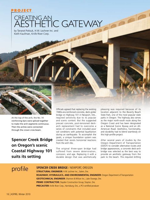
PROJECTCREATING ANAESTHETIC GATEWAYby Tanarat Potisuk, H.W. Lochner Inc. andKeith Kaufman, Knife River Corp.At the top of the arch, the No. 14reinforcing bars were spliced togetherto make the arch segments continuous.<strong>The</strong>n the arches were connectedthrough the crown cross beam.Spencer Creek <strong>Bridge</strong>on Oregon’s scenicCoastal Highway 101suits its settingOfficials agreed that replacing the existing1940s-era reinforced concrete, deck-girderbridge on Highway 101 in Newport, Ore.,required sensitivity due to its popularand scenic context. But the suggestedprecast concrete, post-tensioned deckarchreplacement had to overcome aseries of constraints that included poorsoil conditions with potential liquefactionduring an earthquake. To accomplish thegoals, a unique foundation system wascreated that resists horizontal reactionsfrom the arch ribs.<strong>The</strong> original three-span bridge hadsuffered from severe deterioration,corrosion, and age. Replacing it with adurable design that was aestheticallypleasing was required because of itslocation adjacent to the Beverly BeachState Park, one of the most popular stateparks in Oregon. <strong>The</strong> highway also servesas the major north-south route along theOregon Coast and has been designatedas a National Scenic Byway and an All-American Road. <strong>Aesthetic</strong>s, functionality,and durability had to blend seamlessly onthis high-profile project.After several years of studies by theOregon Department of Transportation(ODOT) to consider alternative routes andbridge appearances, a concrete deck-archbridge was selected as the best way toprovide an aesthetic gateway from thepark to the beach. This required shiftingprofileSPENCER CREEK BRIDGE / NEWPORT, OREGONSTRUCTURAL ENGINEER: H.W. Lochner Inc., Salem, Ore.ROADWAY, HYDRAULICS, AND ENVIRONMENTAL ENGINEER: Oregon Department of TransportationGEOTECHNICAL ENGINEER: Shannon & Wilson Inc., Lake Oswego, Ore.PRIME CONTRACTOR: Slayden Construction Group, Stayton, Ore.PRECASTER: Knife River Corp., Harrisburg, Ore., a PCI-certified producer16 | ASPIRE, Winter 2010
A precast concrete design was selected due tothe sensitive environment at the bridge site.<strong>The</strong> new Spencer Creek <strong>Bridge</strong> featuressix continuous spans supported by threeconcrete arch ribs. <strong>The</strong> bridge replaced a1940s bridge and had to blend with thescenic landscape surrounding it.part of the highway about 50 ft to theeast to accommodate the new bridge. <strong>The</strong>majority of the roadway shift was locatedat the south end of the bridge. <strong>The</strong> bridgespan over the creek was lengthened tomove the bridge foundation further awayfrom the creek.Precast <strong>Concrete</strong> Selected<strong>The</strong> new Spencer Creek <strong>Bridge</strong> is 210 ftlong and 51.3 ft wide. <strong>The</strong> superstructureconsists of 35-ft-long spans. Four spansare supported on columns over the arch.<strong>The</strong> two end spans fit between the bentcolumns over the arch support and theabutments. <strong>The</strong> arch spans 140 ft andconsists of three parallel ribs with aconstant width of 3.5 ft and a depth thatvaries from 4.5 ft to 3.25 ft.Due to the sensitive environment atthe bridge site, precast concrete waschosen for the main structural members,including the arches and beams for thesuperstructure. That approach allowed theamount of falsework and formwork to bereduced, minimizing the environmentalimpact. <strong>The</strong> precast concrete fabricatorsin the area also were considered to beable to provide better quality products forthis coastal region than could be achievedwith cast-in-place concrete construction.Each of the three arch ribs consists of twoprecast concrete arch rib segments castat a plant in Harrisburg, Ore. <strong>The</strong>y weredelivered to the construction site andconnected at the crown with a crossbeamclosure pour. Each arch segment was 70 ftlong, weighed 160 kips, and contained28 No. 14 longitudinal reinforcing bars. Inaddition, the arch segments were posttensionedto prevent cracking during theshipment as well as to control cracking inservice.Stainless SteelReinforcement UsedIn accordance with the ODOT <strong>Bridge</strong>Design and Drafting Manual (BDDM),all concrete was required to be highperformanceconcrete, while stainlesssteelreinforcement was required inthe concrete decks and crossbeams forbridges in the coastal area. This includedall reinforcing bars extending into theconcrete deck. As a result, stainlesssteel was specified for stirrups in theprecast slabs. <strong>The</strong>se bars met the UnifiedNumbering System (UNS) designationS31803, AISI Type 2205, Grade 75.Isolation between different alloys (stainlessand black steel) was performed accordingto ODOT specifications.Rather than transportupright as originallyplanned, the precastconcrete arches weredelivered in their castingposition to avoid difficultyin transporting themthrough some of the sharpturns on the highway.SIX-SPAN BRIDGE ON A PRECAST CONCRETE ARCH / OREGON DEPARTMENT OF TRANSPORTATION, OWNERPOST-TENSIONING CONTRACTOR: AVAR Construction Systems Inc., Fremont, Calif.REINFORCING BAR SUPPLIER: Dixon Steel & Supply Company, Roseburg, Ore.BRIDGE DESCRIPTION: Six-span bridge (including two approach spans) 210 ft long, 51.3 ft wide with continuous spans supported by three precastconcrete arch ribs. Each span is 35 ft long and comprises 12 precast, prestressed concrete slabs with a composite cast-in-place concrete deck.BRIDGE CONSTRUCTION COST: $19.5 millionASPIRE, Winter 2010 | 17
1.2.3.<strong>The</strong> precaster’s recommendations duringpreliminary design included limiting thearch rib’s weight of each segment to140 kips. However, due to the amountof reinforcement required in the archsegments the weight reached 160 kips. Tohandle the arch-rib segments in the plant,the arch casting form was strategicallypositioned so two travel lifts could nestand lift in tandem.<strong>The</strong> precaster also worked with thereinforcing bar supplier to provide longerthan typical length bars. This avoidedthe need to splice bars within the archsegments, which would have added timeand complexity. Rather than the typical60-ft-long bars, the supplier fabricated70-ft-long pieces.Securing the longitudinal No. 14 reinforcementwithin the complex steel cageof reinforcing bars also posed a challenge.Typically, the stirrups would be tied intoposition and the No. 14 bars threadedthrough by hand. But the grid was tootight to allow that to be accomplishedsafely and efficiently. Instead, a woventube that constricts as it’s pulled wasplaced over the end of each bar and thenpulled through to the opposite end witha winch. This approach worked efficientlyand provided better safety than workingwith the bars by hand.(Photos 1-3) Upon arrival at the site,the precast concrete arches were rolledinto lifting position on precast concreteblocks that used the half-arches’ centerof gravity to provide the rotating force.Arches Needed SpecialHandling<strong>The</strong> arch segments were cast on theirside. <strong>The</strong>y were originally planned to beshipped on their bottom edge—in theirfinal resting position. But the precasterdetermined that this position would makethe arch segments difficult to transportthrough some of the sharp turns alongthe highway. Instead, the arch segmentswere redesigned to be shipped flat inthe as-cast position. This required specialequipment to handle the segments,necessitating special lifts that were builtinto the sides of the arch segments formaneuvering at the site.Upon arrival at the bridge site, thearch segments had to be rolled fromtheir shipping position into the properalignment for erection. To avoid siteliftingexpenses and time, a stack ofprecast concrete blocks was created atthe site to serve as a base for rotatingthe arch segments. <strong>The</strong> half-arches’ rollaxis was offset from the center of gravity,so the arch segments could be pickedhorizontally from the truck and set withthe center of the arch on the blocks.As the weight of the arch segment wastransferred to the block support, theywould roll into the proper position forfinal lifting and setting. Sand bags wereset over the entire top of the blocks toprotect the components as they rolled.Connecting the two segments of thearch segments also posed challenges.<strong>The</strong> bottom portions were set in a 3½-in.-deep socket, after which it wasenclosed by a 3.5-ft-deep cast-in-place,reinforced concrete block. To make thearch segments continuous, the No. 14reinforcing bars extending from the topend of each segment were connectedusing metal-filled mechanical splicesbefore placing concrete. <strong>The</strong> splicesprovided tolerance for adjusting thelongitudinal rebar alignments whileretaining the necessary strength.Precast, prestressed concrete voidedslabs made continuous for live load weredesigned for the bridge superstructure.Prestressing strands extending from theprecast slab ends were hooked at bents toprovide continuity between the slabs. <strong>The</strong>cross-members connecting the three archcrowns also served as supports for theprecast concrete slabs.Soil Creates ChallengesSoil in the area consisted of alluviumdeposits of silty-sand, clayey-silt, andorganic debris. <strong>The</strong>se are generally notsuitable for laterally supporting an archbridge. In addition, there were challengeswith anticipated extreme scour andthe sensitive environment surroundingSpencer Creek that had to be addressed.A foundation system was designed usinggrouped, 6-ft-diameter drilled shaftsembedded in bedrock to support thearches and the mechanically stabilizedearth (MSE) walls for the approachembankments. Both provide goodperformance during seismic events.A unique feature was added to thefoundation system by attaching horizontaldeadman anchors and struts to the drilledshaft caps. <strong>The</strong> anchors and struts wereburied beneath the 40-ft-high MSE wallbackfill. <strong>The</strong> deadman-anchor systemwas jacked into the MSE wall fill, usingthe developing passive earth resistanceas the lateral support for the arches. Thisstrengthening method allowed the archesto be set on the weak soil while providingthe drilled shafts with additional resistanceto withstand the horizontal forces.<strong>The</strong> high-performance precast concreteand stainless steel reinforcement werespecified to increase life expectancy of thenew Spencer Creek <strong>Bridge</strong>. <strong>The</strong> designminimized impact to the environmentallysensitive creek and provided an aestheticallypleasing structure. <strong>The</strong> bridge hasbeen well-received by the community.During construction, many local citizenswould watch the arches being created andcomment to the construction team on thebridge’s pleasing appearance.____________Tanarat Potisuk is a structural designengineer at H.W. Lochner Inc. in Salem,Ore., and Keith Kaufman is the chiefengineer at Knife River Corp. in Harrisburg,Ore.For more information on this or otherprojects, visit www.aspirebridge.org.18 | ASPIRE, Winter 2010
training fortraining fortodaythe futureeducation makes a differenceTODAY’S WORKFORCE: PCI Quality Schools<strong>The</strong> PCI QC Schools provide knowledge; networking; and an experience that canimmediately improve performance, quality, safety, and efficiency. <strong>The</strong>se schools providevaluable benefits for all of your employees. Invest in quality and improve yourbottom line. Register today! For more information and the 2010 schedule, visit:www.pci.org/schoolsFUTURE ENGINEERS: Student “Big Beam” Competitionand PCI invite students and members to participate in the EngineeringStudent Design Competition for the 2009–10 academic year. This is ahands-on opportunity for student teams to work with a PCI-Certified Producer Memberto build a precast concrete beam. <strong>The</strong> beams will be tested and prizes awardedfor best performance in several areas. Reach out to a university today!Applications are due by March 15, 2010, and test reports are dueby June 14, 2010, at PCI headquarters.For more information and official entry forms, visit:www.pci.org/bigbeamfor more information contact Alex Morales: amorales@pci.org or (312) 360-3219209 West Jackson Boulevard I Suite 500 I Chicago, IL 60606Phone: 312-786-0300 I Fax: 312-786-0353 I www.pci.orgMKT09-1560HALF.indd 1When Measurements MatterWhat percentage of error can you afford?12/11/09 10:49:06 AMWEIGHTLIMIT53TONSAt Campbell Scientific, we design rugged,stand-alone data acquisition systems for anysize of bridge. For long-term dynamic or staticmonitoring, our systems will provide you withaccurate decision-making data.(435) 750-9692www.campbellsci.com/bridgesASPIRE, Winter 2010 | 19
SPENCER CREEK BRIDGE / NEWPORT, OREGONSpencer Creek <strong>Bridge</strong>Looking NE at sunset.Web | ASPIRE, Winter 2010
SPENCER CREEK BRIDGE / NEWPORT, OREGONPrecast concrete fascia panels are shown being lowered into place along the sides of the bridgeto add a smooth face to the superstructure.Two halves of each precast concrete arch were set into sockets at the foundationand connected with a large cast-in-place concrete blocks.ASPIRE, Winter 2010 | Web
SPENCER CREEK BRIDGE / NEWPORT, OREGON<strong>The</strong> precast arches were shipped on their side and rotated on a speciallymade pedestal to prepare them for lifting into place.Web | ASPIRE, Winter 2010
SPENCER CREEK BRIDGE / NEWPORT, OREGONSpecial lifting hookswere cast into the sidesof the precast concretearches to aid inhandling themprior to rotation.Sand bags were set aroundthe top of the precastconcrete blocks to protectthe components as theyrolled into the liftingposition.ASPIRE, Winter 2010 | Web


