- Page 1:
English 1/2006The Profile System
- Page 5 and 6:
Table of contentsArticle number gro
- Page 7 and 8:
Symbols, Abbreviations, Special cha
- Page 9 and 10:
Numerical key for articles1.03Profi
- Page 11 and 12: 1.04Summary: Profilesofilesofiles (
- Page 13 and 14: Summary: Special profiles1.05Profil
- Page 15 and 16: Profile group 20 mm, H-slot, P (pla
- Page 17 and 18: Profile group 20 mm, F-slot, P (pla
- Page 19 and 20: Profile group 30 mm, F-slot, P (pla
- Page 21 and 22: Profile group 30 mm, F / E4-slot, P
- Page 23 and 24: Profile group 40 mm, E3-slot, P (pl
- Page 25 and 26: Profile group 40 mm, E3-slot, P (pl
- Page 27 and 28: Profile group 40 mm, E3-slot, P (pl
- Page 29 and 30: 271
- Page 31 and 32: Profile group 45 mm, E4-slot, P (pl
- Page 33 and 34: Profile group 50 mm, E4-slot, P (pl
- Page 35 and 36: Special profiles, P (plain)1.11heav
- Page 37 and 38: Profile group 30 mm, F-slot (with g
- Page 39 and 40: Profile group 40 mm, E3-slot (with
- Page 41 and 42: Profile group 40 mm, E3-slot (with
- Page 43 and 44: 411
- Page 45 and 46: Profile group 50 mm, E4-slot (with
- Page 47 and 48: Panel profiles 40, E3-slot, P (plai
- Page 49 and 50: Roller profiles (plain)5.11heavy1De
- Page 51 and 52: Telescopic profiles, E3-slot (plain
- Page 53 and 54: Special profiles1.19Angle profilesT
- Page 55 and 56: Special profiles1.19TubesTechnical
- Page 57 and 58: Special profiles1.19Slide-slot prof
- Page 59 and 60: Special profiles1.19E-trunking prof
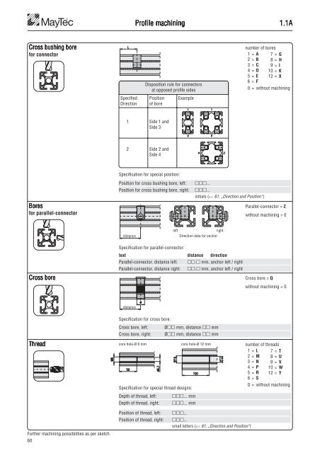
- Page 61: Profile machining1.1ASaw cutSaw cut
- Page 65 and 66: Profile machining1.1BCoding example
- Page 67 and 68: Technical data1.1CExtruded profilea
- Page 69 and 70: Technical data1.1CTo determine the
- Page 71 and 72: Profile selection range1.1DDesignPG
- Page 73 and 74: Profile selection range1.1DDesignPG
- Page 75 and 76: Profile applications1.1E.02Slot pla
- Page 77 and 78: Profile applications1.1E.02Slot pla
- Page 79 and 80: Profile applications1.1E.04U-Profil
- Page 81 and 82: Profile applications1.1E.06Profiles
- Page 83 and 84: Profile applications1.1E.06Profiles
- Page 85 and 86: Connection System1.22SimpleQuickEco
- Page 87 and 88: Connectors - Examples1.2MayTec conn
- Page 89 and 90: Summary: Connectors (with machining
- Page 91 and 92: Connectors: Manufacture a connectio
- Page 93 and 94: Connectors for profiles with core h
- Page 95 and 96: Connectors for profiles with core h
- Page 97 and 98: Connectors for profiles with core h
- Page 99 and 100: Connectors for profiles with core h
- Page 101 and 102: Connector - Cross bushings1.2BDrill
- Page 103 and 104: Connector components1.2CConnector c
- Page 105 and 106: Connector components1.2CSingle part
- Page 107 and 108: Connector components1.2CPG 45 PG 50
- Page 109 and 110: Connectors - Special cases1.2DExten
- Page 111 and 112: Connectors - Special cases1.2DSE-Co
- Page 113 and 114:
Connectors - Special cases1.2DST-Co
- Page 115 and 116:
Connectors - Special cases1.2DBayon
- Page 117 and 118:
Connectors - Special cases1.2DBayon
- Page 119 and 120:
Connectors - Special cases1.2DClamp
- Page 121 and 122:
Connection possibilities for 0-slot
- Page 123 and 124:
Connection possibilities for 0-slot
- Page 125 and 126:
Connection possibilities for 0-slot
- Page 127 and 128:
Connection possibilities - Special
- Page 129 and 130:
Strength values for profile connect
- Page 131 and 132:
Connection elements1.29Anti-twist d
- Page 133 and 134:
Connection elements1.29Clamping lev
- Page 135 and 136:
Summary: Accessories1.3-1.9Fastenin
- Page 137 and 138:
Fastening elements1.31Threaded plat
- Page 139 and 140:
Fastening elements1.31Threaded plat
- Page 141 and 142:
Fastening elements1.32T-Nutsfor sub
- Page 143 and 144:
Fastening elements1.33Spring-nutsfr
- Page 145 and 146:
Fastening elements1.34Rhomboid T-sl
- Page 147 and 148:
Fastening elements1.35Threaded inse
- Page 149 and 150:
Fastening elements1.35Press-fit thr
- Page 151 and 152:
Installation accessories1.41Cover p
- Page 153 and 154:
Installation accessories1.41Combina
- Page 155 and 156:
Installation accessories1.41Sliding
- Page 157 and 158:
Installation accessories1.41Guide p
- Page 159 and 160:
Installation accessories1.41Wedge p
- Page 161 and 162:
Installation accessories1.41Sponge
- Page 163 and 164:
Installation accessories1.41Framing
- Page 165 and 166:
Installation accessories1.41Rubber
- Page 167 and 168:
Installation accessories1.42for pro
- Page 169 and 170:
Installation accessories1.42Cover p
- Page 171 and 172:
Installation accessories1.43Radius
- Page 173 and 174:
Installation accessories1.43Radius
- Page 175 and 176:
Installation accessories1.44Hand ad
- Page 177 and 178:
Installation accessories1.44Adjusta
- Page 179 and 180:
Installation accessories1.44Adjusta
- Page 181 and 182:
Installation accessories1.44Adjusta
- Page 183 and 184:
Installation accessories1.44Base fo
- Page 185 and 186:
Installation accessories1.4445×45,
- Page 187 and 188:
Installation accessories1.44Floor m
- Page 189 and 190:
Installation accessories1.44Base an
- Page 191 and 192:
Installation accessories1.45Swivel
- Page 193 and 194:
Installation accessories1.45Locking
- Page 195 and 196:
Installation accessories1.46Angles
- Page 197 and 198:
Installation accessories1.4628×28D
- Page 199 and 200:
Installation accessories1.4638×76D
- Page 201 and 202:
Installation accessories1.4674×76D
- Page 203 and 204:
Installation accessories1.46Angles
- Page 205 and 206:
Installation accessories1.46 - 1.47
- Page 207 and 208:
Installation accessories1.47Floor m
- Page 209 and 210:
Installation accessories1.47Connect
- Page 211 and 212:
Installation accessories1.47Eye-bol
- Page 213 and 214:
Installation accessories1.4845°Des
- Page 215 and 216:
Installation accessories1.48Corner
- Page 217 and 218:
Pneumatic accessories1.51Pneumatic
- Page 219 and 220:
Pneumatic accessories1.52Pneumatic
- Page 221 and 222:
Pneumatic accessories1.55Pneumatic
- Page 223 and 224:
Additional accessories1.61Handles l
- Page 225 and 226:
Additional accessories1.61Handle sy
- Page 227 and 228:
Additional accessories1.61Grab hand
- Page 229 and 230:
Additional accessories1.62Lift-off
- Page 231 and 232:
Additional accessories1.62Lift-off
- Page 233 and 234:
Additional accessories1.62HingesApp
- Page 235 and 236:
Additional accessories1.62HingesApp
- Page 237 and 238:
Additional accessories1.62Hinge40×
- Page 239 and 240:
Additional accessories1.62Hinge 50
- Page 241 and 242:
Additional accessories1.62Type Cpro
- Page 243 and 244:
Additional accessories1.62countersi
- Page 245 and 246:
Additional accessories1.6320×20Des
- Page 247 and 248:
Additional accessories1.64Mounting
- Page 249 and 250:
Additional accessories1.64Mounting
- Page 251 and 252:
Additional accessories1.64Mounting
- Page 253 and 254:
Additional accessories1.64Mounting
- Page 255 and 256:
Additional accessories1.64Sealing w
- Page 257 and 258:
Additional accessories1.65Bullet ca
- Page 259 and 260:
Additional accessories1.65Lock GD-Z
- Page 261 and 262:
Additional accessories1.65Cylinder
- Page 263 and 264:
Additional accessories1.65Cylinder
- Page 265 and 266:
Additional accessories1.65Mortise d
- Page 267 and 268:
Additional accessories1.65Door hand
- Page 269 and 270:
Additional accessories1.65Profile m
- Page 271 and 272:
Additional accessories1.65Olive ins
- Page 273 and 274:
Additional accessories1.66Roller 39
- Page 275 and 276:
Additional accessories1.66Roller fa
- Page 277 and 278:
Additional accessories1.66Roller fa
- Page 279 and 280:
Additional accessories1.66Mounting
- Page 281 and 282:
Additional accessories1.66Roller fi
- Page 283 and 284:
Additional accessories1.66Runnerfor
- Page 285 and 286:
Additional accessories1.67Slot roll
- Page 287 and 288:
Additional accessories1.67Clampingf
- Page 289 and 290:
Additional accessories1.67Eco-Slide
- Page 291 and 292:
Additional accessories1.67Eco-Slide
- Page 293 and 294:
Additional accessories1.68Hanging b
- Page 295 and 296:
Electrical accessories1.70Potential
- Page 297 and 298:
Electrical accessories1.71Cable and
- Page 299 and 300:
Electrical accessories1.71Installat
- Page 301 and 302:
Electrical accessories1.73Safety sw
- Page 303 and 304:
Electrical accessories1.73Safety in
- Page 305 and 306:
Electrical accessories1.73Safety in
- Page 307 and 308:
Electrical accessories1.73Safety in
- Page 309 and 310:
Electrical accessories1.74Electrica
- Page 311 and 312:
Electrical accessories1.74Rocker sw
- Page 313 and 314:
Electrical accessories1.75Electrica
- Page 315 and 316:
Electrical accessories1.75E-trunkin
- Page 317 and 318:
Panel elements1.81Corner element 33
- Page 319 and 320:
Panel elements1.82Panel elementsApp
- Page 321 and 322:
Panel elements1.85Alu-plastic compo
- Page 323 and 324:
Panel elements1.88Wire net, AluAppl
- Page 325 and 326:
Screws1.90Button head screwsApplica
- Page 327 and 328:
Tools1.98Tx screw driverTechnical d
- Page 329 and 330:
Tools1.99Drill jigsfor profiles wit
- Page 331 and 332:
Tools1.99Drill jigsfor profiles wit
- Page 333 and 334:
Tools - Special cases1.99Toolsfor p
- Page 335 and 336:
Tools1.99Screw tapsfor aluminium ma
- Page 337 and 338:
CAD Library1.A2MayTec ec 3D Library
- Page 339 and 340:
Conversion tables1.B2Metric / U.S.
- Page 341 and 342:
Subject indexConnection with DIN-Sc
- Page 343 and 344:
Subject indexwith core hole-Ø6 for
- Page 345 and 346:
Subject indexSuspended doors ......
- Page 347 and 348:
MayTec GmbH plant in DachauSmall pa