Installation Instructions for All S&S Pistons - Zodiac
Installation Instructions for All S&S Pistons - Zodiac
Installation Instructions for All S&S Pistons - Zodiac
- No tags were found...

You also want an ePaper? Increase the reach of your titles
YUMPU automatically turns print PDFs into web optimized ePapers that Google loves.
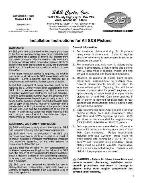
Instruction 51-1028Revised 4-5-02Copyright®, 2002by S&S Cycle, Inc.<strong>All</strong> rights reserved. Printed in the U.S.A.S&S Cycle, Inc.14025 County Highway G Box 215Viola, Wisconsin 54664Phone: 608-627-2080 • Fax: 608-627-1488Technical Service Phone: 608-627-TECH (8324)Technical Service Email: sstech@sscycle.comWebsite: www.sscycle.comBecause every industry has a leader<strong>Installation</strong> <strong>Instructions</strong> <strong>for</strong> <strong>All</strong> S&S <strong>Pistons</strong>WARRANTY:<strong>All</strong> S&S parts are guaranteed to the original purchaserto be free of manufacturing defects in materials andworkmanship <strong>for</strong> a period of twelve (12) months fromthe date of purchase. Merchandise that fails to con<strong>for</strong>mto these conditions will be repaired or replaced at S&S'soption if the parts are returned to us by the purchaserwithin the 12 month warranty period or within 10 daysthereafter.In the event warranty service is required, the originalpurchaser must call or write S&S immediately with theproblem. Some problems can be rectified by atelephone call and need no further course of action.A part that is suspect of being defective must not bereplaced by a Dealer without prior authorization fromS&S. If it is deemed necessary <strong>for</strong> S&S to make anevaluation to determine whether the part was defective,a return authorization number must be obtained fromS&S. The parts must be packaged properly so as to notcause further damage and be returned prepaid to S&Swith a copy of the original invoice of purchase and adetailed letter outlining the nature of the problem, howthe part was used and the circumstances at the time offailure. If after an evaluation has been made by S&Sand the part was found to be defective, repair,replacement or refund will be granted.ADDITIONAL WARRANTY PROVISIONS:(1) S&S shall have no obligation in the event an S&Spart is modified by any other person or organization.(2) S&S shall have no obligation if an S&S partbecomes defective in whole or in part as a result ofimproper installation, improper maintenance, improperuse, abnormal operation, or any other misuse ormistreatment of the S&S part.(3) S&S shall not be liable <strong>for</strong> any consequential orincidental damages resulting from the failure of an S&Spart, the breach of any warranties,the failure to deliver,delay in delivery, delivery in non-con<strong>for</strong>ming condition,or <strong>for</strong> any other breach of contract or duty between S&Sand a customer.(4) S&S parts are designed exclusively <strong>for</strong> use inHarley-Davidson motorcycles. S&S shall have nowarranty or liability obligation if an S&S part is used inany other application.General In<strong>for</strong>mation1. For maximum piston and ring life, fit pistonsusing close fit dimensions. Close fit requiresabsolute adherence to new engine break-in asdescribed on page 4.2. For immediate drag strip use, fit pistons usingloose fit dimensions. Break in rings and pistonswith 50 easy miles if possible. Piston and ringlife will be reduced with loose fit dimensions.3. Measure all pistons at widest point acrossthrust face, perpendicular to wristpin hole.Several measurements should be taken tolocate widest point. Typically, this will be atbottom of piston skirt <strong>for</strong> pre-V 2 engines, andapproximately 1 ⁄2" below level of wristpin hole inpistons <strong>for</strong> V 2 and Twin Cam style engines. Ifpre-V 2 piston is notched <strong>for</strong> placement in rearcylinder, use measurement directly above notch<strong>for</strong> skirt measurement.4. S&S recommends #220-#280 grit stone <strong>for</strong> finalhoning of stock bore and Sidewinder , S&STwin Cam and SSW+ big bore cylinders. #320grit stone is recommended <strong>for</strong> engines usingS&S 92-4500, 92-4510, or 92-4520 pistons.5. Follow procedure recommended in H-D servicemanual <strong>for</strong> boring and honing stock bore V 2 andTwin Cam cylinders. Follow instructionsincluded with S&S Cylinder Torque Plate Kitwhen boring and honing S&S 3 5 ⁄8" or 4", 4 1 /8"bore V 2 and Twin Cam style cylinders. Torqueplates must be used to simulate compressivestress in an assembled engine. Cylinders willdistort if torque plates are not used.CAUTION - Failure to follow instructions andper<strong>for</strong>m required clearancing, installation and/orbreak-in procedures may result in damage topistons and/or other engine components notcovered under warranty.1
Piston Fitment ChartPiston Series Close Fit Loose FitPiston Series Close Fit Loose Fit292-1000 (N/A) .0015" to .002" .003" to .004"92-1010 (N/A) .0015" to .002" .003" to .004"92-1020 (N/A) .0015" to .002" .003" to .004"92-1030 (N/A) .015" to .002" .003" to .004"92-1040 (N/A) .0015" to .002" .003" to .004"92-1050 (N/A) .0015" to .002" .003" to .004"92-1060 .0023" to .0025" .0035" to .0045"92-1070 .0023" to .0025" .0035" to .0045"92-1080 .0023" to .0025" .0035" to .0045"92-1090 †92-1100 .0023" to .0025" .0035" to .0045"92-1110 .0023" to .0025" .0035" to .0045"92-1120 .0023" to .0025" .0035" to .0045"92-1130 .0023" to .0025" .0035" to .0045"92-1200 .002" to .0025" .0032" to .0045"92-1210 .002" to .0025" .0032" to .0045"92-1400 .002" to .0025" .0032" to .0045"92-1410 .002" to .0025" .0032" to .0045"92-1420 .002" to .0025" .0032" to .0045"92-1430 .002" to .0025" .0032" to .0045"92-1436 .002" to .0025" .0032" to .0045"92-1500 .0008" to .0013" .002" to .0025"92-1510 .0008" to .0013" .002" to .0025"92-1520 .0008" to .0013" .002" to .0025"92-1530 .0008" to .0013" .002" to .0025"92-1540 .0008" to .0013" .002" to .0025"92-1550 .002" to .0025" .0032" to .0045"92-1556 .002" to .0025" .0032" to .0045"92-1560 .002" to .0025" .0032" to .0045"92-1600 *** .0015" to .002" .0025" to .0035"92-1620 * .002" to .003" .0035" to .004"92-1630 *** .0015" to .002" .0025" to .0035"92-1630 * .002" to .003" .0035" to .004"92-1640 *** .0015" to .002" .0025" to .0035"92-1640 * .002" to .003" .0035" to .004"92-1800 *** .0025" to .003" .0045" to .0055"92-1800 * .0035" to .004" .005" to .006"92-1830 * .0035" to .004" .005" to .006"92-1840 * .0035" to .004" .005" to .006"92-1900 .0015" to .002" .003" to .004"92-1910 .0015" to .002" .003" to .004"92-1930 .0015" to .002" .003" to .004"92-1940 .0015" to .002" .003" to .004"92-2000 .0015" to .002" .003" to .004"92-2010 .0015" to .002" .003" to .004"92-2020 .0015" to .002" .003" to .004"92-2030 .0015" to .002" .003" to .004"92-2040 .0015" to .002" .003" to .004"92-2050 .0015" to .002" .003" to .004"92-2400 .0008" to .0013" .002" to .0025"92-2420 .0008" to .0013" .002" to .0025"92-2440 .0008" to .0013" .002" to .0025"92-2460 .0008" to .0013" .002" to .0025"92-2500 .002" to .0025" .003" to .0035"92-2510 .002" to .0025" .003" to .0035"92-2600 .002" to .0025" .003" to .0035"92-2610 .002" to .0025" .003" to .0035"92-2700 *** .0015" to .002" .0025" to .0035"92-2720 * .002" to .003" .0035" to .004"92-2730 * .002" to .003" .0035" to .004"92-2800 *** .0025" to .003" .0045" to .0055"92-2800 * .0035" to .004" .005" to .006"92-2900 * .0035" to .004" .005" to .006"92-3500 .003" to .0035" .0045" to .0055"92-3700 .003" to .0035" .0045" to .0055"92-4000 † .0025" to .003" .0045" to .0055"92-4010 † .0025" to .003" .0045" to .0055"92-4020 .0025" to .003" .0045" to .0055"92-403092-4300 †92-4310 †92-4400 †92-4410 †92-4420 †92-4500 † .008" to .010" .012"- up92-4510 † .008" to .010" .012"- up92-4520 † .008" to .010" .012"- up92-4530 †92-4535 †92-4800 †92-4805 †92-4810 †92-4815 †92-4950 †92-4955 †92-4960 †92-4962 †92-4965 †92-4970 †*** - With Slotted oil ring groove. * - With holed oil ring groove. (N/A) - Not available.† - Racing pistons. Fitment depends on what type of cylinder customer is using.
Piston <strong>Installation</strong>1. Piston Series #92-1500, #92-1510, #92-1530, #92-1540,#92-1600, #92-1620, #92-1630, #92-1640, #92-2400,#92-2420, #92-2440, #92-2460, #92-2700, #92-2720and #92-2730 have offset wristpins and must beinstalled with dimple in piston dome toward right or camside of engine. Piston Series #92-1060, #92-1070 and#92-1080, #92-1210, #92-1550, #92-1556, #92-1560also have offset wristpins and must be installed withsymbol ➞CAM toward right or cam side of engine.2. Piston Series #92-3500, #92-3700, #92-4300 and#92-4310 have larger intake valve reliefs which mustbe installed toward intake valves or middle of engine.3. Most other pistons have no special features. Theycan be installed as desired unless piston skirt haspiston-to-piston clearance bevel on one side. Insuch case, bevel must face center of engine. If onlyone piston has bevel, it will be <strong>for</strong> rear cylinder. See#4 immediately below.4. Some piston sets have all piston-to-piston clearancemachined into rear piston. In such cases rear pistonmust be installed with bevel or notch toward front. Ifdimple is present, piston must be installed withdimple in correct position.5. Check all installations <strong>for</strong> minimum of .060"clearance between pistons at closest point nearbottom of stroke.6. Check all installations <strong>for</strong> minimum of .060"clearance between pistons and flywheels at bottomof stroke. New 4 5 ⁄8" stroke stock bore andSIDEWINDER pistons should come with correctpiston to flywheel clearance. Replacement pistonsmay or may not have adequate clearance. Comparereplacement pistons with ones being replaced andmake corrections accordingly.NOTE - In all cases it is the engine builder'sresponsibility to confirm proper clearances whenassembling an engine. This is especially critical withper<strong>for</strong>mance components such as higher compressionpistons and high lift camshafts. In addition toclearances mentioned, .060" valve-to-piston clearancemust be confirmed.CAUTION - Failure to establish properclearances can result in severe engine damage notcovered under warranty.Wristpin Retainer <strong>Installation</strong>NOTE - Thoroughly clean wristpin be<strong>for</strong>e installation,paying particular attention to bore. Pass clean, lint-freecloth back and <strong>for</strong>th through wristpin bore several timesto insure removal of contaminants.1. If wristpin clips are used, insure that groove in pistonis free of burrs and <strong>for</strong>eign matter.2. Round "wire" style clips identical to and interchangeablewith stock H-D V 2 clips require wristpins with speciallychamfered ends. Install wire clips using procedurerecommended by H-D. End of clip must rest over notchin piston below wristpin hole to allow removal of clip infuture. Be sure clip is fully seated in groove.NOTE - Round "wire" style clip ends must be deburredbe<strong>for</strong>e installation.3. "Tru-Arc" style clips should be installed with propertool. Clips should not be used with wristpins havingchamfer on end greater than 1 ⁄64". Install clip withopen side facing downward and sharp edge of clip tooutside of wristpin hole away from wristpin. Be sureclip is fully seated in groove.4. "Spiral-Loc" style clips are installed by slowlyworking clip into wristpin hole using thumb nail, smallscrewdriver or awl in circular turning motion. Onceentire clip is in hole, push end of clip into groove,followed by rest of clip. Be sure clip is fully seated ingroove.5. Teflon wristpin buttons must be used only in pistonswhere buttons are fully supported in wristpin hole.Buttons are used in place of and not in conjunctionwith conventional wristpin clips. Recommendedwristpin endplay is .010" to .060" and is determinedby subtracting length of wristpin with button on eachend from finished cylinder bore.To make fitting easier, S&S buttons come in fourwidths. "A" buttons are thinnest and "D" buttons arethickest. Use two A buttons, Part #94-9251, <strong>for</strong> boresizes 3 7 ⁄16" std. to 3 7 ⁄16" +.040, two B buttons, Part#94-9252, <strong>for</strong> bore sizes 3 7 ⁄16" +.050 to 3 7 ⁄16" + .090,two C bottoms. Part #94-9258, <strong>for</strong> bore sizes 3 5 ⁄8"std. to 3 5 ⁄8" +.030, and two D buttons, Part #94-9259,<strong>for</strong> bore sizes 3 5 ⁄8" +.040 to 3 5 ⁄8" +.070.6. Special notched aluminum buttons are supplied withPiston Series #92-3500 and #92-3700. Wheninstalled, notch simulates oil ring groove and helpssupport oil ring. Buttons should not protrude beyondring land diameter when in place3
Ring <strong>Installation</strong>1. Ring widths on some piston series have changedfrom time to time. Part numbers of rings originallysupplied with pistons should be recorded <strong>for</strong> futurereference in the event replacement rings arerequired.2. The majority of ring kits presently supplied by S&Scontain a moly faced top ring, a cast, reverse torsionsecond ring, and a three piece oil ring. This may beconfirmed as follows:A. Top compression ring has a gray finish that isrelatively light in color, and may or may not havea slight bevel along the inner edge. It has no dotor other identifying mark. The light color can bestbe recognized by comparing compression ringsto each other beneath a good light. Install lightcolored ring without dot in top groove, bevel up.If there is no bevel, ring can be installed eitherside up.B. Second compression ring has a darker,charcoal gray finish and slight bevel along innersurface. This ring has a dot. See Figure A.Install in second or middle groove with dot up.C. Oil rings are three piece type with two rails andone expander. Do not shorten expander <strong>for</strong> anyreason! <strong>Installation</strong> is straight<strong>for</strong>ward with onerail placed above expander, other rail belowexpander. Rails may be shortened to correctgap, but burrs must be carefully removed.NOTE - In some cases, same expander is used <strong>for</strong>several bore sizes. Oversize rings will not necessarilyhave a larger expander.●●CAUTIONS:Failure to remove burrs may cause enginedamage.Incorrect installation of rings may result in poorper<strong>for</strong>mance, excessive oil consumption orengine damage.3. For ring kits in which Section #2 above does notapply, compression rings may be of plain cast irontype, chrome faced cast iron type, moly faced casttype or chrome type.A. The most common combinations are:1. Two chrome faced cast rings2. One chrome faced cast ring & one plain cast ring.3. One moly faced cast ring & one plain cast ring.B. Install as follows:1. Chrome faced or moly faced ring alwaysgoes in top groove2. Plain cast ring usually goes in secondgroove. Plain cast type is usually a reversetorsion ring distinguished by an insidediameter bevel on one side of ring and a"dot" or oversize mark on other side. SeeFigure A. If two cast iron compression ringsare supplied in a set, check to see if one isreverse torsion style ring with dot and bevel.Reverse torsion style ring always goes insecond groove with dot up if present.C. The following rules apply to compression ringidentification and placement. Rules are listed inorder of priority. In other words, if both Rule #2and Rule #4 apply, <strong>for</strong> example, Rule #2 will befollowed and Rule #4 ignored.1. Chrome or moly ring goes in top groove.2. Cast iron regular or reverse torsion ring goesin second groove.3. Any identifying "pip" marks, dots or oversizemarks go to top of piston.4. Ring with one dot goes in top groove, ringwith two dots goes in second groove.5. If both rings are identical and have one dot ortwo dots, either ring can go in either groove.6. If ring has dot and inside diameter bevel, dotgoes to top of piston. See Figure 1.7. If ring has no dot but does have insidediameter bevel, bevel goes to top of piston.See Figure 2.8. If ring has no dots and no bevel, it can goeither way. See Figure 3.4. Ring Gap MeasurementsA. Compression ring end gap on V 2 s with 3 1 ⁄2" boreis .014" to .022".B. End gap on all other compression rings is.016" to .024".C. Oil ring rail end gap on V 2 s with 3 1 ⁄2" bore is.015" to .035".D. Oil ring rail end gap on all others is .015" to .035".E. Compression ring end gap on V 2 s with 4 1 /8" boreis .017" to .025".F. Oil ring rail end gap on V 2 s with 4 1 /8" bore is.015" to .035".4
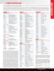
Figure 1 Figure 2 Figure 3NOTE - In certain instances, the next oversize ring setmay be supplied with pistons, <strong>for</strong> example + .060"oversize rings with +.050" pistons. In this case end gapsmust be measured and rings filed as necessary. Endsmust then be carefully deburred.CAUTION - Failure to deburr rings may result inengine damage.Piston Series #92-1210, #92-1550, #92-1556, and #92-1560 have a ring support rail that needs to beinstalled be<strong>for</strong>e any other rings are installed.5. Install ring suppport rail in front piston so that theend gap is toward the rear of the cylinder (90° fromwristpin). Install ring support rail on rear piston sothat the end gap is toward front of the cylinder (90°from wristpin).6. Ring Gap PlacementA. Oil ring1. Expander gap must be in center of thrustface (rear of piston), or 90° from wristpin.2. Bottom rail gap should be approximately 1.5"or 45° to right of expander gap.3. Top rail gap should be approximately 1.5" or45° to left of expander gap.NOTE - Confirm that ends of expander do not overlapduring installation. Properly installed expander willappear larger than piston but will compress whencylinder installed.B. Top compression ring gap should be 135° orapproximately 4 1 ⁄2" to left of oil expander gap.C. Second compression ring gap should be 135° orapproximately 4 1 ⁄2" to right of oil expander gap.Piston Series #92-4500, #92-4510, #92-4520NOTE - Removal of material from underside of pistondome may distort piston slightly causing wrist pin holesto become non-parallel and non-concentric. If material isremoved, wrist pin holes must be rehoned to preventwrist pin binding.CAUTION - Failure to rehone wrist pin holesafter material is removed from dome may result inwrist pin seizure and possible engine damage.If S&S connecting rod set is to be used with S&S racingpistons, Series #92-4500, #92-4510 or #92-4520, thatare equipped with .892" diameter wristpins, wristpinbushings must be pressed out of rods and two 3 ⁄32"diameter holes drilled on each side of I-beam into pinboss. Holes must be as close to parallel with I-beam aspossible. After holes are drilled, wristpin hole of each rodmust be honed to provide .001" running clearance. SeeFigure 4. Rod sets with these modifications per<strong>for</strong>medby S&S can be ordered <strong>for</strong> an additional $25.00 overnormal rod set price.NOTE - S&S offers standard and oversize large diameterwristpins <strong>for</strong> #92-4500, #92-4510, and #92-4520 Seriesracing pistons. Part numbers are: .892" diameter -#94-9260, .893" diameter - #94-9261, .894" diameter -#94-9262.5
Engine Break-In ProcedurePiston Series #92-4300, 92-4310Hone to .001"Running ClearanceDrill 3/32" hole on each sideof I-beam <strong>for</strong> additional oiling.Figure 4Piston Series #92-4300 has a high dome which isapproximately .975" above deck surface, resulting incompression ratio of about 15:1. This piston andcompression ratio are recommended <strong>for</strong> gasolineburning race engines.Piston Series #92-4310 has a slightly lower dome whichis approximately .600" above deck surface, resulting incompression ratio of about 11.5:1. This combination isrecommended <strong>for</strong> fuel engines.#92-4310 piston is essentially #92-4300 piston with.375" removed from top of dome. If compression ratioother than that achieved with #92-4300 or #92-4310piston is desired, up to .375" may be removed fromdome of #92-4300 piston.Corners of dome on #92-4310 Series piston may also beremoved to lower compression, but removing materialfrom top center portion of #92-4310 dome is notrecommended. Dome center is .300" thick, the minimumrequired <strong>for</strong> adequate strength.For reference, difference in dome volume between #92-4300 piston and #92-4310 piston is about 11cc’s.Removal of .225" from dome of #92-4300 piston makesdome height .750,” adding about 5cc’s to combustionchamber volume compared to what it would be with#92-4310 piston.NOTES:● S&S engines are designed <strong>for</strong> high per<strong>for</strong>mance andas such are not as tolerant of inadequate break-in asstock or lower per<strong>for</strong>mance engines. Correct breakinwill assure longer engine life and will preventunnecessary engine damage. Engine damagecaused by improper break-in is not covered underthe S&S warranty.● If new pistons have not been installed, only steps A,B, and C are required.● If new pistons have been installed, all break in stepsare required.A Initial start up. Run engine approximately oneminute at 1250-1750 rpm. DO NOT crackthrottle or subject to any loads during this periodas head gaskets are susceptible to failure at thistime. During this time check to see that oilpressure is normal, that oil is returning to the oiltank, and that no leaks exist.B. Shut off engine and thoroughly check <strong>for</strong> anyleaks or other problems. Let engine cool to thetouchC. After engine has cooled, start up again and allowthe motor to build some heat. Engine should berun no longer than three to four minutes. Whenthe cylinders become warm/hot to the touch(approximately 150°) shut the motor down andlet it cool to room temp. Follow the samecautions as <strong>for</strong> the initial start-up, and continue towatch <strong>for</strong> problems.D. Repeat this procedure 3 or 4 times. Eachsuccessive time it should take slightly longer towarm up and you can increase the temp slightlyeach time (+10°). You can be more liberal eachtime with the rpm, gently vary rpm continuouslyfrom idle up to 2500 rpm in the final cycle. Don’tbe too concerned with final carb settings at thistime because idle speed and mixture cannot becorrectly set until the motor reaches fulloperating temperature. The motor should notreach that temperature during these cycles. Donot allow engine temperature to becomeexcessive. After the motor has cooled to roomtemperature <strong>for</strong> the final time you are ready tostart the 500 mile engine break-in process.*NOTE - Fit wristpins at .0007" to .001.”6
E. The first 50 miles are most critical <strong>for</strong> new ringsand piston break-in. Engine damage is mostlikely to occur during this period. Keep heatdown by not exceeding 2500 rpm. Avoid luggingthe motor, riding in hot weather or in traffic. Varythe engine speed. Do not lug the engine. Werecommend changing the oil at 50 miles.F. The next 500 miles should be spent runningengine no faster than 3500 rpm or 60 mph.Avoid continuous steady speeds, and do not lugthe engine. Vary engine rpm. We recommendchanging the oil again at 500 miles.G. For the balance of the first 1000 miles the motorcan be run in a normal but conservativemanner. You can be more liberal with the rpmrange and motorcycle can be operated atnormal highway speeds. Avoid overheating orputting any hard strain on the engine: no dragracing, dyno runs, excessive speed, trailertowing or sidecar operation.H. After 1000 miles, verify carburetor jetting andadjustment. Change the engine oil. Motorcyclecan now be operated normally.I. Have Fun!CAUTION – Lugging or running engineprematurely at sustained high rpm may result indamage to pistons and other enginecomponents. S&S voids its guarantee if engineis not broken in properly.Safe Riding!Because every industry has a leader7