Installation Notes PASSLOCK I - Ready Remote
Installation Notes PASSLOCK I - Ready Remote
Installation Notes PASSLOCK I - Ready Remote
- No tags were found...

Create successful ePaper yourself
Turn your PDF publications into a flip-book with our unique Google optimized e-Paper software.
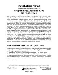
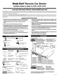
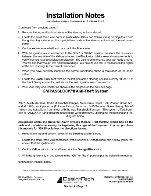
<strong>Installation</strong> <strong>Notes</strong><strong>Installation</strong> <strong>Notes</strong> - Document #113 - Sheet 2 of 3(Continued from previous page...)1. Remove the top and bottom halves of the steering column shroud.2. Locate the small three wire harness (with White, Black and Yellow wires) running down fromthe ignition key cylinder on the top right hand side of the steering column into the instrumentpanel.3. Cut the Yellow wire in half and bare back the Black wire.4. With the ignition key in and turned to the “ON” or “RUN” position, measure the resistancebetween the key side of the Yellow wire and the Black wire. Make several measurements toverify that you have a consistent resistance. You also need to change your test leads around.You will find that you get two different readings. We have found that in most cases the higherof the two readings is the correct resistance.5. When you have correctly identified the correct resistance obtain a resistance of the samevalue.6. Locate the Black “Bulb Test” wire on the left side of the steering column in cavity “D” or “E” ofthe Black 5-way connector, just above the main ignition switch connector.7. Wire your relay and resistor as shown in the diagram on the previous page.GM <strong>PASSLOCK</strong> ® II Anti-Theft System1997+ Malibu/Cutlass, 1998+ Oldsmobile Intrigue, Alero, Buick Regal, 1999 Pontiac Grand Amand all 1998+ truck platforms (Full size Pickup, Suburban, S-10/Sonoma, Blazer/Jimmy, Tahoe/Yukon and Astro/Safari) came out with the new Passlock II system. This system differs fromthat of <strong>PASSLOCK</strong> I and therefore needs to be wired differently utilizing the instructions and thediagram below.DesignTech offers the Universal Alarm Bypass Module (Part #20402) which has all theparts and materials necessary for bypassing this type of theft system. You can purchasethis module for $39.95 or follow the directions below.1. Remove the top and bottom halves of the steering column shroud.2. Locate the small three-wire harnesses (with Red/White, Orange/Black and Yellow wires) thatcome off of the ignition key.3. Cut the Yellow wire in half and bare back the Orange/Black wire.4. With the ignition key in and turned to the “ON” or “Run” position put the vehicle into reverse.continued on the next page...DesignTech disclaims any liability or responsibility arising out of any inaccuracies of this information or use of this information for installations or otherwise.©2003 All Rights ReservedDesignTech International, Inc.DesignTech International, Inc.1-800-337-4468www.designtech-intl.comSection 4 - Page 12