Model 28624TN - Ready Remote
Model 28624TN - Ready Remote
Model 28624TN - Ready Remote

Create successful ePaper yourself
Turn your PDF publications into a flip-book with our unique Google optimized e-Paper software.
<strong>Model</strong> <strong>28624TN</strong><br />
➤Owner’s/Installation Guide<br />
OEM Series
limited lifetime consumer warranty<br />
Directed Electronics (hereinafter "Directed") promises to the original purchaser to repair<br />
or replace with a comparable reconditioned Directed DIY remote start unit if this<br />
Directed DIY remote start unit (hereinafter "Unit"), excluding without limitation, any<br />
remote transmitters or associated accessories, proves defective in materials or workmanship<br />
under normal use for the life of the vehicle which the Unit is originally installed.<br />
During this period, so long as the Unit remained installed in the original vehicle, Directed<br />
will at its option, repair or replace this Unit if it is proved defective in workmanship or<br />
material PROVIDED the Unit is returned to Directed's warranty department at One<br />
Viper Way, Vista, CA 92081, along with $20 postage and handling fee, a bill of sale or<br />
other dated proof of purchase bearing the following information: Date of purchase, name<br />
and location of the merchant who sold the Unit, and product description. This warranty<br />
does not cover labor costs for the removal or reinstallation of the Unit. This warranty is<br />
non-transferable and does not apply to any Unit that has been modified or used in a manner<br />
contrary to its intended purpose, and this warranty does not cover damage to any Unit<br />
caused by installation or removal of the Unit. This warranty is void if the Unit has been<br />
damaged by accident or unreasonable use, neglect, improper service or other causes not<br />
arising out of defects in materials or workmanship. Directed makes no warranty against<br />
theft of a vehicle or its contents.<br />
THE FOREGOING WARRANTY IS THE EXCLUSIVE PRODUCT WARRANTY,<br />
OTHERWISE, ALL WARRANTIES INCLUDING BUT NOT LIMITED TO<br />
EXPRESS WARRANTY, IMPLIED WARRANTY, WARRANTY OF MER-<br />
CHANTABILITY, OR FITNESS FOR A PARTICULAR PURPOSE ARE EXPRESSLY<br />
EXCLUDED AND DISCLAIMED TO THE MAXIMUM EXTENT ALLOWED BY<br />
LAW, AND DIRECTED NEITHER ASSUMES NOR AUTHORIZES ANY PERSON<br />
TO ASSUME FOR IT ANY LIABILITY IN CONNECTION WITH THE SALE OF<br />
THE PRODUCT. DIRECTED HAS ABSOLUTELY NO LIABILITY FOR ANY<br />
AND ALL ACTS OF THIRD PARTIES INCLUDING ITS AUTHORIZED DEAL-<br />
ERS OR INSTALLERS. SOME STATES DO NOT ALLOW THE LIMITATION ON<br />
HOW LONG AN IMPLIED WARRANTY LASTS, SO THE ABOVE LIMITATION<br />
MAY NOT APPLY TO YOU.<br />
LIMITATION OF DAMAGES AND LIABILITY. CONSUMER'S REMEDY IS LIM-<br />
ITED TO REPAIR OR REPLACEMENT OF THE UNIT, AND IN NO EVENT<br />
SHALL DIRECTED'S LIABILITY EXCEED THE PURCHASE PRICE OF THE<br />
UNIT. IN ANY EVENT, DIRECTED SHALL NOT BE LIABLE FOR ANY DAM-<br />
AGES INCLUDING, BUT NOT LIMITED TO, ANY DIRECT, INDIRECT, INCI-<br />
DENTAL, SPECIAL, PUNITIVE OR CONSEQUENTIAL DAMAGES, LOST<br />
PROFITS, LOST SAVINGS, OR, TO THE EXTENT ALLOWED BY APPLICABLE<br />
LAW, DAMAGES RESULTING FROM DEATH OR INJURY ARISING OUT OF<br />
© 2006 Directed Electronics<br />
i
OR IN CONNECTION WITH THE INSTALLATION, USE, IMPROPER USE, OR<br />
INABILITY TO USE, THE PRODUCT, EVEN IF THE PARTY HAS BEEN<br />
ADVISED OF THE POSSIBILITY OF SUCH DAMAGES. SOME STATES DO<br />
NOT ALLOW THE EXCLUSION OF LIMITATION OF INCIDENTAL OR CON-<br />
SEQUENTIAL DAMAGES, SO THE ABOVE LIMITATIONS OR EXCLUSION<br />
MAY NOT APPLY TO YOU. THE CONSUMER AGREES AND CONSENTS THAT<br />
ALL DISPUTES BETWEEN THE CONSUMER AND DIRECTED SHALL BE<br />
RESOLVED IN ACCORDANCE WITH CALIFORNIA LAWS IN SAN DIEGO<br />
COUNTY, CALIFORNIA.<br />
IMPORTANT NOTE:<br />
This product warranty is automatically void if its date code or serial number is defaced,<br />
missing, or altered.<br />
Make sure you have all of the following information from your dealer:<br />
A clear copy of the sales receipt, showing the following:<br />
➤<br />
➤<br />
➤<br />
Date of purchase<br />
Authorized dealer's company name and address<br />
Item number<br />
ii<br />
© 2006 Directed Electronics
table of contents<br />
limited lifetime consumer warranty. . . . . . . . . . . . . . . . . . . . . . . . . . . . . . . . . . . . . . . . i<br />
Install Guide . . . . . . . . . . . . . . . . . . . . . . . . . . . . . . . . . . . . . . . . . . . . . . . . . . . . . . . . 3<br />
what is included . . . . . . . . . . . . . . . . . . . . . . . . . . . . . . . . . . . . . . . . . . . . . . . . . . 3<br />
installation tools. . . . . . . . . . . . . . . . . . . . . . . . . . . . . . . . . . . . . . . . . . . . . . . . . . 3<br />
important information . . . . . . . . . . . . . . . . . . . . . . . . . . . . . . . . . . . . . . . . . . . . . 4<br />
system maintenance . . . . . . . . . . . . . . . . . . . . . . . . . . . . . . . . . . . . . . . . . . . . . . 4<br />
fcc/id notice . . . . . . . . . . . . . . . . . . . . . . . . . . . . . . . . . . . . . . . . . . . . . . . . . . . . 5<br />
warning! safety first . . . . . . . . . . . . . . . . . . . . . . . . . . . . . . . . . . . . . . . . . . . . . . . 5<br />
Wiring Quick Reference Guide . . . . . . . . . . . . . . . . . . . . . . . . . . . . . . . . . . . . . . . . . . 7<br />
H1 Harness - 6 pin connector . . . . . . . . . . . . . . . . . . . . . . . . . . . . . . . . . . . . . . . 8<br />
H2 Harness - 8 pin connector . . . . . . . . . . . . . . . . . . . . . . . . . . . . . . . . . . . . . . . 9<br />
H3 harness - 3 pin connector. . . . . . . . . . . . . . . . . . . . . . . . . . . . . . . . . . . . . . . 10<br />
relay heavy gauge wires. . . . . . . . . . . . . . . . . . . . . . . . . . . . . . . . . . . . . . . . . . . . 10<br />
Installation Overview . . . . . . . . . . . . . . . . . . . . . . . . . . . . . . . . . . . . . . . . . . . . . 11<br />
Step 1, Heavy Gauge Wire Connections . . . . . . . . . . . . . . . . . . . . . . . . . . . . . . 12<br />
Step 2, H1, Main Harness Connections. . . . . . . . . . . . . . . . . . . . . . . . . . . . . . . 19<br />
Step 3, H3 Door Lock Connections . . . . . . . . . . . . . . . . . . . . . . . . . . . . . . . . . 23<br />
Step 4, H2 Harness . . . . . . . . . . . . . . . . . . . . . . . . . . . . . . . . . . . . . . . . . . . . . . 25<br />
Step 5, Mounting the Receiver/Antenna . . . . . . . . . . . . . . . . . . . . . . . . . . . . . . 31<br />
Step 6, Immobilizer Bypass Modules . . . . . . . . . . . . . . . . . . . . . . . . . . . . . . . . . 33<br />
Step 7, Programming . . . . . . . . . . . . . . . . . . . . . . . . . . . . . . . . . . . . . . . . . . . . . 34<br />
System Diagnostics. . . . . . . . . . . . . . . . . . . . . . . . . . . . . . . . . . . . . . . . . . . . . . . 47<br />
<strong>Remote</strong> Start Diagnostics . . . . . . . . . . . . . . . . . . . . . . . . . . . . . . . . . . . . . . . . . . 49<br />
Testing the system . . . . . . . . . . . . . . . . . . . . . . . . . . . . . . . . . . . . . . . . . . . . . . . 52<br />
Troubleshooting . . . . . . . . . . . . . . . . . . . . . . . . . . . . . . . . . . . . . . . . . . . . . . . . . 55<br />
Owner’s Guide . . . . . . . . . . . . . . . . . . . . . . . . . . . . . . . . . . . . . . . . . . . . . . . . . . . . . 58<br />
Transmitter Button Configuration . . . . . . . . . . . . . . . . . . . . . . . . . . . . . . . . . . . 59<br />
<strong>Remote</strong> Start Features . . . . . . . . . . . . . . . . . . . . . . . . . . . . . . . . . . . . . . . . . . . . 60<br />
Alarm and Security Features. . . . . . . . . . . . . . . . . . . . . . . . . . . . . . . . . . . . . . . . 66<br />
Convenience Features. . . . . . . . . . . . . . . . . . . . . . . . . . . . . . . . . . . . . . . . . . . . . 71<br />
Glossary of terms . . . . . . . . . . . . . . . . . . . . . . . . . . . . . . . . . . . . . . . . . . . . . . . . 73<br />
Notes . . . . . . . . . . . . . . . . . . . . . . . . . . . . . . . . . . . . . . . . . . . . . . . . . . . . . . . . . . . . . 74<br />
quick reference guide: . . . . . . . . . . . . . . . . . . . . . . . . . . . . . . . . . . . . . . . . . . . . . . . . 75<br />
© 2006 Directed Electronics<br />
1
2 © 2006 Directed Electronics
Install Guide<br />
what is included<br />
Control Module<br />
6-Pin Main H1 Harness<br />
8-Pin H2 Secondary Harness<br />
Heavy Gauge Wires<br />
Antenna and cable<br />
Two 5-button remotes<br />
Crash code card<br />
3-pin Keyless Entry harness<br />
Combination Momentary Switch and LED<br />
Hood Pin Switch<br />
Hardware Kit<br />
Additional parts may be required (such as relays or bypass).<br />
installation tools<br />
Digital Multi-Meter<br />
Drill<br />
1<br />
/4 Drill Bit (for hood pin switch)<br />
Screwdrivers (Phillips and Flathead)<br />
Wire Stripper<br />
Solder Iron<br />
Electrical Tape<br />
Pliers<br />
Crimping Tool<br />
note: The installation tools listed above may be<br />
optional and those required will vary depending on<br />
your vehicle.<br />
© 2006 Directed Electronics<br />
3
important information<br />
Congratulations on the purchase of your remote start keyless entry<br />
system. This system will allow convenient access to your vehicle<br />
with the push of a button, as well as remote start and other<br />
optional features. Properly installed, this system will provide years<br />
of trouble-free operation.<br />
Please take the time to carefully read this User’s Guide in its<br />
entirety prior to installing your system.<br />
You can print additional or replacement copies of this manual<br />
by accessing the Directed web site at<br />
www.autocommand.com.<br />
important! If you are not comfortable working with<br />
electronics or unfamiliar with the tools required,<br />
please contact your local dealer for advice or ask to<br />
have the remote start professionally installed to avoid<br />
costly damages. Failure to properly install the remote<br />
starter may result in property damage, personal injury,<br />
or both.<br />
➜<br />
system maintenance<br />
The system requires no specific maintenance. Your transmitter<br />
is powered by a miniature 12-volt battery (type 23A) that will<br />
last approximately one year under normal use. When the<br />
battery begins to weaken, the operating range will be<br />
reduced.<br />
4 © 2006 Directed Electronics
➜<br />
fcc/id notice<br />
This device complies with Part 15 of FCC rules. Operation is<br />
subject to the following conditions: (1) This device may not<br />
cause harmful interference, and (2) This device must accept<br />
any interference received, including interference that may<br />
cause undesirable operation.<br />
Changes or modifications not expressly approved by the party<br />
responsible for compliance could void the user's authority to<br />
operate this device.<br />
warning! safety first<br />
The following safety warnings must be observed at all times:<br />
When properly installed, this system can start the vehicle<br />
via a command signal from the remote control transmitter.<br />
Therefore, never operate the system in an area<br />
that does not have adequate ventilation. The following<br />
precautions are the sole responsibility of the user;<br />
however, the following recommendations should be made<br />
to all users of this system:<br />
1. Never operate the system in an enclosed or partially<br />
enclosed area without ventilation (such as a garage).<br />
2. When parking in an enclosed or partially enclosed<br />
area or when having the vehicle serviced, the remote<br />
start system must be disabled by placing the system<br />
into Valet Mode.<br />
3. It is the user's sole responsibility to properly handle<br />
and keep out of reach from children all remote<br />
control units to assure that the system does not<br />
unintentionally remote start the vehicle.<br />
4. THE USER MUST INSTALL A CARBON MONOXIDE<br />
DETECTOR IN OR ABOUT THE LIVING AREA ADJACENT<br />
© 2006 Directed Electronics<br />
5
TO THE VEHICLE. ALL DOORS LEADING FROM ADJACENT<br />
LIVING AREAS TO THE ENCLOSED OR PARTIALLY<br />
ENCLOSED VEHICLE STORAGE AREA MUST AT ALL TIMES<br />
REMAIN CLOSED.<br />
Use of this product in a manner contrary to its intended<br />
mode of operation may result in property damage, personal<br />
injury, or death. Except when performing the Safety Check<br />
outlined in this user’s guide, (1) Never remotely start the<br />
vehicle with the vehicle in gear, and (2) Never remotely<br />
start the vehicle with the keys in the ignition.<br />
After the remote start module has been installed, test the<br />
remote start module in accordance with the Safety Check<br />
outlined in this installation guide. If the vehicle starts<br />
when performing the Neutral Safety Shutdown Circuit test,<br />
the remote start unit has not been properly installed. The<br />
remote start module must be removed or properly reinstalled<br />
so that the vehicle does not start in gear. OPERA-<br />
TION OF THE REMOTE START MODULE IF THE VEHICLE<br />
STARTS IN GEAR IS CONTRARY TO ITS INTENDED MODE OF<br />
OPERATION. OPERATING THE REMOTE START SYSTEM UNDER<br />
THESE CONDITIONS MAY RESULT IN PROPERTY DAMAGE OR<br />
PERSONAL INJURY. IMMEDIATELY CEASE THE USE OF THE<br />
UNIT AND REPAIR OR DISCONNECT THE INSTALLED REMOTE<br />
START MODULE. DIRECTED WILL NOT BE HELD RESPON-<br />
SIBLE OR PAY FOR INSTALLATION OR REINSTALLATION<br />
COSTS.<br />
6 © 2006 Directed Electronics
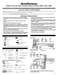
Wiring Quick Reference Guide<br />
Heavy Gauge<br />
Wires<br />
BLUE WHITE (+)<br />
PINK<br />
GREEN (+) output to ign/acc2 circuit<br />
PINK<br />
YELLOW<br />
MOMENTARY SWITCH PORT<br />
ANTENNA CABLE PORT<br />
SENSOR PORT<br />
YELLOW/RED (-) lock or (+) unlock output<br />
WHITE/RED (-) unlock or (+) lock output<br />
H1<br />
Fused light<br />
flash jumper Black (-)<br />
Heavy guage<br />
ground wire<br />
YELLOW (+/-) parking light output<br />
BROWN/WHITE (-) factory alarm disarm output<br />
VIOLET (-) negative hood pin shutdown output<br />
ORANGE (+) brake input<br />
WHITE/BLACK (-) 400mA status output<br />
RED/WHITE (-) remote start activation<br />
GREEN Tachometer input<br />
BLUE (-) 400mA horn/siren output<br />
RED/BLACK (-) wait-to-start input<br />
YELLOW/GREEN (+) ignition output<br />
GREEN/WHITE (-) 400mA trunk release output<br />
BROWN (-) 400mA RAP, Dome light, Starter kill output<br />
YELLOW/BROWN (-) 400mA Headlight output<br />
GRAY/BLACK (-) Door trigger input<br />
H2<br />
© 2006 Directed Electronics<br />
7
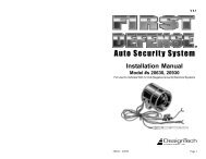
H1 Harness - 6 pin connector<br />
H1/1<br />
H1/2<br />
H1/3<br />
H1/4<br />
H1/5<br />
___<br />
___<br />
___<br />
___<br />
___<br />
YELLOW<br />
BROWN/WHITE<br />
VIOLET<br />
ORANGE<br />
WHITE/BLACK<br />
(+/-) parking light output<br />
(-) factory disarm output<br />
(-) hood pin shutdown input<br />
(+) brake switch shutdown input<br />
(-) 400mA status output<br />
H1/6<br />
___<br />
RED/WHITE<br />
(-) remote start activation input<br />
Pin # Color Note<br />
H1/1 Yellow Selectable positive or negative parking light output<br />
H1/2 Brown/White Use this wire if the vehicle is equipped with a<br />
factory alarm. Connect to disarm wire listed on your<br />
sheet.<br />
H1/3 Violet Connect this wire to supplied hood pin switch<br />
H1/4 Orange Connect this to wire in vehicle that shows 12 volts<br />
when brake is pressed<br />
H1/5 White/Black Provides a ground during remote start. This wire is<br />
normally connected to a bypass module if your<br />
vehicle needs one.<br />
H1/6 Red/White This wire will start the vehicle when it sees two<br />
negative pulses. Only used when incorporating into<br />
existing alarm or for testing purposes.<br />
8 © 2006 Directed Electronics
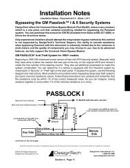
H2 Harness - 8 pin connector<br />
H2/1<br />
H2/2<br />
H2/3<br />
H2/4<br />
H2/5<br />
H2/6<br />
___<br />
___<br />
___<br />
___<br />
___<br />
___<br />
GREEN<br />
BLUE<br />
RED/BLACK<br />
YELLOW/GREEN<br />
GREEN/WHITE<br />
Tachometer input<br />
(-) 400mA horn/siren output<br />
(-) wait-to-start input<br />
(+) ignition output<br />
(-) 400mA trunk release output<br />
BROWN<br />
(-) 400mA RAP, Domelight, Starter Kill<br />
H2/7<br />
___<br />
YELLOW/BROWN<br />
(-) 400mA headlight output<br />
H2/8<br />
___<br />
GRAY/BLACK<br />
(-) door trigger input<br />
Pin # Color Note<br />
H2/1 Green Use this wire if the vehicle fails to start correctly in<br />
voltage mode<br />
H2/2 Blue Negative output to horn or siren circuit. If your horn is<br />
positive, use a relay.<br />
H2/3 Red/Black Used on diesel engines only. Connects to wait-to-start<br />
wire<br />
H2/4 Yellow/Green Ignition output. Connect this wire to the ignition input<br />
of an aftermarket alarm system.<br />
H2/5 Green/White Trunk release wire. Connect this wire to trunk release<br />
wire listed on your vehicle specific printout.<br />
H2/6 Brown Retained accessory shutdown or factory rearm output.<br />
Connect this wire to factory arm wire if equiped or to<br />
door trigger wire if your vehicle’s accessories stay on<br />
after remote start finishes cycle.<br />
H2/7 Yellow/Brown Headlight output. Connect this wire to headlight wire<br />
in car. If headlights are positive, a relay is required.<br />
H2/8 Gray/Black Door trigger input. This wire connects to the door trigger<br />
wire in your car to set off alarm when system is<br />
armed and door is opened.<br />
© 2006 Directed Electronics<br />
9
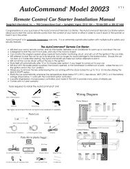
H3 harness - 3 pin connector<br />
H3/1<br />
H3/2<br />
H3/3<br />
___<br />
___<br />
___<br />
relay heavy gauge wires<br />
1<br />
2<br />
3<br />
4<br />
5<br />
___<br />
___<br />
___<br />
___<br />
___<br />
YELLOW/RED<br />
EMPTY<br />
WHITE/RED<br />
GREEN<br />
PINK<br />
BLUE<br />
WHITE<br />
PINK<br />
(-) lock/(+) unlock<br />
(-) unlock/(+) lock<br />
(+) Ign2 or Acc2 output<br />
(+) 12 volt input<br />
(+) ignition 1 output<br />
(+) accessory output<br />
(+) 12 volt input<br />
6<br />
___<br />
YELLOW<br />
(+) starter output<br />
BLACK<br />
(-) ground<br />
10 © 2006 Directed Electronics
Installation Overview<br />
Be sure to read this section thoroughly in its entirety before starting<br />
the installation. Pay special attention to all warnings to prevent<br />
personal injury or damage to your vehicle.<br />
Visit our 24-hour technical web site (www.autocommand.com) to<br />
get a vehicle-specific wiring guide prior to starting this installation.<br />
Have your crash code number handy when contacting tech support<br />
or visiting the web site. During the installation if you are unable<br />
to find answers to your questions on the web site, call 1-800-477-<br />
1382 for live technical assistance. Please note that live technical<br />
support is available Monday-Friday 6am-6pm PST, and Saturday-<br />
Sunday 7am-3:30pm PST.<br />
WARNING!<br />
➤<br />
➤<br />
➤<br />
Verify that the transmission is set to park and that<br />
the parking brake is set before beginning installation.<br />
On vehicles with air bags or supplemental restraint<br />
systems (SRS) you may notice a bright yellow tube<br />
with small wires in it marked SRS underneath the<br />
steering column near the key cylinder. DO NOT tamper<br />
or unplug these for any reason to prevent costly damages<br />
to your vehicle or personal injury. Tampering<br />
may cause unintended deployment of airbags.<br />
This system is intended for automatic, fuel-injected<br />
vehicles only. Installation in any other vehicle is contrary<br />
to its intended use.<br />
Step 1, Heavy Gauge Wire Connections<br />
© 2006 Directed Electronics<br />
11
Ground Wire<br />
The BLACK wire connects to the pin next to the light flash jumper<br />
fuse. First strip back a ¾-inch section of the insulation off the<br />
BLACK wire and crimp a ring terminal (not provided) to that wire.<br />
Locate a clean, paint-free metal surface in the drivers kick panel<br />
(do not ground on dash). Using a self-tapping screw, drill the<br />
screw with the ring terminal to the kick panel. Once screwed down,<br />
pull on the wire to ensure a good connection.<br />
SELF-TAPPING<br />
BOLT OR SCREW<br />
DIA-591<br />
NOTE: REMOVE ANY PAINT<br />
BELOW RING CONNECTOR<br />
RING<br />
TERMINAL<br />
GROUND<br />
WIRE<br />
Constant Power and Ignition wires<br />
Almost all your power and ignition wires can be found behind the<br />
key cylinder under the lower driver's side dash panel. Using the<br />
appropriate hand tools, remove the lower dash panel taking care<br />
not to break any parts. If the panel does not come off easily, check<br />
for any additional screws you may have missed.<br />
12 © 2006 Directed Electronics
Once the lower dash panel has been removed, locate the ignition<br />
harness at the back of the key cylinder. This is usually a group of<br />
heavy gauge wires (approximate 14ga.).<br />
Place the black lead of the LED tester to a clean metal surface in<br />
the kick panel area and secure it. Probe one of the thicker gauge<br />
wires. The ignition wire colors of your specific vehicle can be<br />
obtained at www.autocommand.com.<br />
note! More problems are attributed to poor ground<br />
connections than any other cause. Take extra care<br />
to ensure the ground is a clean metal-to-metal<br />
contact and secure.<br />
Testing for Constant Power Wires<br />
WARNING! Before making any connection to constant<br />
battery power make sure that the two 30 amp fuses<br />
are removed from the fuse holders on the two pink 12<br />
VOLT wires. Failure to do so may cause fire or shorting<br />
of sensitive electrical components.<br />
© 2006 Directed Electronics<br />
13
With the key in the off position, test the suspect wire. The<br />
constant power wire will read 12V on the multimeter. Once the<br />
constant power wire has been identified, solder the two heavy<br />
gauge 12 VOLT wires (PINK) from the control module to it and<br />
wrap the connection with electrical tape.<br />
note! If the vehicle has more than one constant<br />
power wire, utilize two of them. Connect one of the<br />
heavy gauge PINK wires to one of the constant<br />
power wires and the other heavy gauge PINK wire to<br />
the other constant power wire.<br />
Testing for Ignition Wires<br />
With the multimeter lead still connected in the kick panel, locate<br />
the suspected ignition wire. It will test differently than constant<br />
12 volts. Place the red lead of the multimeter on the suspected<br />
wire. With the key in the off position the multimeter will read 0.<br />
Turn the key to the on position and the multimeter will read 12<br />
volts. Now, watching your multimeter, turn the key to the crank<br />
position. If the 12 volts stays on, then you have found your ignition<br />
wire. If the wire tests correctly, solder the BLUE heavy gauge<br />
wire to it and wrap the connection with electrical tape.<br />
If the vehicle requires more than one ignition as per the web site<br />
information, follow the same test procedure and solder the GREEN<br />
heavy gauge wire to it then wrap the connection with electrical<br />
tape. If your vehicle has only one ignition wire, secure the GREEN<br />
wire and dress it out of the way.<br />
14 © 2006 Directed Electronics
If your vehicle requires more than two ignitions, an additional<br />
relay (not provided) is required. Refer to the diagram below.<br />
+12 VDC CONSTANT (FUSED 20A)<br />
2 nd IGNITION RELAY<br />
(NOT PROVIDED)<br />
TO 2 nd IGNITION<br />
87<br />
86 87A 85<br />
30<br />
GROUND<br />
TO 2 nd IGNITION<br />
+12 VDC CONSTANT (FUSED 20A)<br />
3 rd IGNITION RELAY<br />
(NOT PROVIDED)<br />
GREEN (+) OUTPUT<br />
TO 2 nd IGNITION<br />
87<br />
86 87A 85<br />
30<br />
GROUND<br />
TO 3 rd IGNITION<br />
© 2006 Directed Electronics<br />
15
Accessory and Starter wires<br />
The starter and accessory wires will be located in the same harness<br />
as the ignition and constant power.<br />
To find the accessory wire leave the multimeter’s black lead<br />
connected to ground. Take the red lead and probe the wire<br />
suspected to be the accessory wire. With the key off, your multimeter<br />
should read 0 volts. Turn the key to the on position the<br />
multimeter should read 12 volts. Now turn the key to the crank<br />
position. If you have the correct accessory wire the multimeter<br />
will read 0 volts while the starter is cranking and 12 volts once<br />
the key returns to the on position. If the wire tests correctly, strip<br />
some insulation off and solder the WHITE heavy gauge wire and<br />
wrap it with electrical tape.<br />
If your vehicle requires more than one accessory then the GREEN<br />
ign2 wire can be programmed to function as an accessory output.<br />
16 © 2006 Directed Electronics
If the GREEN wire is being used for ign2 an additional relay (not<br />
provided) is required for a 2nd accessory. Refer to the diagram<br />
below.<br />
+12 VDC CONSTANT (FUSED 20A)<br />
ACCESSORY RELAY<br />
(NOT PROVIDED)<br />
TO ACCESSORY<br />
87<br />
86 87A 85<br />
30<br />
GROUND<br />
TO ACCESSORY<br />
+12 VDC CONSTANT (FUSED 20A)<br />
2 nd ACCESSORY RELAY<br />
(NOT PROVIDED)<br />
WHITE (+) 30A OUTPUT TO<br />
ACCESSORY CIRCUIT<br />
87<br />
86 87A 85<br />
30<br />
GROUND<br />
TO 2 nd ACCESSORY<br />
Now that the accessories have been located, find the suspected<br />
starter wire according to the web information. Leave the black<br />
lead of your tester on ground and place the red lead of your multimeter<br />
on this wire. The multimeter should read 0 volts in all key<br />
positions except the crank position. In the crank position your<br />
multimeter should read 12 volts, and will go to 0 volts when the<br />
starter disengages.<br />
© 2006 Directed Electronics<br />
17
Many Nissan and late-model Chrysler vehicles have two starter<br />
wires. A relay and/or resistor (not provided) is required to hook up<br />
the additional starter wire. Refer to the diagram below.<br />
+12 VDC CONSTANT (FUSED 20A)<br />
STARTER RELAY<br />
(NOT PROVIDED)<br />
TO STARTER<br />
87<br />
86 87A 85<br />
30<br />
GROUND<br />
TO STARTER<br />
+12 VDC CONSTANT (FUSED 20A)<br />
2 nd STARTER RELAY<br />
(NOT PROVIDED)<br />
YELLOW (+) OUTPUT<br />
TO STARTER<br />
87<br />
86 87A 85<br />
30<br />
GROUND<br />
TO 2 nd STARTER<br />
note! Always check the Web site information<br />
on your vehicle for warnings regarding the<br />
starter wire and check engine lights. Some<br />
vehicles will trip a check engine light if the<br />
starter wire is cut.<br />
Once you locate the starter wire, cut the wire in half (check the<br />
web information before cutting) and try to start the vehicle. If<br />
the vehicle does not start, the correct wire has been identified.<br />
Reconnect both ends of the starter wire while soldering the thick<br />
YELLOW (6) wire of the heavy guage wires to it and wrap the<br />
connection with electrical tape.<br />
18 © 2006 Directed Electronics
Step 2, H1, Main Harness Connections<br />
Factory Alarm Disarm<br />
Since many newer vehicles come equipped with a factory alarm it<br />
is necessary to disarm it when unlocking the doors or during<br />
remote start. Do not mistake a factory alarm with an immobilizer<br />
system. They each require different disarm operations.<br />
Locate the factory alarm disarm wire using the web site information.<br />
Once the suspect wire is located, place the multi-meter's red<br />
lead to a (+)12 volt constant source and secure it. Put the multimeter<br />
in the DC position then probe the suspect wire with the<br />
black lead of your meter. While probing the wire, place the key in<br />
the driver's door cylinder. Turn it to the unlock position and hold<br />
it when testing for the disarm wire. The multimeter should read<br />
12V and will go back to 0V when the key is released.<br />
When the correct wire has been found, solder the BROWN/WHITE<br />
wire of the 6-pin harness to the wire that you determined to be<br />
the factory alarm disarm wire. After this wire has been connected<br />
wrap the connection with electrical tape.<br />
note! On some vehicles the Factory Alarm Disarm<br />
wire is connected to a Body Control Module or a Door<br />
Module. If you find this configuration, please call<br />
Technical Support at 1-800-477-1382.<br />
note! Some vehicles use a + trigger factory alarm<br />
system. Use the website to determine if your vehicle<br />
has a + trigger. If your vehicle has such a system call<br />
1-800-477-1382 for live technical assistance as special<br />
wiring and an additional relay is required.<br />
© 2006 Directed Electronics<br />
19
Parking light flash<br />
There are several different types of parking light circuits. The<br />
following description is for a standard positive-triggered parkinglight<br />
circuit, only. If the web vehicle information suggests a (-)<br />
parking light circuit, the fuse jumper (on the side of the module)<br />
must be moved to the opposite position.<br />
The default position for this jumper is for a positive parking light<br />
circuit.<br />
Using the web information on the vehicle, locate the suspected<br />
wire. Connect the black multimeter lead to ground in the kick<br />
panel. Probe the suspected wire with the red lead of your meter.<br />
With the switch in the off position the multimeter should read 0<br />
volts. While watching the multimeter, turn your headlight switch<br />
to the parking light position. The multimeter should read 12 volts.<br />
While testing the suspected wire, run the dash dimmer light<br />
control up and down-the voltage should NOT vary. If the voltage<br />
does vary then this is the wrong wire. Continue probing to find the<br />
correct wire.<br />
Once you have identified the correct wire, solder the small YELLOW<br />
wire of the 6-pin harness to it and wrap the connection with electrical<br />
tape.<br />
important! Remember this description is for a (+)<br />
parking light circuit. A (-) circuit will test differently.<br />
Also, if the web information requires using resistors<br />
for parking lights, contact Technical Support.<br />
20 © 2006 Directed Electronics
Safety Shutdown Wires<br />
With all ignition wires properly connected, find the appropriate<br />
safety shutdown wires. These are the brake wire and hood pin<br />
wires.<br />
WARNING! These wires are meant to protect the<br />
vehicle and anyone near the vehicle. They MUST<br />
be connected to prevent damage to the vehicle<br />
and possible bodily injury.<br />
First locate the factory brake wire using your multimeter. Find the<br />
switch at the top of the metal arm coming off the brake pedal. Use<br />
your vehicle specific wiring information to determine the color of<br />
this wire. With the black lead of your multimeter still in the kick<br />
panel, probe the suspected wire with the red lead of your multimeter.<br />
With the brake pedal at rest the multimeter should read 0<br />
volts. While watching the multimeter, depress the brake pedal.<br />
The multimeter should read 12 volts. Once you have located the<br />
correct brake wire, solder the small ORANGE wire in the 6-pin<br />
harness to it and wrap the connection with electrical tape.<br />
WARNING! Do not use the vehicle until you<br />
confirm the operation of the brake shutdown.<br />
Installing the hood pin switch requires drilling a hole in a metal<br />
lip under the hood. Choose a location that will allow the pin<br />
switch to be completely depressed when the hood is closed. The<br />
pin switch has a spade connector on the bottom for the wire<br />
connection.<br />
Crimp your spade connector to the hood pin wire and run the wire<br />
into the vehicle's passenger compartment through a factory rubber<br />
grommet (at the same time you might want to run Tachometer<br />
Input wire and Horn output wire from Optional Harness through<br />
the fire wall as you may need to connect them using the following<br />
steps).<br />
© 2006 Directed Electronics<br />
21
Using a sharp, pointed object poke a hole into the grommet<br />
(being careful not to damage any existing wires in the grommet)<br />
and attach the wire to the object with electrical tape. Pull the<br />
wire through the grommet taking extra care to keep the wire away<br />
from any moving parts or anything that will generate extreme<br />
heat.<br />
An alternative to this method would be to find a spot on the firewall<br />
with sufficient clearance on both sides and drill an access<br />
hole through the firewall. Take note of what is directly on the<br />
other side of where you are drilling as to not puncture brake cylinders,<br />
computers, etc. Once the wire is run into the vehicle and<br />
secured from any moving parts, solder the wire to the VIOLET wire<br />
of the 6-pin harness and wrap the connection with electrical tape.<br />
WARNING! This wire MUST be connected. Do not<br />
use the vehicle until you confirm the operation<br />
of the hood pin shutdown. Improper operation<br />
could result injury or death.<br />
22 © 2006 Directed Electronics
Step 3, H3 Door Lock Connections<br />
There are 8 different types of door lock systems (Type A - H).<br />
Refer to the vehicle-specific wiring instructions on the web and<br />
the chart below to help determine which door lock system your<br />
vehicle uses. On some late model GM vehicles a door lock data<br />
interface module may be required.<br />
Type A: Three-wire (+) pulse controlling factory lock relays.<br />
Type B: Three-wire (-) pulse controlling factory lock relays.<br />
note! From the factory, your system is set up for Type<br />
B (-) door locks. To change your door lock outputs to<br />
Type A (+), simply use the wires in the oposite configuration.<br />
You will now have (+) door locks.<br />
Type C: Direct-wired reversing-polarity switches. The switches are<br />
wired directly to the motors. This type of system has no factory<br />
relays. Relays (not included) will be required for this type of door<br />
lock system.<br />
Type D: Adding one or more aftermarket actuators. These include<br />
slave systems without an actuator in the driver's door, but with<br />
factory actuators in all the other doors.<br />
Type E: Electrically-activated vacuum systems.<br />
Type F: One-wire system - cut to lock, ground to unlock.<br />
This is a vary rare system found only mainly in early 90's imports<br />
Type G: Positive (+) multiplex. One wire controls lock and unlock<br />
using resistor(s).<br />
Type H: Negative (-) multiplex. Same as type G system, but uses<br />
(-) pulse instead.<br />
© 2006 Directed Electronics<br />
23
All other door lock systems will require additional relays and/or<br />
resistors. A Directed Electronics 451M Doorlock module can be<br />
used for these other applications. The 451M also includes<br />
diagrams and resistors required for most applications.<br />
24 © 2006 Directed Electronics
Step 4, H2 Harness<br />
Engine Monitoring Explained<br />
During remote start the system will need to know if the engine is<br />
running. The module does this by monitoring the voltage of the<br />
vehicle's electrical system (or the tachometer-see next section).<br />
Voltage Monitoring<br />
note! If the system has been programmed for<br />
Tachometer monitoring previously, it must be<br />
reprogrammed to Voltage monitoring.<br />
Vehicle electrical systems usually rest at about 12.6 volts when<br />
the engine is not running. This system is programmed to detect<br />
the rise in battery voltage that occurs when the charging circuit<br />
activates after starting, and keep the engine running if the rise is<br />
adequate. It will make up to three start attempts before discontinuing<br />
due to an inadequate voltage rise.<br />
Some vehicles have alternators that do not activate immediately<br />
or do not increase voltage sufficiently after starting, this system<br />
will compensate by delaying the time before reading the battery<br />
voltage on the second and third start attempts. This delay will<br />
allow most alternators to activate so the remote start will<br />
continue to run.<br />
The voltage read times are:<br />
© 2006 Directed Electronics<br />
First attempt: 10 seconds<br />
Second attempt: 20 seconds<br />
Third attempt: 50 seconds<br />
After the third start attempt, if the voltage increase is still not<br />
adequate to keep the engine running, the Tachometer input<br />
option should be used to monitor the engine.<br />
25
Tachometer Wire<br />
WARNING! In the following procedure DO NOT use<br />
a test light. Use of this type of tester can cause<br />
grounding of sensitive electrical components causing<br />
damage, including damage to the power train<br />
control module. A digital multi-meter is required to<br />
test for this wire.<br />
Do not wear loose clothing that could get entangled<br />
in rotating engine components. Ensure that your<br />
hands and arms are well clear of these rotating<br />
components when working in the engine compartment.<br />
Lastly, ensure that all wires and tools are<br />
clear of falling into or entanglement with these<br />
rotating components.<br />
Identify the suspected tach wire according to the web information.<br />
Next, place the black lead of a MULTI-METER on the negative<br />
battery post and secure it. Put the multi-meter in the AC position<br />
and connect the probe to the suspect wire with the red lead<br />
of the multi-meter. Then start the vehicle with the key. With the<br />
engine at idle the multi-meter should read between .50 volts to 6<br />
volts, and should fluctuate when you rev the engine.<br />
Have a second person press the gas pedal to increase the RPMs<br />
and watch the meter display. When the RPMs increase the voltage<br />
should rise slightly (not all tachometer outputs will rise when<br />
engine RPM increases). Once the correct tachometer wire has been<br />
identified, turn the vehicle off.<br />
Run the GREEN wire from the 8-pin harness through the firewall<br />
into the engine compartment along side the hood pin wire. Use<br />
the same procedure as with the hood pin wire and pull the wire<br />
through the grommet taking extra care to keep it away from any<br />
moving parts or anything that will generate extreme heat. Once<br />
the wire is run into the engine compartment, strip a small portion<br />
26 © 2006 Directed Electronics
of insulation off the tachometer wire in the vehicle and solder the<br />
green tachometer input wire to it. Then wrap the connection with<br />
electrical tape.<br />
note! If using a tach signal, the tach signal MUST<br />
be learned before using the remote starter.<br />
LEARNING YOUR TACH SIGNAL<br />
If using a tach wire, you must learn the tach signal after<br />
completing the installation.<br />
To learn tach signal:<br />
1. Start car with key<br />
2. Wait about 5 seconds for the engine to idle down<br />
3. Press and hold the Momentary switch (about 10<br />
seconds)<br />
4. Tach learned: After a few seconds the LED will flash 2<br />
times and turn on. Continue to hold the switch for 2 - 3<br />
seconds and release.<br />
5. Tach not learned: The LED will not turn on and will flash<br />
3 times when the momentary switch is released. Check<br />
the connections and try again.<br />
© 2006 Directed Electronics<br />
27
Following is a brief description of the remainder of the wires in<br />
the H2 harness. For specific details on connecting these outputs<br />
contact Technical Support at 1-800-477-1382.<br />
Horn/siren wire<br />
The Blue wire provides an output for activating the vehicle horn<br />
circuit or an external siren. The output is programmable in Feature<br />
Menu 1/9 for the desired use.<br />
important! This is a low current output and that<br />
requires an external relay when connected to circuits<br />
that draw more than 400mA in current.<br />
Wait-to-start wire<br />
The Red/Black wire is for use with diesel engines that require a<br />
short delay for the glow plugs to warm up before cranking the<br />
engine. Connect this wire to the wire in the vehicle that sends the<br />
signal to turn on the WAIT-TO-START bulb in the dashboard. In<br />
most diesels the wire is negative (ground turns on the bulb) and<br />
the Red/Black wire can be directly connected. If the vehicle uses<br />
a positive wire (12V to turn on the bulb) a relay must be used to<br />
change the polarity.<br />
Ignition Output wire<br />
The Yellow/Green wire should be the ONLY the ignition input to an<br />
existing aftermarket alarm system. This wire will prevent the host<br />
system from sensing that the ignition is on during remote start<br />
operation.<br />
Trunk Release wire<br />
The Green/White wire can be used to activate a vehicle trunk<br />
release solenoid or to operate optional modules that require a<br />
negative input. Whenever the button is pressed for a few<br />
seconds the system will disarm/unlock and then activate this<br />
28 © 2006 Directed Electronics
output. The output will then remain on until the transmitter<br />
button is released.<br />
important! this is a low current output and that<br />
requires an external relay when connected to circuits<br />
that draw more than 400mA in current.<br />
Retained Accessory, Dome Light or Starter Kill wire<br />
The Brown wire has three optional uses depending on the vehicle<br />
application and user preference. The three available operations are<br />
programmable in Feature Menu 2/11<br />
➤<br />
➤<br />
➤<br />
RAP or Retained Accessory Power: This option is<br />
designed to turn off accessories that remain on after the<br />
ignition is turned off. It will pulse 10 seconds after the<br />
remote start status output ceases. It will make the vehicle<br />
body control module think the door has opened, thus<br />
turning the accessories off.<br />
Dome Light Supervision: This option will turn on the<br />
dome light for 25 second each time the vehicle is<br />
unlocked. It will cease if on when the doors are locked<br />
or the ignition in turned on.<br />
Start Kill/Anti-grind: This option activates when the<br />
doors are locked to allow for starter kill for the alarm<br />
system and also works as an anti-grind when the remote<br />
start is active.<br />
important! this is a low current output and that<br />
requires an external relay when connected to circuits<br />
that draw more than 400mA in current.<br />
© 2006 Directed Electronics<br />
29
Headlight Control wire<br />
The Yellow/Brown wire provides an output for activating the<br />
vehicle headlight circuit. It is controlled by both the ignition<br />
switch and the transmitter. It is programmable in Feature Menu<br />
1/10 for the type of ignition controlled activation.<br />
important! this is a low current output and that<br />
requires an external relay when connected to circuits<br />
that draw more than 400mA in current.<br />
Door Trigger wire<br />
The Gray/Black wire will trigger the alarm and is designed to be<br />
connected to the door switch that turns on the dome light when<br />
the door is opened. It is a negative input circuit only. If your<br />
vehicle uses a positive door switch circuit, call for assistance in<br />
making the connection.<br />
30 © 2006 Directed Electronics
Step 5, Mounting the Receiver/Antenna<br />
Receiver/antenna position should be discussed with the vehicle<br />
owner prior to installation, since the antenna may be visible to<br />
the vehicle’s operator.<br />
The best location for the receiver/antenna is centered high on<br />
either the front or rear windshield. For optimal range, the antenna<br />
should be mounted vertically. It can be mounted horizontally<br />
in relation to the windshield or under the dashboard away from<br />
metal, but range will be diminished. Metallic window tint can also<br />
affect range, so this should be a consideration when determining<br />
the mounting location.<br />
After determining the best mounting location, follow these steps:<br />
1. Clean the mounting area with a quality glass cleaner or<br />
alcohol to remove any dirt or residue.<br />
2. Plug the receiver/antenna cable into the<br />
receiver/antenna.<br />
3. Mount the receiver/antenna using the supplied doublesided<br />
tape.<br />
4. Route the receiver/antenna cable to the control module<br />
and plug it into the four-pin antenna connector.<br />
important! To achieve the best possible range,<br />
DO NOT leave the antenna cable bundled under<br />
the dash. Always extend the cable full length during<br />
installation, regardless of the antenna mounting<br />
location.<br />
© 2006 Directed Electronics<br />
31
32 © 2006 Directed Electronics
Step 6, Immobilizer Bypass Modules<br />
Most newer vehicles have a factory engine immobilizer system<br />
designed to prevent any unauthorized use of the vehicle. These<br />
immobilizers will cut off power to the starter and the fuel supply<br />
preventing a thief from starting the vehicle.<br />
There are several types of immobilizers, with the most common<br />
being the resistance-based passlock/passlock 2 systems found on<br />
most newer GM vehicles. This system can be bypassed using the<br />
20402, 29402 or 556L immobilizer bypass modules available at<br />
your local authorized retailer or at www.directedstore.com. The<br />
majority of transponder-based immobilizer systems can be<br />
bypassed using the 20402, 29402 or 556U immobilizer bypass<br />
module available at your local authorized retailer.<br />
The WHITE/BLACK wire of the 6-pin harness supplies a 400mA (-)<br />
output as soon as the control module begins the remote start<br />
process. This wire can be used to activate an immobilizer bypass<br />
unit.<br />
note! Any vehicle equipped with a factory immobilizer<br />
must use an immobilizer bypass module to<br />
remote start. If not used, the vehicle ignition or<br />
fuel supply circuits could lock up and require a<br />
costly trip to the dealer to reset the computer system.<br />
To determine which bypass module your vehicle requires, use the<br />
website Interface Module Look-Up tool at the following website:<br />
www.autocommand.com.<br />
© 2006 Directed Electronics<br />
33
Step 7, Programming<br />
Programming transmitters<br />
Your system can learn up to 4 transmitters. The following procedure<br />
will show you how to add additional transmitters or replace<br />
old ones. Each transmitters can be programmed one button at a<br />
time or you can use an auto learn procedure that learns the<br />
intended factory configuration. Learning one button at a time is<br />
generally only used when using one transmitters to control two<br />
different cars. Being able to program functions to different channels<br />
on each transmitters prevents multiple cars from responding<br />
simultaneously.<br />
1. Turn the ignition ON<br />
2. Press/release the momentary switch the same number of<br />
times as the desired transmitter learn Step number, and<br />
then Press/HOLD.<br />
3. After Holding the momentary switch for 2 seconds the<br />
LED will begin to flash to indicate of the accessed transmitter<br />
learn Step.<br />
4. Press the transmitter button that you want to control<br />
the function assigned to that transmitter learns Step;<br />
the Horn/Siren will emit a long chirp.<br />
note! For transmitter learn Step #1, you must press<br />
the “*” button on the transmitter, this will automatically<br />
program the transmitter buttons to the<br />
default function configuration. See the transmitter<br />
button auto learn chart for the assignment<br />
functions.<br />
34 © 2006 Directed Electronics
You can learn more than one transmitter function at a time by<br />
advancing to another transmitter learn Step.<br />
To do this, first release the momentary SW and then press/release<br />
it the same number of times as the difference between the current<br />
transmitter learn Step and the desired transmitter learn Step, and<br />
then press/HOLD it.<br />
example! To advance from transmitter learn Step 2<br />
to transmitter learn Step 8, release the momentary<br />
SW and then press/release it 6 times and HOLD it<br />
on the 7th press.<br />
After Holding the Valet Sw for 2 seconds the LED will flash 8 times<br />
and repeat. You can now learn a transmitter button to step 8.<br />
There are several ways to exit transmitter Learning, by TimeOut,<br />
Ignition or momentary SW Presses.<br />
1. TimeOut: If more than 15 seconds elapse between<br />
momentary SW presses or transmitter signals.<br />
2. Ignition: If the Ignition is turned off at any time during<br />
transmitter Learning.<br />
3. Momentary SW presses: if you press/release the momentary<br />
SW more times than transmitter Learning steps in<br />
the menu.<br />
The Horn output will pulse 5 times rapidly and the Led will turn<br />
off to indicate exiting feature programming.<br />
© 2006 Directed Electronics<br />
35
Transmitter Button Programming Chart<br />
Step Function Button Assignment<br />
1 Auto-Program ALL buttons to the factory default functions<br />
2 <strong>Remote</strong> Start <strong>Remote</strong> Start/Stop function<br />
3 Trunk Pop Carfinder & Trunk Pop functions<br />
4 Headlight/Panic/Silent Headlight, Silent mode & Panic functions<br />
5 Arm & Lock Arm & Lock function<br />
6 Disarm & Unlock Disarm & Unlock functions<br />
7 Daily Start Daily Start function<br />
8 Vacation Mode Vacation Start function<br />
9 Delete ALL TXs Removes ALL transmitters from memory<br />
Transmitter Button Auto-Learn<br />
<strong>Remote</strong> Start/Stop<br />
CarFinder & Disarm/Trunk Pop<br />
Head Light control, Panic & Silent mode<br />
Arm & Lock<br />
Disarm & Unlock<br />
&<br />
&<br />
Vacation Mode<br />
Daily Start<br />
36 © 2006 Directed Electronics
Programming System Settings<br />
Many of the features and operations of this system can be<br />
changed to suit most of today's vehicle electrical systems. The<br />
programming routine and feature menus that follow will allow<br />
making the changes required for most vehicle installations.<br />
System programming routine:<br />
Accessing a Menu:<br />
1. Turn the ignition ON and then OFF in less than 5 seconds<br />
2. Within 3 seconds Press/Hold the Momentary Switch<br />
3. After 2 seconds the LED will flash and the Horn/Siren<br />
will pulse to indicate the available menus. It will toggle<br />
through the outputs until a menu is chosen.<br />
a. Menu 1: 1 LED flash and Horn/Siren pulse<br />
b. Menu 2: 2 LED flashes and Horn/Siren pulses<br />
4. Release the Momentary Switch after the appropriate<br />
output to access that Menu. The LED and Horn/Siren<br />
outputs will cease.<br />
Accessing a Feature Location:<br />
1. Press and release (do not hold) the Momentary Switch<br />
the same number of times as the feature location to be<br />
accessed. See the Feature Chart for locations.<br />
2. After 2 seconds the LED will flash (the number of flashes<br />
will match with the feature location) to confirm the<br />
feature location. It will flash/pause and repeat until the<br />
feature is changed or programming is exited.<br />
3. Press a button on the transmitter to change the feature<br />
© 2006 Directed Electronics<br />
37
option<br />
a. Option 1: Press the transmitter button assigned to<br />
the <strong>Remote</strong> Start function (usually the button) to<br />
set factory default Option 1.<br />
The LED will turn ON and the Horn/Siren will pulse once.<br />
b. Option 2-4: Press the transmitter button assigned to<br />
the CarFinder function (usually the button) to set<br />
Options 2-4 if available.<br />
The LED will flash and the Horn/Siren will pulse 2-4<br />
times to indicate the option and the LED continue to<br />
flash to indicate the option.<br />
Access a different Menu:<br />
To change features in a different menu or return to the beginning<br />
of the accessed menu return to Step 2 under Accessing a Menu at<br />
any time.<br />
Advance to different feature location:<br />
To advance to a new locations within the same menu<br />
press/release the Momentary Switch the same number of times as<br />
the difference between the feature locations.<br />
example! to advance from feature location 2 to feature<br />
location 8 press/release (do not hold) the Momentary<br />
switch 6 times, after 2 seconds the LED will flash 8<br />
times to indicate the newly accessed feature location.<br />
38 © 2006 Directed Electronics
Exiting Feature programming:<br />
The following will cause the system to exit programming and is<br />
indicated by 5 short chirps of the Horn/Siren output.<br />
Feature Menus<br />
a. More than 15 seconds lapses between inputs by<br />
Momentary switch or transmitter button<br />
b. The ignition is turned on<br />
Feature Menu 1 Chart<br />
Feature<br />
Location<br />
Feature Name Option 1<br />
(Default)<br />
Option 2 Option 3 Option 4<br />
1 Engine Monitoring No Tach Tach NA NA<br />
2 Run Time 15 min 30 min NA NA<br />
3 Crank time Normal ExtraCrank Super crank Mega crank<br />
4 Ign2 Output Ign 2 ACC 2 NA NA<br />
5 Wait-to-start Diesel Input Diesel Timer NA NA<br />
wire<br />
6 Activation Input 2 pulse 1 pulse NA NA<br />
7 Vacation Temp 0 degrees F -10 degrees F -20 degrees F NA<br />
8 Alarm Disarm 1 second 450 ms NA NA<br />
9 Horn Output Horn/Pulsing Siren/Constant NA NA<br />
10 Headlights Daytime Light your NA<br />
NA<br />
way<br />
11 Start Chirp On Off NA NA<br />
12 NA NA NA NA NA<br />
13 Reset All Options Press ANY TRANSMITTER button to reset all<br />
features<br />
© 2006 Directed Electronics<br />
39
Feature Menu 1 Descriptions<br />
1. Engine Monitoring: Defines how the engine is monitored while<br />
the <strong>Remote</strong> Start is active.<br />
1. No Tach: The battery voltage will be used to monitor the<br />
engine while <strong>Remote</strong> Start is active.<br />
2. Tachometer: The tachometer will be used to monitor<br />
engine speed while <strong>Remote</strong> Start is active.<br />
2. Run Time<br />
1. 15 minutes: The <strong>Remote</strong> Starter will shut down after it<br />
has been active for 15 minutes.<br />
2. 30 minutes: The <strong>Remote</strong> Starter will shut down after it<br />
has been active for 30 minutes.<br />
3. Crank Time: Crank Time will be in effect only when Engine<br />
Monitoring is "No Tach" and affects the duration of the "Yellow"<br />
Starter Output wire.<br />
1. Normal Crank: The Starter output will be 700mS.<br />
2. Extra Crank: The Starter output will be 1 second.<br />
3. Super Crank: The Starter output will be 1.4 seconds.<br />
4. Mega Crank: The Starter output will be 2.1 seconds.<br />
4. Ignition 2 Output: This controls the output type of the high<br />
current "Green" ignition 2 output wire.<br />
1. Ignition 2: Output will match the Blue Ignition 1<br />
input/output wire operation during remote start.<br />
2. Accessory 2: Output will match the White Accessory 1<br />
output wires operation.<br />
40 © 2006 Directed Electronics
5. Wait-To-Start: This chooses the method of Starter output delay<br />
for Diesel engines.<br />
1. Diesel Input wire: An input on the "Red/Blk" wire will<br />
delay the Start output until the input ceases.<br />
2. Diesel Timer: The Starter output will be delayed until the<br />
timer expires. The "Red/Blk" wire will be ignored.<br />
6. Activation Input: Selects the number of inputs from the transmitter<br />
or the "Red/Wht" activation input wire to activate the<br />
<strong>Remote</strong> Starter.<br />
1. 2 Pulses: Two input pulse will Start and Stop the <strong>Remote</strong><br />
Starter<br />
2. 1 Pulse: One input pulse will Start and Stop the <strong>Remote</strong><br />
Starter<br />
7. Vacation Temp: Selects the temperature threshold that will<br />
activate the <strong>Remote</strong> Starter when Vacation Mode has been activated.<br />
1. 0 Degrees F<br />
2. -10 Degrees F<br />
3. -20 Degrees F<br />
8. Alarm Disarm: Selects the output duration of the "Brown/Wht"<br />
Factory Alarm Disarm wire.<br />
1. 1 second: The output will be 1 second in duration<br />
2. 450mS: The output will be 450mS in duration<br />
9. Horn Output: Selects the type of output on the "Blue" Horn<br />
output wire when the alarm is fully triggered but does not affect<br />
the arm/disarm/remote start/programming chirp outputs<br />
© 2006 Directed Electronics<br />
41
1. Horn: The output will be pulsed during full trigger events<br />
2. Siren: The output will be constant during full trigger<br />
events.<br />
10. Headlights: Selects the operation of the "Yellow/Brn" headlight<br />
output wire when an ignition input is sensed.<br />
1. Daytime Running: The output will activate 10 seconds<br />
after an ignition input is sensed and cease output 1<br />
second after the ignition input ceases.<br />
2. LightYourWay: The output will activate for 25 seconds<br />
immediately after the ignition input ceases.<br />
11. Start Chirps: Selects if the "Blue" Horn/Siren output wire will<br />
pulse when activating <strong>Remote</strong> Starter.<br />
1. On: The Horn output will pulse 1 time at the beginning<br />
of <strong>Remote</strong> Start<br />
2. Off: The Horn output WILL NOT pulse at the beginning<br />
of <strong>Remote</strong> Start<br />
12. NA: A feature is Not Available for this Location<br />
13. Reset All Options: Pressing a transmitter button when this<br />
Feature Location is accessed will "Reset All Options" in both<br />
menus to their default setting.<br />
42 © 2006 Directed Electronics
Feature Menu 2 Chart<br />
Feature<br />
Location<br />
Feature Name Option 1<br />
(Default)<br />
Option 2 Option 3<br />
1 Arming Type Active Passive NA<br />
2 Locking Type Active Passive NA<br />
3 Ignition Locking OFF Lock w/Ign On NA<br />
/ Brake<br />
4 Ignition Unlocking OFF Unlock w/Ign NA<br />
OFF<br />
5 Lock Pulses 1 2 NA<br />
6 Unlock Pulses 1 2 NA<br />
7 Lock Duration Short 0.8<br />
seconds<br />
Long 3.5<br />
seconds<br />
8 Alarm Mode ON OFF NA<br />
NA<br />
9 Auto Rearming OFF ON NA<br />
10 Alarm Chirps ON OFF NA<br />
11 ACC<br />
Pulses/Domelight/St<br />
arter kill<br />
Accessory<br />
Pulse (RAP)<br />
Domelight<br />
Starter<br />
Kill/Antigrind<br />
Output<br />
Feature Menu 2 Descriptions<br />
1. Arming Type: Selects if the alarm will arm by one or both available<br />
methods.<br />
1. Active: The alarm will arm via transmitter only<br />
2. Passive: The alarm will arm via transmitter and Passive<br />
Arming criteria.<br />
2. Locking Type: Selects the type of arming operations the door<br />
locks will activate with.<br />
1. Active: The doors will lock when armed via transmitter<br />
and Auto Re-arming.<br />
© 2006 Directed Electronics<br />
43
2. Passive: The doors will lock when armed via transmitter,<br />
Passive Arming and Auto Re-arming.<br />
3. Ignition Locking: Selects if the door locks will activate after an<br />
ignition input is sensed.<br />
1. Off: The Door Lock output will not activate due to an<br />
ignition input sense.<br />
2. On: The Door Lock output will activate when the brake<br />
input and an ignition input is sensed.<br />
4. Ignition Unlocking: Selects if the door locks will activate after<br />
the ignition input ceases.<br />
1. Off: The Door Unlock output will not activate when the<br />
ignition input ceases.<br />
2. On: The Door Unlock output will activate 100mS after<br />
the ignition is turned off.<br />
5. Lock Pulses: Selects the number of pulses when locking the<br />
doors.<br />
1. 1 pulse: The Door Lock output will be one pulse for the<br />
programmed duration.<br />
2. 2 pulses: The Door Lock output will be 2 pulses for the<br />
programmed duration.<br />
6. Unlock Pulses: Selects the number of pulses when Unlocking the<br />
doors.<br />
1. 1 pulse: The Door Unlock output will be a single pulse<br />
for the programmed duration.<br />
2. 2 pulses: The Door Unlock output will be a double pulse<br />
for the programmed duration.<br />
44 © 2006 Directed Electronics
7. Lock Duration: Selects the duration of the pulses when Locking<br />
and Unlocking the doors.<br />
1. Short pulse: The Door Lock & Unlock outputs will be<br />
800mS in duration.<br />
2. Long pulse: The Door Lock & Unlock outputs will be a<br />
3.5 seconds in duration.<br />
8. Alarm Mode: Selects if the alarm functions are active or<br />
bypassed.<br />
1. On: Alarm functions are operational as described<br />
2. Off: Alarm functions are NOT operational, but convenience<br />
features and <strong>Remote</strong> Starter still operate<br />
normally.<br />
9. Auto Re-arming: Selects if the units will automatically Rearm/lock<br />
itself if alarm inputs 1 or 6 are not activated after transmitter<br />
disarm/unlock.<br />
1. Off: The unit WILL NOT automatically Arm/Lock the<br />
doors after transmitter Disarm/Unlock.<br />
2. On: The unit will automatically Arm/Lock the doors 120<br />
seconds after transmitter Disarm/Unlock if Alarm Inputs<br />
1 or 6 remain idle.<br />
10. Alarm Chirps: Selects if the "Blue" Horn output wire will pulse<br />
when Arm/Lock and Disarm/Unlock are activated.<br />
1. On: The Horn output will pulse 1 time for Arm/Lock and<br />
2 times for Disarm/Unlock.<br />
2. Off: The Horn output WILL NOT pulse for Arm/Lock or<br />
Disarm/Unlock.<br />
© 2006 Directed Electronics<br />
45
11. Acc pulse/DomeLight/ Starter Kill-Anti-grind: This controls<br />
the output of the "Brown" output wire.<br />
1. Accessory Pulse: This output will pulse 10sec after the<br />
<strong>Remote</strong> Starter shuts down, except when the ignition<br />
input is active.<br />
2. Dome Light: This output will turn on for 25sec after the<br />
Unlock output is completed, and cease if the Ignition is<br />
turned on.<br />
3. Starter Kill: This output will activate when the Alarm<br />
system is Armed for disabling the vehicle starter circuit<br />
and when remote started for Anti-grind.<br />
46 © 2006 Directed Electronics
System Diagnostics<br />
Alarm diagnostics<br />
When arming or disarming the alarm, this system will alert you of<br />
alarm triggers or active inputs by changing the Horn/Siren and<br />
light flash output. It will then indicate the active input by<br />
flashing the LED.<br />
Arming diagnostics:<br />
When arming, if an alarm input is active (door or hood open) the<br />
Horn/Siren output and Parking Lights will pulse three times<br />
instead of one as an alert.<br />
The LED will then flash/pause and then repeat 5 times to indicate<br />
the active input (See alarm input chart)<br />
The active input will be bypassed until it has been inactive for<br />
more than 5 seconds but all other alarm inputs will be monitored<br />
normally to assure the security of the vehicle<br />
Disarming diagnostics:<br />
When disarming, if the alarm was fully triggered in your absence,<br />
the Horn/Siren output and Parking Lights will pulse four times<br />
instead of two as an alert.<br />
The LED will then flash/pause and then repeat 5 times to indicate<br />
the input that caused the trigger (See alarm input chart).<br />
note! If the alarm was triggered more than once, the<br />
diagnostics will only report the last input that fully<br />
triggered the alarm. Sensor War-away triggers are not<br />
reported in diagnostics.<br />
© 2006 Directed Electronics<br />
47
Alarm Input Chart<br />
LED Flashes Input Description<br />
1 The 'Gray/Blk' Input wire<br />
2 The 'Orange' Brake Input wire<br />
3 Sensor Input<br />
4 Sensor Input<br />
5 The 'Violet' Hood Input<br />
6 The 'Blue' Ignition Input wire<br />
48 © 2006 Directed Electronics
<strong>Remote</strong> Start Diagnostics<br />
<strong>Remote</strong> Start Diagnostics:<br />
<strong>Remote</strong> Start diagnostics are an important tool that will diagnose<br />
the status of the remote start system by letting you know<br />
why it remote started, shut down or refused to start as expected.<br />
No Start Diagnostics:<br />
If the system fails to activate <strong>Remote</strong> Start, Quick stop, Daily<br />
Start or Vacation mode as expected the parking lights will flash<br />
to indicate the reason. Consult the No Start Diagnostic Chart for<br />
the reason.<br />
No Start Diagnostic Chart<br />
<strong>Remote</strong> Start<br />
Feature<br />
LED<br />
Flashes<br />
Description<br />
Any 0 Indicates a loss of signal from the transmitter to<br />
the system or a loss of power to the main unit.<br />
Daily Start 3 The unit is in the Valet Mode or Battery Voltage is<br />
below 11v when attempting to activate this<br />
feature.<br />
Vacation Mode 3 The unit is in the Valet Mode, Battery Voltage is<br />
below 11v, or the Brake, Hood or Ignition inputs<br />
are active<br />
<strong>Remote</strong> Start 5 The unit is in the Valet Mode, Battery Voltage is<br />
below 11v, or the Brake or Hood inputs are active<br />
Quickstop 5 The unit is in the Valet Mode, Battery Voltage is<br />
below 11v, or the Brake or Hood inputs are active<br />
© 2006 Directed Electronics<br />
49
Last Start Diagnostics:<br />
The system holds in memory the reason for the most recent<br />
remote start activation. This diagnostic report must be recalled<br />
using the following operation:<br />
1. Turn the ignition ON and then OFF in less than 5 seconds<br />
2. Within 5 seconds press and release the Monetary Switch<br />
3. After 2 seconds the LED will flash/pause and repeat 5<br />
times to indicate the cause of the most recent remote<br />
start activation.<br />
4. Count the LED flashes and consult the Last Start<br />
Diagnostic Chart<br />
Last Start Diagnostic Chart<br />
LED Description<br />
Flashes<br />
1 The <strong>Remote</strong> Starter has not been activated since the main power<br />
was connected<br />
2 The Transmitter was used to activate the <strong>Remote</strong> starter<br />
3 The Activation Input wire was used to activate the <strong>Remote</strong> starter<br />
4 Low temperature activated the <strong>Remote</strong> Starter in Vacation Mode<br />
5 Low battery voltage activated the <strong>Remote</strong> Starter in Vacation Mode<br />
6 No Diagnostics<br />
7 Daily Start activated the <strong>Remote</strong> Starter<br />
50 © 2006 Directed Electronics
Shut Down Diagnostics:<br />
The system holds in memory the reason for the most recent<br />
remote start shut down. This diagnostic report must be recalled<br />
using the following operation:<br />
1. Step on the foot brake and hold until Step 4 has begun<br />
2. Turn the ignition ON and then OFF in less than 5 seconds<br />
3. Within 5 seconds press and release the Momentary<br />
Switch<br />
4. After 2 seconds the LED will flash/pause and repeat 5<br />
times to indicate the cause of the most recent remote<br />
start shut down.<br />
5. Count the LED flashes and consult the Shut Down<br />
Diagnostic Chart<br />
Shutdown Diagnostic Chart<br />
LED Flashes Description<br />
1 The programmed Run Time expired<br />
2 The 'Orange' Brake Input wire was activated<br />
3 The Tachometer Input level fell below 50% of learned value<br />
4 The Transmitter was used shut down remote start<br />
5 The 'Violet' Hood Input wire was activated<br />
6 Battery voltage level fell below required level<br />
7 The alarm was fully triggered<br />
8 The Tachometer Input level was x3 times learned value for >5sec<br />
9 The "Red/Wht" activation Input was used shut down remote start<br />
© 2006 Directed Electronics<br />
51
Testing the system<br />
Once steps 1-7 have been completed, the operation of the system<br />
can be tested.<br />
Ensure that the two 30-amp fuses are in the relay harness PINK<br />
wire fuse holders. Make sure that the vehicle is in park with the<br />
emergency brake on and the hood closed. Press 2 times on<br />
the remote to initiate the remote start function. The parking<br />
lights should flash to confirm the remote start command has been<br />
received, The accessories and ignition should turn on followed by<br />
the starter cranking and the vehicle engine running (this may take<br />
a moment to initiate). Pressing 2 times again on the remote<br />
will shut the engine off. (See Programming System settings<br />
section for 1 press remote start operation)<br />
This completes the testing, if all functions do not work correctly<br />
check your wiring against the manual and verify all connections.<br />
If you still experience problems contact Directed Technical<br />
Support at 1-800-477-1382.<br />
52 © 2006 Directed Electronics
Neutral Safety Test<br />
Some vehicles do not have an electrical neutral safety switch.<br />
Instead, a mechanical neutral safety switch that physically interrupts<br />
the starter wire is used when the vehicle is in any drive gear.<br />
If the remote start is interfaced before this switch, it will provide<br />
protection from starting in gear.<br />
However, some vehicles combine the column shift mechanism and<br />
the mechanical neutral safety switch into one mechanical part. In<br />
these vehicles, it is impossible to interface the remote start<br />
system before the neutral safety switch. With this type of vehicle,<br />
if the car is left in a drive gear and the remote start system is activated,<br />
the vehicle will move and may cause damage to persons or<br />
property.<br />
important! This test must be performed to determine<br />
if the vehicle will start while in gear. If the<br />
vehicle attempts to start during this test you<br />
must call Technical Support at 1-800-477-1382<br />
for assistance before using the remote start feature.<br />
Testing the Neutral Safety Switch<br />
note! You must complete the remote start system<br />
installation before doing the following test.<br />
Ensure that the remote start system is functioning<br />
normally. This includes connecting to the<br />
brake as a shut-down.<br />
1. Make sure there is adequate clearance to the front and<br />
rear of the vehicle because it may move slightly.<br />
2. Make sure the hood is closed and there are no remote<br />
start shut-downs active.<br />
3. Set the emergency brake.<br />
© 2006 Directed Electronics<br />
53
4. Turn the key to the "run" position, this will release the<br />
shifter.<br />
5. Place the shifter in the drive position.<br />
6. Place your foot directly over the brake pedal, but do not<br />
depress it. Be ready to step on the brake if the starter<br />
engages.<br />
7. Activate the remote start system.<br />
8. If the starter does not engage, no additional safety<br />
interfaces are required.<br />
9. If the starter engages, immediately depress the brake to<br />
shut the remote start system down.<br />
IF THE ENGINE ATTEMPTED TO START THE VEHICLE THEN THE TEST<br />
HAS FAILED<br />
CALL TECHNICAL SUPPORT FOR ASSISTANCE AT 1-800-477-1382<br />
warning! If the vehicle fails this test the remote<br />
start must be disabled until the proper Safety<br />
Interface has been installed that will keep the<br />
vehicle from starting while in gear. Failure to do so<br />
may result in property damage, injury or death.<br />
54 © 2006 Directed Electronics
Troubleshooting<br />
➜<br />
The ignition comes on, but the starter will not crank.<br />
Does it start with the key in the ignition If so, does the vehicle<br />
have an engine immobilizer Does it start with the brake pedal<br />
depressed (Make sure to disconnect the brake shutdown when<br />
performing this test.) If so, it may have a brake/starter interlock.<br />
Is the correct starter wire being energized Check by energizing it<br />
yourself with a fused test lead.<br />
➜<br />
The starter cranks for 1 or 2-seconds but does not start.<br />
The wrong ignition wire is being energized or the system's ignition<br />
and accessory wires have been connected backwards. Also, the<br />
vehicle may have two ignition circuits. Try activating the unit with<br />
the ignition key in the "run" position. If the vehicle then runs<br />
normally, retest your ignition system.<br />
➜<br />
The starter continues to crank after the car has started.<br />
Has the tach wire been learned See the Tach Learning section of<br />
this guide. Is the tach wire receiving the correct information<br />
Either the wrong tach wire has been used, or a bad connection<br />
exists. Verify that all of the heavy gauge wires are plugged into<br />
the correct tabs on the control unit. If they are incorrectly<br />
connected, the starter could stay engaged.<br />
➜<br />
The climate control system does not work.<br />
Either the wrong accessory wire is being energized or more than<br />
one ignition or accessory wire must be energized in order to<br />
operate the climate control system.<br />
➜<br />
The remote start will not activate.<br />
© 2006 Directed Electronics<br />
55
Check to ensure that the hood is not open and that the brake<br />
pedal is not depressed. Check harnesses and connections. Make<br />
sure the harnesses are fully plugged into the remote start module.<br />
Make sure there are good connections to the vehicle wiring. Check<br />
voltage and fuses. Use a meter and check for voltage between the<br />
RED wire and the BLACK ground wire. If you have less than battery<br />
voltage, check both 30A fuses on the main power wires. Also make<br />
sure that the ground wire is going to a good paint-free chassis<br />
ground.<br />
➜<br />
The remote start will activate but the starter never engages.<br />
1. Check for voltage on the YELLOW starter wire two seconds<br />
after the remote start becomes active. If there is voltage present,<br />
skip to Step 4. If there is no voltage present, advance to<br />
Step 2.<br />
2. Check the 30A fuses.<br />
3. Does the vehicle have an immobilizer Some Immobilizer<br />
systems will not allow the vehicle to crank if active.<br />
4. Check connections. The two PINK heavy gauge input wires<br />
should have solid connections. "T-taps", or "scotch locks" are<br />
not recommended for any high current heavy gauge wiring.<br />
Also, if the vehicle has more than one 12-volt input wire, then<br />
connect one PINK wire to each.<br />
➜<br />
The vehicle starts, but immediately dies.<br />
Does the vehicle have an immobilizer The vehicle's immobilizer<br />
will cut the fuel and/or spark during unauthorized starting<br />
attempts.<br />
➜<br />
The vehicle will start and run only for about 10 seconds.<br />
Is the remote start module programmed for voltage sense If so,<br />
try programming the unit to tach mode.<br />
56 © 2006 Directed Electronics
<strong>Model</strong> <strong>28624TN</strong><br />
➤Owner’s Guide<br />
© 2006 Directed Electronics<br />
57
Owner’s Guide<br />
Now that the installation is complete and tested, it is time to<br />
learn about the many outstanding remote start, security and<br />
convenience features that are included in your system.<br />
<strong>Remote</strong> Start Features<br />
➤<br />
➤<br />
➤<br />
➤<br />
<strong>Remote</strong> Start your engine to warm or cool your vehicle<br />
before driving<br />
Quickstop Mode will keep the vehicle interior warm or<br />
cool during short trips away from the vehicle<br />
Daily Start for convenient engine warm up at a specific<br />
time the following day<br />
Vacation Mode maintains battery level when the vehicle<br />
is parked for extended periods<br />
Security and Convenience features<br />
➤<br />
➤<br />
➤<br />
➤<br />
➤<br />
The built in alarm will keep your vehicle secure when<br />
parked and remote started<br />
Keyless entry and starter kill outputs for convenience<br />
and security<br />
Panic Mode feature to call for help if you are threatened<br />
while in or near your vehicle<br />
CarFinder feature helps you find your vehicle in darkened<br />
parking lots<br />
Valet Mode will temporarily defeat the remote start and<br />
alarm features but leave the convenience feature available<br />
58 © 2006 Directed Electronics
➤<br />
➤<br />
➤<br />
➤<br />
➤<br />
Trunk pop output will disarm your alarm and open the<br />
trunk as you approach your vehicle<br />
Headlight output can operate as daytime running lights<br />
for safety or light your way securely into your home or<br />
office<br />
Switch Override will disarm the alarm system should you<br />
loose your transmitter<br />
Silent Mode will defeat the chirps for remote start or<br />
arm/disarm temporarily when needed<br />
Auto Re-arm will make sure your vehicle is locked at all<br />
times if mistakenly unlocked<br />
Transmitter Button Configuration<br />
Using the Auto Learn operation for programming transmitters to<br />
this system will result in the following transmitter icon operations.<br />
controls the <strong>Remote</strong> Start/Stop functions<br />
controls the CarFinder and Trunk Pop functions<br />
controls the Headlight activation, Panic & Silent mode<br />
functions<br />
controls the Alarm Arm and Locking functions<br />
controls the Alarm Disarm and Unlocking functions<br />
&<br />
&<br />
activates the Vacation Mode feature<br />
activates the Daily Start feature<br />
© 2006 Directed Electronics<br />
59
OPERATING YOUR SYSTEMS FEATURES<br />
The <strong>Remote</strong> Start, Alarm and Convenience features described in<br />
this section follow the transmitter button assignments using the<br />
Auto-Learn step when programming a transmitter.<br />
<strong>Remote</strong> Start Features<br />
<strong>Remote</strong> Start allows you to remotely start and run your vehicle for<br />
a programmed period of time. This makes it possible to warm up<br />
the engine, as well as adjust the interior temperature of the<br />
vehicle with the climate control system. If interior heating or<br />
cooling is desired, the climate controls must be preset, and the fan<br />
blower must be set to the desired level prior to remote starting the<br />
vehicle.<br />
<strong>Remote</strong> Start operation is completely disabled by placing the<br />
system into the Valet Mode. The <strong>Remote</strong> Start, Quick Stop, Daily<br />
Start and Vacation Mode features will not operate when in the<br />
Valet Mode. See the Alarm Features section for information on<br />
entering Valet Mode.<br />
<strong>Remote</strong> Start the vehicle:<br />
➤ Press the button of the transmitter twice.<br />
➤<br />
➤<br />
➤<br />
The parking lights will flash once and the Horn/Siren<br />
will chirp once to confirm that the vehicle will attempt<br />
to start.<br />
The engine will start a few seconds after the parking<br />
lights flash.<br />
Once started, the lights will flash and it will run for the<br />
programmed period of time<br />
60 © 2006 Directed Electronics
note! If the lights flash more than once and the<br />
engine does not start, refer to the No Start<br />
Diagnostics for the cause.<br />
important! Never remote start your vehicle when the<br />
keys are in the ignition, except when activating Quick<br />
Stop Mode, and never start the vehicle if it is not in<br />
PARK and the Parking brake is not set.<br />
important! It is unsafe to operate a vehicle's motor<br />
in a garage or other closed off area. Breathing the<br />
exhaust from the vehicle is hazardous to your health.<br />
Never activate the remote start in an enclosed space.<br />
When you are ready to drive the vehicle:<br />
➤<br />
➤<br />
Insert the ignition key and turn it to the ON (not the<br />
START) position.<br />
Press the brake pedal, the remote start will shut down<br />
and the engine will continue to run<br />
note! If the brake pedal is pressed before the key is<br />
in the ON position, the engine will shut down.<br />
To shut down remote start:<br />
The remote start can be shut down in several ways for convenience<br />
by the user or for safety by the shut down inputs.<br />
User remote start shut downs:<br />
➤ The transmitter button is pressed twice.<br />
➤<br />
Pulse the activation input wire twice<br />
© 2006 Directed Electronics<br />
61
➤<br />
The user steps on the brake as they begin to drive the<br />
vehicle<br />
Safety shut down inputs:<br />
While the vehicle is running during remote start operation, the<br />
system will monitor the vehicle and will automatically shut down<br />
the engine if the system receives any of the following shutdowns<br />
➤<br />
➤<br />
➤<br />
➤<br />
➤<br />
➤<br />
The brake pedal is pressed.<br />
The hood is opened.<br />
The programmed run time has elapsed.<br />
The alarm is triggered<br />
Low battery voltage<br />
High or low tachometer signal<br />
Quick Stop Mode<br />
The Quick Stop feature allows the vehicle to remain running after<br />
the key has been removed from the ignition. This feature is useful<br />
for occasions when you wish to exit and lock the vehicle for short<br />
periods of time, but would like to leave the motor running and the<br />
climate controls on.<br />
To activate Quick Stop:<br />
➤<br />
With the ignition On and the engine running, do one of<br />
the following:<br />
■ Press and release on the transmitter button<br />
twice.<br />
■<br />
■<br />
Press and release the Momentary Switch 4 times<br />
quickly<br />
Pulse the activation input wire twice<br />
62 © 2006 Directed Electronics
➤<br />
➤<br />
➤<br />
➤<br />
The Horn/Siren will chirp once and the lights will begin<br />
flashing to indicate Quick Stop Mode is active.<br />
Turn the ignition key to the OFF position. (The engine<br />
will stay running.)<br />
Exit the vehicle and arm/lock the doors.<br />
The engine will run for the programmed run time or until<br />
a shut down input is activated.<br />
Daily Start<br />
note! Quick Stop mode will not activate if the<br />
brake pedal is depressed.<br />
The Daily Start feature will automatically start the engine 24 hours<br />
after it has been activated. This is convenient if you leave your<br />
house for work at the same time everyday. Simply activate as<br />
described 24 hours before you wish for the engine to start.<br />
To activate Daily Start:<br />
➤ Press and hold the & buttons on your transmitter<br />
for more than 3 seconds<br />
➤<br />
➤<br />
The parking lights will flash 4 times and the Horn/siren<br />
will chirp once to confirm Daily Start is activated.<br />
Your vehicles engine will <strong>Remote</strong> Start in 24 hours.<br />
note! The alarm and remote start functions will be<br />
fully operational while Daily Start is active.<br />
important! When Daily Start is active ONLY park you<br />
car in a well ventilated areas.<br />
© 2006 Directed Electronics<br />
63
To de-activate Daily Start:<br />
➤ Press and hold the & buttons on your transmitter<br />
for more than 3 seconds<br />
➤<br />
➤<br />
Activate Vacation Mode<br />
The parking lights will flash 4 times to confirm Daily<br />
Start has been de-activated. (The Horn/siren will not<br />
chirp)<br />
Vacation Mode<br />
Vacation mode is a valuable feature designed to maintain normal<br />
operating conditions when the vehicle is parked for extended<br />
periods. Vacation mode will monitor and automatically start the<br />
engine any time the system detects extremely low battery voltage<br />
or temperatures (See Programming Section for available low<br />
temperature settings).<br />
To activate Vacation Mode:<br />
➤ Press and hold the & buttons on your transmitter<br />
for more than 3 seconds<br />
➤<br />
➤<br />
➤<br />
➤<br />
The parking lights will flash 5 times and the Horn/Siren<br />
will chirp once to confirm Vacation Mode is activated.<br />
Your vehicles battery level and interior temperature will<br />
be monitored and the engine will automatically start up<br />
to 8 times.<br />
Temperature: the system will check the interior temperature<br />
and start if required every three hours<br />
Battery level: the system will start the engine immediately<br />
when the battery level drops below 11.5 volts.<br />
64 © 2006 Directed Electronics
note! The alarm functions will be fully operational<br />
while Vacation Mode is activated.<br />
important! When Vacation mode is activated ONLY<br />
park you car in a well ventilated areas.<br />
To de-activate Vacation Mode:<br />
➤ Press and hold the & buttons on your transmitter<br />
for more than 3 seconds<br />
➤<br />
➤<br />
➤<br />
Activate Daily Start<br />
Activate the Ignition, Hood or Brake inputs at any time<br />
The parking lights will flash 5 times to confirm Vacation<br />
mode has been de-activated. (The Horn/siren will not<br />
chirp)<br />
© 2006 Directed Electronics<br />
65
Alarm and Security Features<br />
Transmitter Arming of the Alarm<br />
You can arm the system by pressing the button of your transmitter<br />
for one second. When the system arms, the Horn/Siren<br />
output will chirp once and the parking lights will flash once.<br />
If the power door locks are controlled by the system, the doors will<br />
also lock. While the system is armed, the status LED will flash once<br />
per second, indicating that the system is actively protecting your<br />
vehicle.<br />
If the Horn/Siren pulses and the lights flash 3 times, refer to the<br />
Diagnostics Section. This indicates an alarm input is active at the<br />
time of arming and should be checked. The LED will flash in groups<br />
to indicate the active input.<br />
Passive Arming of the Alarm<br />
This system can be programmed to arm itself automatically (called<br />
passive arming). If the system is programmed for passive arming,<br />
it will automatically arm 30 seconds after the ignition is turned<br />
off and the system detects that you have left the vehicle by<br />
opening and closing a door.<br />
Whenever the system is in its 30-second passive arming countdown,<br />
the status LED will flash rapidly. At the 30-second point,<br />
the Horn/Siren will chirp and the parking lights will flash to indicate<br />
that the system is armed.<br />
note! If the door, brake or hood inputs are activated<br />
during the 30 second countdown the<br />
timer will stop and reset, it will re-start once<br />
the input becomes inactive. Active sensor<br />
inputs will not stop the countdown.<br />
66 © 2006 Directed Electronics
Auto-rearming feature<br />
Auto-rearming is designed to protect the vehicle in case of unintended<br />
disarming of the alarm.<br />
It will automatically re-arm the alarm and lock the doors 120<br />
seconds after any transmitter disarm occurs.<br />
To stop Auto-rearm simply open a door or turn the ignition on<br />
before the 120 seconds expires.<br />
Alarm Input Operations<br />
When armed the alarm has 6 inputs that will cause a full alarm<br />
trigger output. Refer to the Alarm Diagnostic section for additional<br />
detail.<br />
➤<br />
➤<br />
The Door, Hood, Ignition and Brake inputs will cause an<br />
immediate full trigger output when activated.<br />
The Sensor inputs can cause two types of outputs; Warnaway<br />
and Full Trigger.<br />
note! An optional two stage sensor is required for<br />
the Sensor outputs to activate. Call Technical<br />
Support for more information on compatible sensors.<br />
Alarm Trigger Outputs<br />
➤<br />
Warn-away output: this output consists of 5 chirps of<br />
the Horn/Siren output and 3 flashes of the parking<br />
lights.<br />
➤<br />
Full Trigger output: this output consists of flashing the<br />
Parking lights and the Horn/Siren output for 30 seconds<br />
followed by a 5 second pause to monitor the alarm<br />
inputs. If an alarm input is still active the output will<br />
repeat.<br />
© 2006 Directed Electronics<br />
67
Transmitter Disarming the Alarm<br />
To disarm the security system, press the button of the transmitter.<br />
When the system disarms, the Horn/Siren output will chirp<br />
twice and the parking lights will flash twice.<br />
If the power door locks are controlled by the system, the doors will<br />
also unlock. The LED will turn off and the vehicle can be entered.<br />
If the Horn/Siren pulses and the lights flash 4 times, refer to the<br />
Diagnostics Section. This indicates that the alarm was fully triggered<br />
in your absence. The LED will flash in groups to indicate the<br />
input that caused the trigger.<br />
Momentary Switch Disarming the Alarm<br />
If your transmitter is lost or will not disarm the alarm, you can<br />
manually override it using your ignition key and the Momentary<br />
Switch.<br />
To override the Alarm using the Momentary Switch<br />
➤<br />
➤<br />
Enter the vehicle, the alarm will sound<br />
Insert the key into the ignition and turn it to the On<br />
position<br />
➤ Immediately press and release the Momentary Switch 2<br />
times<br />
➤<br />
After 2 seconds the alarm will disarm as though the<br />
transmitter had been used.<br />
Panic Mode<br />
This system includes a Panic Mode operation that will alert other<br />
around you if you are threatened while in or near your vehicle. Due<br />
to state laws the Panic Mode is defeated when the ignition is on.<br />
68 © 2006 Directed Electronics
To active Panic Mode:<br />
➤ Press and hold the button on the transmitter for 6<br />
seconds<br />
➤<br />
The Horn/Siren output and light flash will activate for<br />
45 seconds<br />
To de-active Panic Mode:<br />
➤ Press and release the button on the transmitter<br />
➤<br />
Arm or Disarm the alarm system<br />
Zone Bypass Feature<br />
The Zone Bypass feature temporarily bypasses alarm inputs that<br />
trigger excessively when the system is armed while monitoring the<br />
other inputs for triggers. This keeps constant triggers due to environmental<br />
reasons from annoying the neighbors.<br />
Protected entry bypass:<br />
If the door, hood, brake or ignition inputs become activated<br />
through 3 consecutive 30 second full trigger durations, it will be<br />
bypassed until it has become inactive for more than 5 seconds.<br />
Sensor bypass:<br />
If one of the sensor inputs is triggered 3 times within 1 hour, a<br />
bypass timer will begin and that input will be bypassed for 1 hour.<br />
If a trigger occurs on that input while the bypass timer is active,<br />
the bypass timer will reset.<br />
You can Disarm and then Rearm the alarm to defeat the sensor<br />
bypass at any time.<br />
© 2006 Directed Electronics<br />
69
Valet Mode<br />
Valet Mode will defeat the alarm trigger and remote start operations<br />
while leaving all other security and convenience features<br />
available such as Panic, Trunk Pop, Door Lock/Unlock and<br />
Carfinder.<br />
To enter Valet Mode:<br />
➤<br />
➤<br />
➤<br />
➤<br />
Press and hold the Momentary Switch<br />
Turn the ignition On and Off in less than 5 seconds<br />
Continue to hold the Momentary Switch<br />
After 2 seconds the LED will turn on solid, Valet Mode is<br />
entered<br />
To exit Valet Mode:<br />
note! The LED will stay on only when the ignition<br />
is off. After the ignition has been off for 24 hours<br />
the LED will turn off until the ignition is cycled<br />
on/off.<br />
➤<br />
➤<br />
➤<br />
➤<br />
Press and hold the Momentary Switch<br />
Turn the ignition On and Off in less than 5 seconds<br />
Continue to hold the Momentary Switch<br />
After 2 seconds the LED will turn off, Valet Mode is<br />
exited<br />
70 © 2006 Directed Electronics
Convenience Features<br />
Carfinder Feature<br />
This feature allows you easily locate you vehicle in large and darkened<br />
parking areas by pulsing the lights and Horn/Siren outputs.<br />
To activate Carfinder:<br />
➤ Press and release the button on the transmitter<br />
➤<br />
The headlight output, parking light output and the<br />
Horn/siren output will pulse once<br />
Silent Mode<br />
Silent Mode allows you to temporarily delete the Horn/Siren<br />
output when arming, disarming or activating remote start.<br />
To use Silent Mode:<br />
➤ Press and release quickly the button on the transmitter<br />
➤<br />
After 1 second press the transmitter button of the<br />
feature to be activated without a Horn/Siren output<br />
note! 10 seconds after step 1 the Horn/Siren output<br />
will be re-activated. If silent Mode is your preferred<br />
normal operation the Horn/Siren output can be programmed<br />
off in the feature menus. Then using Silent<br />
Mode will temporarily turn on the Horn/Siren output.<br />
Headlight Control<br />
This feature allows you to toggle the headlight output on and off<br />
anytime the ignition is off.<br />
To activate the Headlights:<br />
© 2006 Directed Electronics<br />
71
➤ Press and hold for 3 seconds the button on the<br />
transmitter and then release it.<br />
➤<br />
The headlight output toggle on/off according to its<br />
present state<br />
note! The headlight output timer is 25 seconds<br />
and is controlled by the ignition input according<br />
to the programmed setting.<br />
Trunk Pop<br />
This feature allows you disarm the alarm, unlock the doors and<br />
pop your trunk open with one press of a button<br />
To activate the Trunk Pop:<br />
➤ Press and hold for 3 seconds the button on the<br />
transmitter<br />
➤<br />
The alarm will disarm, unlock the doors and the auxiliary<br />
output will pulse<br />
Note: The auxiliary output will stay active until<br />
the transmitter button is released.<br />
72 © 2006 Directed Electronics
Glossary of terms<br />
Control Module: The “brain” of your system. Usually hidden under<br />
the dash area of the vehicle. It houses the microprocessor that<br />
monitors your vehicle and controls all system functions.<br />
FAD: Factory Alarm Disarm. Some vehicles with a factory alarm<br />
require the alarm to be disarmed before remote starting.<br />
RAP: Retained Accessory Power. After the vehicle is started and<br />
then shut down, the power to the radio remains on (retained) until<br />
a vehicle door is opened.<br />
Transmitter: A hand-held, remote control which operates the various<br />
functions of your system.<br />
© 2006 Directed Electronics<br />
73
Notes<br />
_________________________________________________<br />
_________________________________________________<br />
_________________________________________________<br />
_________________________________________________<br />
_________________________________________________<br />
_________________________________________________<br />
_________________________________________________<br />
_________________________________________________<br />
_________________________________________________<br />
_________________________________________________<br />
_________________________________________________<br />
_________________________________________________<br />
_________________________________________________<br />
_________________________________________________<br />
_________________________________________________<br />
_________________________________________________<br />
_________________________________________________<br />
_________________________________________________<br />
_________________________________________________<br />
_________________________________________________<br />
_________________________________________________<br />
74 © 2006 Directed Electronics
✂<br />
QUICK REFERENCE GUIDE:<br />
Cut along dotted line and fold for a quick and easy reference to keep in your purse or wallet.<br />
Alarm Operation<br />
■ To Arm and Lock: Press the button for one second. The doors will lock and<br />
the parking lights and Horn/Siren will pulse once.<br />
■ To Disarm and Unlock: Press the button for one second. The doors will<br />
unlock and the parking lights and Horn/Siren will pulse twice.<br />
Security and Convenience Features<br />
■ Activate Panic Mode: Press and hold the<br />
■ Activate CarFinder: Press/release quickly the<br />
button for 6 seconds<br />
button<br />
■ Activate Headlights: Press and hold for 3 seconds and then release the<br />
button<br />
■ Open the Trunk: Press and hold the<br />
<strong>Remote</strong> Start the engine<br />
button for 3 seconds<br />
■ To Start: Press the button twice. The engine will start and the parking<br />
lights will flash to confirm start.<br />
■ To Stop: Perform the same steps as above to shut down remote start.<br />
Quick stop Mode<br />
■ To activate: Press the button twice with ignition on and the engine running<br />
or press/release the Momentary Switch 4 times<br />
■ To de-activate: Press the<br />
button twice or step on the brake<br />
Daily Start<br />
■ To activate: Press the and buttons for three seconds. The lights will<br />
flash 4 times and the Horn/Siren will chirp once to confirm.<br />
■ To de-activate: Perform the same step to exit, the parking lights will flash 4<br />
times, the Horn/siren will not pulse<br />
Vacation mode<br />
■ To activate: Press the and buttons for three seconds. The lights will<br />
flash 5 times and the Horn/Siren will chirp once to confirm.<br />
✂<br />
■ To de-activate: Perform the same step to exit, the parking lights will flash 5<br />
times, the Horn/siren will not pulse<br />
© 2006 Directed Electronics<br />
75
The company behind this system is Directed Electronics<br />
Since its inception, Directed Electronics has had one purpose, to provide consumers with<br />
the finest vehicle security and car stereo products and accessories available. The recipient of<br />
nearly 100 patents and Innovations Awards in the field of advanced electronic<br />
technology, DIRECTED is ISO 9001 registered.<br />
Quality Directed Electronics products are sold and serviced throughout North America<br />
and around the world.<br />
Call (800) 274-0200 for more information about our products and services.<br />
Directed Electronics is committed to delivering world class quality products<br />
and services that excite and delight our customers.<br />
Directed Electronics<br />
Vista, CA 92081<br />
www.directed.com<br />
© 2006 Directed Electronics—All rights reserved<br />
N<strong>28624TN</strong> 06-06