Model 28624TN - Ready Remote
Model 28624TN - Ready Remote
Model 28624TN - Ready Remote

Create successful ePaper yourself
Turn your PDF publications into a flip-book with our unique Google optimized e-Paper software.
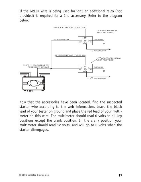
If the GREEN wire is being used for ign2 an additional relay (not<br />
provided) is required for a 2nd accessory. Refer to the diagram<br />
below.<br />
+12 VDC CONSTANT (FUSED 20A)<br />
ACCESSORY RELAY<br />
(NOT PROVIDED)<br />
TO ACCESSORY<br />
87<br />
86 87A 85<br />
30<br />
GROUND<br />
TO ACCESSORY<br />
+12 VDC CONSTANT (FUSED 20A)<br />
2 nd ACCESSORY RELAY<br />
(NOT PROVIDED)<br />
WHITE (+) 30A OUTPUT TO<br />
ACCESSORY CIRCUIT<br />
87<br />
86 87A 85<br />
30<br />
GROUND<br />
TO 2 nd ACCESSORY<br />
Now that the accessories have been located, find the suspected<br />
starter wire according to the web information. Leave the black<br />
lead of your tester on ground and place the red lead of your multimeter<br />
on this wire. The multimeter should read 0 volts in all key<br />
positions except the crank position. In the crank position your<br />
multimeter should read 12 volts, and will go to 0 volts when the<br />
starter disengages.<br />
© 2006 Directed Electronics<br />
17