Installation Instructions - Fire Dampers - NCA Manufacturing
Installation Instructions - Fire Dampers - NCA Manufacturing
Installation Instructions - Fire Dampers - NCA Manufacturing
- No tags were found...

Create successful ePaper yourself
Turn your PDF publications into a flip-book with our unique Google optimized e-Paper software.
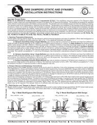
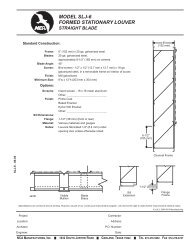
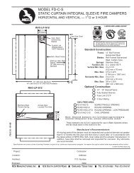
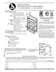
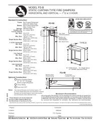
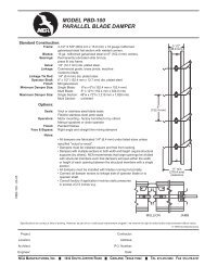
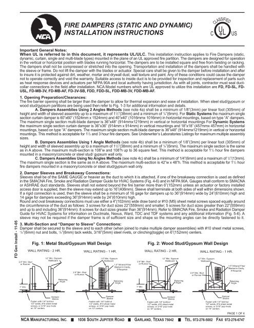
FIRE DAMPERS (STATIC AND DYNAMIC)INSTALLATION INSTRUCTIONSCCLASSIFIEDU L RUSFD Gen Install - 11-05Important General Notes:When UL is referred to in this document, it represents UL/ULC. This installation instruction applies to <strong>Fire</strong> <strong>Dampers</strong> (static,dynamic, curtain, single and multi-blade types) mounted in the plane of an UL approved fire partition. The dampers are designed for operationin the vertical or horizontal position with blades running horizontal. The dampers are to be installed square and free from twisting or racking.The dampers shall not be compressed or stretched into the opening. Transportation and installation of the dampers shall be handled withthe sleeve or frame. Do not lift the damper with the blades or actuator. Special care shall be given to the damper before installation and afterto insure it is protected against dirt, weather, mortar and drywall dust, wall texture and paint. Any of these conditions could cause the dampernot to operate correctly and void the warranty. Suitable access to inside duct is to be provided for inspection and replacement of parts suchas heat response devices and actuators per NFPA 90A and local authority having jurisdiction. As with all joints, contractor must seal ductcollarconnections in the field after installation. <strong>NCA</strong> Model numbers which are UL approved to utilize this installation are FD, FD-SL, FD-USL, FD-MB-3V, FD-MB-AF, FD-3V-SB, FDD, FDD-SL, FDD-MB-3V, FDD-MB-AF.1. Opening Preparation/Clearances:The fire barrier opening shall be larger than the damper to allow for thermal expansion and ease of installation. When steel stud/gypsum orwood stud/gypsum partitions are being used then refer to Fig. 1-3 for additional information and details.A. <strong>Dampers</strong> Assemblies Using 2 Angles Methods (see note 4a) shall be a minimum of 1/8”(3mm) per linear foot (305mm) ofheight and width of sleeved assembly up to a maximum of 1 1 /2”(38mm) and a minimum of 1 /4”(6mm). For Static Systems the maximum singlesection curtain damper is 60”x60” (1524mm x 1524mm) and 40”x40” (1016mmx 1016mm) in horizontal mountings, based on type “A” dampers.The maximum single section multi-blade damper is 36”x48” (914mmx1219mm) in vertical or horizontal mountings For Dynamic Systemsthe maximum single section curtain damper is 36”x36” (914mm x 914mm) in vertical mountings and 18”x18” (457mmx 457mm) in horizontalmountings, based on type “A” dampers. The maximum single section multi-blade damper is 36”x48” (914mmx1219mm) in vertical or horizontalmountings. This method is acceptable for 1 1 /2 and 3 hour fire dampers. See Underwriter’s Laboratories Listings for maximum multiple assemblysizes.B. <strong>Dampers</strong> Assemblies Using 1 Angle Methods (see note 4b) shall be a minimum of 1/8”(3mm) per linear foot (305mm) ofheight and width of sleeved assembly up to a maximum of 1 1 /2”(38mm) and a minimum of 1 /4”(6mm). The maximum single section is the sameas in A above. The maximum multi-section is 108”w and 108”h up to 36 square feet. This method is acceptable for 1 1 /2 hour fire dampersmounted in a masonry/concrete or steel stud/ gypsum wall only.C. <strong>Dampers</strong> Assemblies Using No Angles Methods (see note 4c) shall be a minimum of 1/4”(6mm) and a maximum of 1 /2”(13mm).The maximum single section is the same as in A above. The maximum multi-section is 42”w x 48”h. This method is acceptable for 1 1 /2 hourfire dampers mounted in a masonry/concrete or steel stud/gypsum wall only.2. Damper Sleeves and Breakaway Connections:Sleeves shall be of the SAME GAUGE or heavier as the duct to which it is attached, if one of the breakaway connection is used as definedin the SMACNA <strong>Fire</strong>, Smoke and Radiation Damper Guide for HVAC Systems (Fig. 4-6) and in NFPA 90A. Gauges shall conform to SMACNAor ASHRAE duct standards. Sleeves shall not extend beyond the fire barrier more than 6”(152mm) unless an actuator or factory installedaccess door is supplied, then the sleeve may extend up to 16”(406mm). Sleeve shall terminate at both sides of wall within dimensions shown.If a rigid connection is used, then the sleeve shall be a minimum of 16 gage for dampers up to 36”(914mm) wide by 24”(610mm) high and14 gage for dampers exceeding 36”(914mm) wide by 24”(610mm) high.Round and oval breakaway connections must use either a 4”(102mm) wide draw band or #10 (M5) sheet metal screws spaced equally aroundthe circumference of the duct as follows: 3 screws for duct sizes 22”(559mm) and smaller; 5 screws for duct sizes greater than 22”(559mm)and up to and including 36”(914mm): 8 screws for duct sizes greater than 36”(914mm). Refer to SMACNA <strong>Fire</strong>, Smoke and Radiation DamperGuide for HVAC Systems for information on Ductmate, Nexus, Ward, TDC and TDF systems and any additional information (Fig. 5-6). Asleeve may not be required if the damper frame is of sufficient size and shape so the mounting angles can be directly fastened to it.3. Multi-Section and “Damper to Sleeve” Connections:Damper shall be secured to the sleeve and to each other (when joined to make multiple damper assemblies) with #10 sheet metal screws,1/4”(6mm) nut and bolts, 1 /4”(6mm) tack welds, 3/16”(5mm) steel rivets, or clinching(toggle) on 6”(152mm) centers.2.5" Min. Studor RunnerFig. 1: Metal Stud/Gypsum Wall DesignWALL RATING - 2 HR.1/2" Min. GypsumWallboard2.5" Min. Studor RunnerWALL RATING - 1 HR.1/2" Min. GypsumWallboard1.5" Mineral FiberBlanket in Cavity,If Required2.5" Min. Studor RunnerFig. 2: Wood Stud/Gypsum Wall DesignWALL RATING - 2 HR.1/2" Min. GypsumWallboard2.5" Min. Studor RunnerWALL RATING - 1 HR.1/2" Min. GypsumWallboard1.5" Mineral FiberBlanket in Cavity,If RequiredRetainingAngleRetainingAngleRetainingAngleRetainingAngle1" Min.1" Min.DamperSleeveFasten with 1/4" bolt/nut1/2" welds, #10 sheet metalscrews, or 3/16" pop rivetson 10" centers.DamperSleeveFasten with 1/4" bolt/nut1/2" welds, #10 sheet metalscrews, or 3/16" pop rivetson 10" centers.DamperSleeveFasten with 1/4" bolt/nut1/2" welds, #10 sheet metalscrews, or 3/16" pop rivetson 10" centers.DamperSleeveFasten with 1/4" bolt/nut1/2" welds, #10 sheet metalscrews, or 3/16" pop rivetson 10" centers.PAGE 1 OF 4<strong>NCA</strong> MANUFACTURING, INC. 1036 SOUTH JUPITER ROAD GARLAND, TEXAS 75042 TEL. 972-276-5002 FAX 972-276-6747
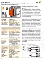
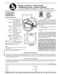
BREAKAWAY CONNECTIONSTraditional Breakaway Style Transverse JointsTransverse joints illustrated at right have always beenapproved as breakaway connections. SMACNA testinghas also approved the following variations as breakawayconnections.• Standing "S' joints can be applied with no. 10sheetmetal screws (through joint and duct) subject tothe following limitations: Maximum 2 screws in eachside and in bottom joint.• Transverse joints illustrated canbe applied as top and bottomjoints with Drive Slip - side jointsin duct heights up to 20 inches.(508 mm)Drive Slip JointPlain "S" Slip Hemmed "S" Slip Double "S" SlipInside Slip Joint Standing "S" Standing "S" (Alt.)Standing "S" (Alt.)Fig. 4Standing "S"(Bar Reinforced)Standing "S"(Angle Reinforced)Round and Oval Duct Breakaway ConnectionsRound or flat oval ducts connected to Type R, CR or CO damper collars may use no. 10 sheetmetal screws as follows:• Ducts to 22" (558 mm) wide (or dia.) and smaller may use 3 screws.• Ducts larger than 22" (558 mm) wide (or dia.) and up to 36" (914 mm) dia. may use 5 screws.• Ducts larger than 36" (914 mm) wide (or dia.) may use 8 screws.NOTE: When optional sealing of these joints is desired, the following sealants may be applied in accordance withthe sealant manufacturer's instructions: Design Polymerics - DP 1010.Manufactured Flanged SystemBreakway ConnectionsFlanged connection systems manufactured by Ductmate,Ward, and Nexus are approved as breakawayconnectionswhen installed as illustrated.(Attach permanufacturers'instructions)6" long 1/16" max.thickness plasticcleats 12" c-c (min.1 per side)Flanged systemanglesFig. 5<strong>Fire</strong> Damper SleeveDo not bolt cornersDuctNeoprene Gasketbetween all anglesProprietary Flange SystemBreakaway ConnectionsTDC and TDF systems are approvedas breakaway connections wheninstalled as described in the TDC orTDF addendum to the SMACNA DuctConstruction Standards except thecorners may not be bolted.Standard 6" (152 mm) metal clip maybe used with spacing as shownin diagram.Fig. 6SleeveDuctTypical TDC/TDF Joint60" Duct4 Reqd.Clip Spacing48" Duct3 Reqd.6"36" Duct3 Reqd.24" Duct2 Reqd.7"5"18" Duct &Smaller1 Reqd.5"Std. ClipLength6"CLDuct9"6"7"5"5"© 2005 <strong>NCA</strong> <strong>Manufacturing</strong>PAGE 3 OF 4<strong>NCA</strong> MANUFACTURING, INC. 1036 SOUTH JUPITER ROAD GARLAND, TEXAS 75042 TEL. 972-276-5002 FAX 972-276-6747
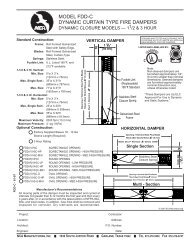
Fig. 7 – Two Angle (Two Sided) MethodRetainingAngle<strong>Fire</strong> WallSteel/Wood/Gypsum orMasonryAs Found in the UL <strong>Fire</strong>SleeveRetainingAngleStandard Turned Out AnglesFasteners<strong>Fire</strong> Rated PartitionTyp. 4Sides2"3.5"1.5"<strong>Fire</strong>DamperTurned-In Angles<strong>Fire</strong> Rated PartitionDamperSleeve<strong>Fire</strong> DamperSleeveFastenersFastenersRetainingAngleRetaining AngleMin. 1" OverlapAdditionalExpansionGapDamperSleeveRetainingAngle<strong>Fire</strong>DamperFig. 8 – One Angle (Single Sided) Method<strong>Fire</strong> WallSteel/Gypsum or MasonryAs Found in the UL <strong>Fire</strong>Resistance DirectorySteel/GypsumSleeveWallUL ApprovedWallRetaining DesignAngleFastenersSleeveFastenersRetainingAngleSteel/GypsumWallUL ApprovedWallDesignSleeveRetainingAngleFastenersMasonryWallSleeveDamperDamperDamperGrilleGrille MountUL ApprovedWall Design<strong>Fire</strong> DamperSteel SleeveGypsum3/4" Flange(Typ. 4 Sides)20 Ga. SteelFig. 9 – No Angle (Grille Mount) MethodGrille Mount "Out"Steel/Gypsum#10 Sheet MetalScrews, 6"oc.UL ApprovedWall DesignGypsum<strong>Fire</strong> DamperGypsum3/4" Flange(Typ. 4 Sides)20 Ga. SteelGrille Mount "In"Steel/Gypsum#10 Sheet MetalScrews, 6"oc.UL ApprovedWall DesignGypsum<strong>Fire</strong> Damper3/4" Flange(Typ. 4 Sides)20 Ga. SteelMasonry Walls#10 Self-TappingConcrete Anchors6" oc.Grille MountMasonryUL ApprovedWall Design<strong>Fire</strong> DamperThe multi-blade type fire damper installation is the same as the curtain blade type fire damper shown.This instruction sheet has been reviewed and accepted by Underwriters Laboratories.Manufacturer’s RecommendationsAll moving parts of the damper must be inspected and cycled at intervals not greater than every six months and in accordance withthe latest edition of NFPA 90A, 92A, local codes and the actuator manufacturer. In addition, fuse links shall be removed and inspectedNovember 2005 – FD Gen. InstallWhen UL is referred to in this document, it represents UL/ULC.PAGE 4 OF 4<strong>NCA</strong> MANUFACTURING, INC. 1036 SOUTH JUPITER ROAD GARLAND, TEXAS 75042 TEL. 972-276-5002 FAX 972-276-6747