Small Tool Instruments and Data Management
Small Tool Instruments and Data Management
Small Tool Instruments and Data Management
- No tags were found...

You also want an ePaper? Increase the reach of your titles
YUMPU automatically turns print PDFs into web optimized ePapers that Google loves.
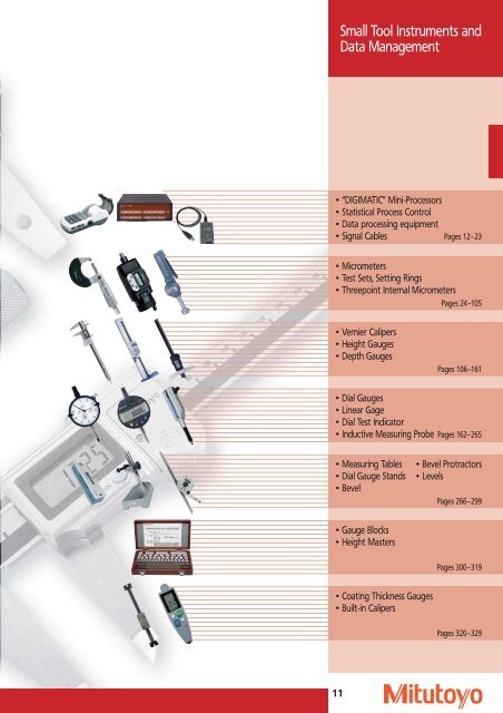
Basic information tostatistical process control SPC• Quality Control (abbreviated “QC”)Inspection, analysis <strong>and</strong> action applied to manufacturingoperation to economically achieve <strong>and</strong> maintain therequired level of quality of the product <strong>and</strong> service.Statistical quality control (abbreviated SQC) appliesstastitical techniques to quality control.• SubgroupTo investigate whether or not measurements are stable,samples are taken from the entire set of measurements<strong>and</strong> classified according to time, raw material, <strong>and</strong> otherfactors. Each set of samples is called a subgroup.• BIASThe difference between the mean (or estimated mean)of measurements <strong>and</strong> the expected value.• Control chartThe control chart shows the central tendency ofthe quality characteristics. It is used for effectivelyimplementing process control by determiningwhether a variation in quality is assignable to achange in process conditions or to r<strong>and</strong>om causes.A control chart consists of a center line (CL) <strong>and</strong>upper <strong>and</strong> lower control limit lines (UCL <strong>and</strong> LCL,upper <strong>and</strong> lower tolerance limits respectively) whichare determined based on the past performance ofthe manufacturing process. If the characteristicvalues plotted on the chart are between the upper<strong>and</strong> lower control limits <strong>and</strong> are free from abnormaltendencies, the process is considered to be undercontrol.• DispersionA measure of the variation of measurements. Thedegree of dispersion is usually quantified in termsof the st<strong>and</strong>ard deviation.Upper control limit(UCL)Center line(CL)Lower control limit(LCL)RunOutside the UCLTrend• SampleA collection of objects that are taken from a populationin order to investigate specific characteristics.• Sample sizeThe number of objects in a sample.• PopulationThe entire group of objects to which statistical analysisis applied.Purpose Population Sample(a) Actionapplied toprocessProcess controlProcess analysis(b) Actionappliedto lotsInspectionQualityestimationinfinitepopulationinfinitepopulationSamplingProcess Lot Sample <strong>Data</strong>ActionSampling measurementLot Sample <strong>Data</strong>Action• Process capabilityProcess capability is the reproducibility of the productwhen the process is under control <strong>and</strong> any assignablecauses of error have been removed.• _ XR chartThe _ XR chart is a combination of a _ X chart (which indicatesthe mean of each subgroup) <strong>and</strong> an R chart(which indicates the range of dispersion). It providesvery useful information for checking abnormal conditionsbased on the tendency of the mean <strong>and</strong> range ofsubgroups. It is often used for controlling the process interms of dimensions, yield, tensile strength, <strong>and</strong> otherquality characteristics of the product.• HistogramA graphical representation of the distribution ofmeasurements by means of rectangels whose widthsrepresents intervals into which the range (maximum –minimum) of observed values is divided <strong>and</strong> whoseheights represent the number of observations occurringin each interval (frequency). It provides an overview ofthe mean <strong>and</strong> the degree of dispersion. When theplotted points are distributed in a symmetrical, bellshapedform, it is called the normal distribution.FrequencyLower Specification Limit (LSL)Target ValueMeanBiasDispersion (± 3s)ToleranceUpper Specification limit (USL)RejectsMeasurements14
MeasurLink ®The complete solution for quality data processing with no limitsReal-Time_ Stat-MeasureOther productionlocationsCustomerQuality management<strong>Data</strong>baseProduct managerReal-Time-Plus_ Stat-Measure-PlusTesterTesterTesterTesterSuppliersInterfaceInterfaceCMMChannel Channel Channel1 2 3Channel Channel Channel1 2 3Process AnalyzerProcess ManagerUniversal compatibility with custom functionalityNow all-encompassing quality assurance is even moreefficient <strong>and</strong> convenient with measuring instrumentsfrom Mitutoyo <strong>and</strong> MeasurLink ® , the comprehensivesoftware for evaluating <strong>and</strong> exchanging quality data.MeasurLink ® supports all Mitutoyo digital measuringsystems – from calipers through to vision systems orcoordinate measuring machines.Even data from analogue devices can be easily integratedinto the process environment after manualacquisition.With its open program architecture, MeasurLink ® caneven process the measuring results from instrumentsfrom other manufacturers <strong>and</strong> incorporate them intoits own work processes. This places the user in a wholenew dimension of measured-data-assisted qualityassurance.With MeasurLink ® , all Mitutoyo measuring systems cannow be combined in a single quality analysis system.<strong>Data</strong> obtained from various instruments is collatedcentrally, evaluated <strong>and</strong> efficiently documentedaccording to need. This database is then available to allusers within the company, optimising quality assurance.It is completely irrelevant whether the measuringsystems networked with MeasurLink ® are concentratedin one site in the company or are scattered over severallocations – one important benefit for international users.What is more: the networking capabilities ofMeasurLink ® reach far beyond your own company.MeasurLink ® can also link your supplier’s Mitutoyomeasuring systems into its own data monitoring process,regardless of whether the supplier is based in theimmediate neighbourhood or on the other side of theworld, <strong>and</strong> no matter what type of measuring systemfrom the wide Mitutoyo range is used there.Gauge managementGage-RRPocket-ML15
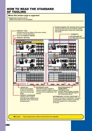
“DIGIMATIC” Mini Processor Type DP–1 VR• Mitutoyo's DP-1 VR is so compact, it fits right on your palm. But with this powerful little device you canprint data from calipers, micrometers <strong>and</strong> other measuring devices equipped with DIGIMATIC port <strong>and</strong>even perform statistical evaluations.• Printing speed is excellent, too, easy accessible with a one-touch start <strong>and</strong> with the built in thermal lineprinter there's almost no noise. The thermosensitive paper has outst<strong>and</strong>ing durability <strong>and</strong> chemical resistancefor long-term storage.• The DP–1 VR even lets you transmit the data to a computer using an RS–232 C connecting cable.• Easy printing function• Excellent readability due to large character print• Clock function for loading measuring data• Processing Capacity for up to 9.999 dataSeries 264No. 264–504 D (DP–1 VR)SpecificationsNo. 264–504 DPrinting method:Printing dot:Printing speed:Printing paper:Printing line:Processing capacity:Printing data:Output function:Input timer:Power:Battery life:DP–1 VRThermal line printer384 dot (8 dot / mm)6,5 mm/s(using AC adapter)48 mca. 6500 linesfor large charactersca. 12.000 lines for normalcharactersMode 1/2/3: 9.999 dataMode 0: 100.000 dataMeasurement data,GO/±NG judgment,number of data,maximum / minimum value,range, average,st<strong>and</strong>ard deviation,number of defective,fraction defective,process capability index,histogram,D-chart,control chartgeneration for Xd-bar <strong>and</strong>control limit data,date <strong>and</strong> timeOutput the measuring data(RS–232 C) or GO/±NGjudgment0,25 s; 1 s; 5 s; 30 s; 1 min;30 min; 60 min (0.25 sec. onlystatistical function)AC adapter 6 V(no interchangeable toDP-1 HS)Electric battery: LR-6 (alkaline),Ni-MH (rechargeable, batteriesare not charged in the device)10 years (clock battery),10,000 lines(1600 mA 1time/5 sec. usingthe nickel hydrofluoric battery)Operating temerature: (using AC adapter):0° to 45° C/(using battery):10° to 45° CStorage temperature: –10° to 50° CExample for application94 75.2St<strong>and</strong>ard accessoriesNo. 09EAA088 D AC adapterNo. 09EAA069 D Printer paper (1 roll)201Optional accessoriesNo. 937179 T FootswitchNo. 09EAA084 RS–232 C-Signal cable 1 m (9-Pin)for connection DP-1 VR to PCNo. 965516 GO/NG CableNo. 09EAA094 RS–232 C-Signal cable 1 m (25-Pin)For DP-1 VR connection to displayGlass scale KS/KC/KL/KLL/KA43.9Consumable SparesNo. 011037 LR-6 batteries (4 pieces)No. 011348 NI-MH-batteries (rechargeable)No. 09EAA082-5 Printer paper (5 rolls)No. 937179 TDimensions in mm16
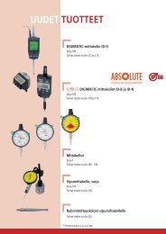
“DIGIMATIC” Mini Processor Type DP–1 VRSeries 264Lower limitUpper limitInput dataProcess capability indexAverageRangeNumber of dataNumber of devisionof the histogramUpper control limit( _ X control)Lower control limit( _ X control)Upper control limit(R control)Lower control limit(R control)Key functionsPRINTER ON/OFF Mode 0 Mode 1, 2CLOnly measurement data clear. Press before setting limit.CECancel the previous measurement data.TOL.LIMITPress before entering or finish the upper/lower measurement mode.Cancel measurement mode.STAT Do not operate Making histogram to printout thecalculation result via statistical analysisFEEDPrinter paper is fed when this key is pressedDATAEnter data via measuring devicesPRINTER ON/OFFControls the printer’s ON/OFF statusPOWERPower ON/OFFMode 3Subgroup in measurementSubgroup after measurementCL Reentering from data No. 1 Only measurement data clear.CE Cancel previous measurement data. Cancel previous subgroup.TOL.LIMIT Exiting the measurement. Go to next subgroup measurement.STAT Finish the subgroup measurement. Print out <strong>and</strong> calculate the control limitPrintout the X-R calculation result.value from each subgroup to completeFEEDPrinter paper is fed when this key is pressedDATAEnter data via measuring devicesPRINTER ON/OFFControls the printer’s ON/OFF statusPOWERPower ON/OFF17
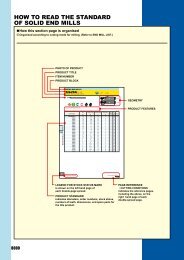
“DIGIMATIC” Signal Cables• Mitutoyo’s “DIGIMATIC”-format allows for connecting not only numerous additional devices,such as printers, counters <strong>and</strong> the like, but also for connecting one or more “DIGIMATIC”-measuringinstruments to an external PC employing a Mitutoyo transmitter with RS-232 C signal cable.“DIGIMATIC” measuring instruments requireeither of the following items for data transmission:1. Footswitch2. <strong>Data</strong> key on the instrument (if present)3. <strong>Data</strong> request from the PC4. Signal cables with data key(if connectable to the measuring instrument)Plug connectors to themeasuring instrumentsPlug connectors to the peripherals(DMX transmitters or data printers)Order No.1 m 2 m905338 905409905689 905690905691 905692905693 905694PortApplication withA DIGIMATIC Dial Indicator Type IDS (Series 543)A DIGIMATIC Dial Indicator Type IDC (Series 543)A DIGIMATIC Dial Indicator Type IDU (Series 575)A DIGIMATIC Thickness gauge (Series 547)A DIGIMATIC Caliper (Series 500 with the exception ofIP-65/66/67 calipers, Series 550, 551, 573)“DIGIMATIC” Workshop Caliper (Series 552)“DIGIMATIC” Height gauge (Series 192, 570)A DIGIMATIC Depth gauge (Series 547)Portabel hardness testing devices (Series 811)A DIGIMATIC inside measuring device Bore Gage (Series 511)Measurement instrumentsSignal cable plugsStraight (without data key)Back side (without data key)Right (without data key)Left (without data key)959149 959150A DIGIMATIC Depth gauge (Series 571)“DIGIMATIC” Built-in Caliper (Series 572)with data key05CZA66205CZA663“DIGIMATIC” Micrometer (Series 293, 314, 317, 323, 324, 326, 331,340, 342, 369, 389, 395, 422“DIGIMATIC” Micrometer heads (Series 350)“DIGIMATIC” Depth micrometer (Series 329)“DIGIMATIC” Inside micrometer with jaws (Series 345)with data key <strong>and</strong> screws05CZA62405CZA625IP-65/66/67 A DIGIMATIC Thickness gauge (Series 500)IP-67 A DIGIMATIC Depth gauge (Series 571)with data key <strong>and</strong> screws937387 965013937386 965012936937 965014A Quick Micrometer (Series 227, 293)“DIGIMATIC” Micrometers (Series 293, 314, 317,323, 324, 326, 331, 340, 342, 343, 369, 389, 395, 406, 422)“DIGIMATIC” Micrometer heads (Series 164)“DIGIMATIC” St<strong>and</strong>ard micrometer (Series 121)“DIGIMATIC” Inside micrometer (Series 337, 339)Three-point inside micrometer ”DIGIMATIC-Holtest” (Series 468)A DIGIMATIC Borematic (Series 568)Height Micrometer “Heightmaster” (Series 515)Stationary hardness tester “Wizhard” (Series 810)Stationary hardness tester “Micro Vickers HM” (Series 810)Stationary hardness tester “Micro Vickers HV” (Series 810)HH-120/140 Portable hardness tester (Series 810)ATK Stationary hardness tester (Series 810)ARK Stationary hardness tester (Series 810)A DIGIMATIC Dial Indicator Type ID-F (Series 543)“DIGIMATIC” Dial Indicator Type ID-H (Series 543)Portable surface roughness tester SJ-201 P / S / PR (Series 178)Portable surface roughness tester SJ-301/ S / PR (Series 178)Portable surface roughness tester SJ-401/SJ-402 (Series 178)Profile projector PJ-Series (Series 303)Profile projector PH-Series (Series 172)Height Micrometer “CERA-Heightmaster” (Series 515)Linear Height Gage “Linear Height” (Series 518)Height gauge QM-Height (Series 518)“Mm-Checker” Electronic length measuring instrument (Series 519)LINEAR GAGES Counter (Series 542)LSM-6000 Counter for Laser Scan Micrometer (Series 544)Laser-Scan Micrometer LSM 9506“DIGIMATIC” Multi-unit (Series 572)„LITEMATIC“ VL-50 (Serie 318)6 Pins (without data key)10 Pins (without data key)Identical connectorson both ends(without data key)18
“DIGIMATIC” Signal Cables• Mitutoyo’s “DIGIMATIC”-format allows for connecting not only numerous additional devices,such as printers, counters <strong>and</strong> the like, but also for connecting one or more “DIGIMATIC”-measuringinstruments to an external PC employing a Mitutoyo transmitter with RS-232 C signal cable.“DIGIMATIC” extension cableNo. 011393LengthNo.5 m 0113918 m 01139210 m 011393DIGIMATIC measurement deviceswith data outputDIGIMATIC Transmitteror DIGIMATIC MiniprocessorDIGIMATIC Signal cableto the measuring instruments1 m or 2 mNo. 011391 5 mNo. 011392 8 mNo. 011393 10 mDIGIMATIC Signal cableNo. 936937 1 mNo. 965014 2 m“DIGIMATIC” <strong>Data</strong> transmitterInterface parametersSoftware compatibility: Windows 98Windows 2000Windows MEWindows XPPocket PC 2002“DIGIMATIC” USB interface“DIGIMATIC” USB interface for connecting a “DIGIMATIC” measuring instrument to a PC-USB interfacefor direct reading into an application software such as Microsoft Excel.Optional accessoryNo. 937179 T FootswitchNo. 264–01419
“DIGIMATIC” DMX-Transmitters• Measuring device interface for transmitting measured values from Mitutoyo measuring instrumentsinto appropriate application programs. The instrument communicates with the PC via a driverprogram generally included with the CAQ software. The application defines what measuring devicesare to be read in, how often the measurement is to be repeated etc.Type DMX–1 serialNo. 011216 DMX–1Type DMX–1 USBNo. 011442 DMX–1 USBType DMX–2 serialNo. 011189 DMX–2Type DMX–2 USBNo. 011443 DMX–2 USBType DMX–3The DMX–1 serial is a microcontrolled interface for connectinga measurement device with “DIGIMATIC” interface to anexternal computer featuring RS–232 C interface. The deviceworks without external power supply (The h<strong>and</strong>shake linesRTS <strong>and</strong> DTR are necessary for the power supply.)Incl. footswitch connector*.* <strong>Data</strong> transfer can be initiated with footswitch available asoptional accessory.The DMX–1 USB is a microcontrolled interface for connectinga measurement device with “DIGIMATIC” interface to anexternal computer featuring USB interface. The devicereports as “virtual” RS-232 C interface to the computer.Incl. footswitch connector*.* <strong>Data</strong> transfer can be initiated with footswitch available asoptional accessory.The DMX–2 serial is a microcontrolled interface for connectingtwo measurement devices with “DIGIMATIC” interface tothe RS-232 C interface of a computer. The device workswithout external power supply (The h<strong>and</strong>shake lines RTS <strong>and</strong>DTR are necessary for the power supply.)<strong>Data</strong> transfer can be initiated with footswitch <strong>and</strong> adapterfor footswitch available as optional accessory.The DMX–2 USB is a microcontrolled interface for connectingtwo measurement devices with “DIGIMATIC” interface to theUSB interface of a computer. The device reports, dependingon setting as “virtual” RS-232 C interface or as keyboard tothe computerIncl. footswitch connector*.* <strong>Data</strong> transfer can be initiated with footswitch available asoptional accessory.Das DMX–3 allows for connecting three measurementdevices featuring “DIGIMATIC” interfaces to the RS–232 Cinterfaces. Power supply with AC/DC adapter (st<strong>and</strong>ardaccessory).Incl. footswitch connector*.* <strong>Data</strong> transfer can be initiated with footswitch available asoptional accessory.No. 011253Interface parametersTypeDMX–1 serialNo. 011216<strong>Data</strong> output:(D-SUB 9) RS–232 CNumber of input channels: 1Baud rate:9600 Baud<strong>Data</strong> bits: 8Stop bits: 1Parity:noneTypeDMX–1 USBNo. 011442<strong>Data</strong> output:USB with RS–232 C (serial)EmulationNumber of input channels: 1Optional accessoriesNo. 011196 Connecting cable for computerD-SUB 9 – D-SUB 9 (2 m)No. 937179 T FootswitchInterface parametersTypeDMX–2 serialNo. 011189<strong>Data</strong> output(D-SUB 9) RS–232 CNumber of input channels: 2Baud rate:9600 Baud<strong>Data</strong> bits: 8Stop bits: 1Parity:noneTypeDMX–2 USBNo. 011443<strong>Data</strong> output:USB with RS–232 C (serial)or probe EmulationOptional accessoriesNo. 011197 Connecting cable for computerD-SUB 25 – D-SUB 9 (0,2 m)No. 011119 Connecting cable for computerD-SUB 25 – D-SUB 9 (2 m)No. I–1502067 Connecting cable for computerD-SUB 25 – D-SUB 25 (2 m)No. 011193 Adapter for footswitchNo. 937179 T Footswitch011193Interface parametersTypeDMX–3No. 011253<strong>Data</strong> output:(D-SUB 9) RS–232 CNumber of input channels: 3Baud rate:1200/9600 Baud(adustable with jumper)<strong>Data</strong> bits: 8Stop bits: 1Parity:noneOptional accessoriesNo. 011196Connecting cable for computerD-SUB 9 – D-SUB 9 (2 m)No. 937179 T FootswitchNo. 011444 Adapter cable USB to RS-232C20
Interface parametersType DMX 4–1No. 011319<strong>Data</strong> output:(D-SUB 9) RS–232 CNumber of input channels: 4 / 2Baud rate:9600 Baud<strong>Data</strong> bits: 8Stop bits: 1Parity:noneRS-232 C connection options of:• Layer thickness measuring device :DIGI-DERM 1100 / 2100• Laser Scan Micrometer: LSM 5000 / 6000• Linear scale display: KS counter (1 axis, 2 axes)+ KA counter• Contact arm dial gauge series 209• EF display for linear gauge• QM-Height• Linear Height LH–600 B / C / CG• Sartorius Balance MC 1• Mettler Balance PM 3000• Kern Balance 510Optional accessoriesNo. 011196 Connecting cable for computerD-SUB 9 – D-SUB 9 (2 m)No. 937179 T FootswitchRS-232 C connection cable for DMX 4-2No. 011338 DIGI-DERM 1100/2100No. 011339 KS counter + KA counterNo. 011340 EF-P counter, laser; LH-600 B / C / CGNo. 011341 Contact dial gauge series 209No. 011342 St<strong>and</strong>ard Opto RS-232No. 011343 Sartorius MC1 balance, Mettler balanceNo. 011344 Core 510 balanceNo. 011387 QM height“DIGIMATIC” DMX-Transmitters• Measuring device interface for transmitting measured values from Mitutoyo measuring instrumentsinto appropriate application programs. The instrument communicates with the PC via a driverprogram generally included with the CAQ software. The application defines what measuring devicesare to be read in, how often the measurement is to be repeated etc.Type DMX 4–2The DMX 4–2 is an interface that allows for connecting four “DIGIMATIC” measuring instruments <strong>and</strong> two measuringinstruments with Multi-RS-232 Interface to a PC with RS-232 C Interface.The DMX 4-2 takes on the following functions:1. Adaptation of the signal level of the measuring device to the requirements of the serial interface2. Translation of the various measurement signals into a common format3. Communication between measuring devices <strong>and</strong> PC (channel selection etc.)Incl. footswitch connector*.* <strong>Data</strong> transfer can be initiated with footswitch available as optional accessory.Type DMX–8; DMX–16No. 011319The DMX–8 <strong>and</strong> DMX–16 are interfaces for connecting measurement devices featuring “DIGIMATIC” ports tothe RS–232 C interface of an external computer. Power supply 220 V–240 V 50 Hz. Incl. footswitch connector*.* <strong>Data</strong> transfer can be initiated with footswitch available as optional accessory.Interface parametersTypeDMX–8No. 011190<strong>Data</strong> output(D-SUB 9) RS–232 CNumber of input channels: 8Baud rate:9600 Baud<strong>Data</strong> bits: 8Stop bits: 1Parity:noneInterface parametersTypeDMX–16No. 011191Number of input channels: 16As for DMX–8Interface parametersTypeDMX–16 CNo. 011255As for DMX-16Type DMX–16 CNo. 011190The DMX–16 C features integrated microprocessors for data processing, thus enabling simultaneous inputfrom all measurement instruments <strong>and</strong> increasing data processing speed.For the Dial indicators Series 575 integrated power supply <strong>and</strong> a ABS-ZERO key are made available.Incl. footswitch connector*.Optional accessoriesNo. 011196 Connecting cable for computer(2 m)No. 937179 T FootswitchNo. 01125521
“DIGIMATIC” DMX-TransmittersType DMX–3 T USBKeyboard interfaceThe measurement converter DMX–3 T USB allows for connection of three “DIGIMATIC” measurement instrumentsto the keyboard interface of an IBM-compatible computer. Thus applications asking for manual input of measurementdata only (such as spread sheet calculation, word processing) are being provided with the respective interface.After the operator initiates data transmission the DMX–3 T USB simulates the keyboard input from the measurementdevice. The keyboard remains operative.Interface parametersTypeDMX–3 T USBNo. 011192Number of input channels: 3<strong>Data</strong> output: USB keyboard /PS2 keyboardSt<strong>and</strong>ard accessoryKeyboard cable for PS2 keyboardConnection: USB cable for direct connectionto PC-USBNo. 011192No. 011192Type DMX–3 T/FS USBKeyboard interfaceSpecifications same as DMX–3 T USB, but the measured values can only be trigged via footswitches.The footswitch is available as a special accessory.Interface parametersTypeDMX–3 T/FS USBNo. 011220Number of input channels: 3<strong>Data</strong> output: USB keyboard /PS2 keyboardOptional accessoryNo. 937179 T FootswitchNo. 011220St<strong>and</strong>ard accessoryKeyboard cable for PS2 keyboardConnection: USB cable for direct connectionto PC-USBNo. 011220“DIGIMATIC” Switch BoxThe measurement switch box allows for connecting up to five “DIGIMATIC” measurement devicesto a single “DIGIMATIC”-<strong>Data</strong> processor (e. g. DMX–1).Interface parametersTypeSwitch boxNo. 011235Number of input channels: 5<strong>Data</strong> output:“DIGIMATIC”Optional accessoriesNo. 936937 Signal cable (1 m)No. 526688 D AC/DC adapter (9 V, 500 mA)No. 937179 T FootswitchNo. 01123522
“DIGIMATIC” Transmitters DL-1000 / DL-1000 M• The “DIGIMATIC” DL-1000 / DL-1000 M are data logger for storing measurement data that have beenrecorded by a “DIGIMATIC” measuring to be output to a computer.• The measuring device is connected to the I/O port of the DL 1000 / DL-1000 M with a data cable <strong>and</strong>the measurement data are being transferred with the data switch on the measuring device or theDL 1000 / DL-1000 M.• For data transfer to the computer the devices are hooked up to an interface connection with thecomputer. (See pages 20–22).• <strong>Data</strong> transfer from the DL 1000 / DL-1000 M are being executed with the data or footswitch of aninterface or upon request from the respective software.With regards to the interfaces of the measurement devices the DL 1000 / DL-1000 M acts like a“DIGIMATIC” measurement instrument.• <strong>Data</strong> can be output directly to a connected printer with “DIGIMATIC” interface.Type DL-1000 / DL-1000 MSpecificationsType DL-1000No. 011264Type DL-1000 MNo. 011264 MDimension: 120 x 60 x 26 mmMass: 130 gMemory(DL-1000 / DL-1000 M): Up to 999 measurementvalues can be stored by the data loggers.(DL-1000 M): Sample or feature related operationis possible.A maximum of 100 features from 9 samples canbe loaded. If the number of features is reduced,the available number of samples is increased.Based on the number of features, the DL-1000 Mwill calculate automatically how many samples areavailable.If, e. g., you want to measure 10 features, you canchoose a maximum of 99 samples.<strong>Data</strong> formatAll data are loaded or output in Mitutoyo“DIGIMATIC” compatible format.Connection to measuring instrumentsTo output measurement values, DL-1000/DL-1000 Mcan be connected to any interface or protocolprinter which allow for connecting Mitutoyo“DIGIMATIC” compatible measuring instruments.St<strong>and</strong>ard accessories:1 battery (9 V) block LithiumSignal cable 10 pole to 10 pole (0.25 m)Optional accessories:No. 936937 Signal cable (1 m)No. 965014 Signal cable (2 m)No. 011264 / No. 011264 MKeys <strong>and</strong> functionsDepending on the selected mode the keys of the Digi-Log enable the following functions:IDTDTDTIIDTI IIMeasuring modeTransfers the actual value at the cursor positionto the Digi-Log.Same function as data switch on measuring device.The DL-1000/DL-1000 M is turned off after 4 sec.Scrolls the list of measured data up or downby one value.Scrolls the list of measured data up or downby 50 value.Switches to output mode.Output modeTransfer the displayed value of the Digi-Log to aninterface or printerThe DL-1000/DL-1000 M is turned off after 4 sec.Scrolls the list of measured data up or downby one value.Scrolls the list of measured data up or downby 50 value.Switches to measurement mode.Mode < Erase memory? > Mode < Erase memory? >INo Yes No YesSwitches to block creationAll measurement values starting with the current(DL-1000 M only).position are output in 0,6 sec cycles.Not used.IIIIIIIAll measurement values starting with the currentposition are output in 1,1 sec cycles.23