Full-scale fire truck performance measurements - Department of ...
Full-scale fire truck performance measurements - Department of ...
Full-scale fire truck performance measurements - Department of ...
- No tags were found...

You also want an ePaper? Increase the reach of your titles
YUMPU automatically turns print PDFs into web optimized ePapers that Google loves.
<strong>Full</strong>-<strong>scale</strong> Fire Truck Performance MeasurementsP.A. Bowditch, J. E. Leonard, D.J. O’BrienCSIRO Manufacturing & Infrastructure Technology, Highett, Victoria, AustraliaAbstractThe deaths <strong>of</strong> <strong>fire</strong>fighters in the Wingello <strong>fire</strong>s in New South Wales awakened a need for <strong>fire</strong><strong>truck</strong> design in Australia to be reviewed. Protection <strong>of</strong> <strong>fire</strong> crews in a bush<strong>fire</strong> burnover isparamount. With this in mind, CSIRO was employed by the Country Fire Authority <strong>of</strong>Victoria and the Rural Fire Service <strong>of</strong> New South Wales to identify those parameters whichcould be used as <strong>truck</strong> <strong>performance</strong> criteria. A test method was developed and 24 full-<strong>scale</strong>tests allowing the measurement <strong>of</strong> radiation, temperature and toxic gases were performed.The results <strong>of</strong> these tests will reflect future <strong>fire</strong> <strong>truck</strong> designs. This paper aims to discuss thetest method and modifications carried out to the <strong>truck</strong>s to improve their <strong>performance</strong> in abush<strong>fire</strong> burnover.IntroductionBush<strong>fire</strong>s in recent years and their potential to harm a community’s infrastructure, as well asthe potential for loss <strong>of</strong> life, has led all to rethink existing practices relating to bush<strong>fire</strong> safety.As frontline <strong>fire</strong>fighters are most at risk in the event <strong>of</strong> a bush<strong>fire</strong> burnover, the question wasposed as to whether the protection afforded by a <strong>fire</strong>fighting vehicle was sufficient.As a result, two Australian <strong>fire</strong>fighting authorities – the Country Fire Authority <strong>of</strong> Victoria(CFA) and the Rural Fire Service <strong>of</strong> New South Wales (RFS) – commissioned CSIRO tohelp them identify the parameters <strong>of</strong> importance in protecting <strong>fire</strong>fighters and their vehicles.In addition, the modifications made to the <strong>truck</strong>s, which included shielding and water sprays,and their effectiveness were assessed. CSIRO Forestry & Forest (FFP) products supplied thetheory and measurement relating to the bush<strong>fire</strong> flame front, whilst CSIRO Manufacturing &Infrastructure Technology (CMIT) supplied the onboard measurement <strong>of</strong> <strong>fire</strong> <strong>truck</strong><strong>performance</strong> during testing.A series <strong>of</strong> 24 tests were carried out on an artificial flame front simulator built at the RFS’sHot Test Fire Facility at Mogo, New South Wales, Australia (Figure 1). This simulator wascommissioned by gas experts Gameco Pty Ltd. Background information for the design wassupplied by FFP, and from work done by CSIRO and Gameco on the Australian DefenceIndustries (ADI) testing done at Fiskville in Victoria on their Fireking <strong>truck</strong>. ADI made thebackground information available for the development <strong>of</strong> the Mogo tests. Trucks from bothauthorities were tested by applying various <strong>fire</strong> intensities and comparing the results fromboth sprayed and unsprayed vehicle tests. Further information on the experimental setup anddiscussion <strong>of</strong> results can be found in (Nichols et al. 2003) and (Sullivan et al. 2003).
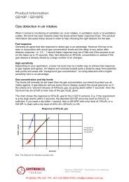
Figure 1. A <strong>truck</strong> on the gas-<strong>fire</strong>d simulator test bedMeasurements were taken <strong>of</strong> critical parameters for life safety within the cabin, such astemperatures and radiant heat, as well as toxic gas emissions (Brown et al. 2003). Thermalfactors for human survival were calculated (Knight et al. 2004). The measurement <strong>of</strong> theeffects <strong>of</strong> a flame front on <strong>fire</strong> <strong>truck</strong>s had never been done before. The development <strong>of</strong>systems <strong>of</strong> measurement that could provide useful data whilst being able to withstand theadverse effects <strong>of</strong> <strong>fire</strong> was a challenge.This aim <strong>of</strong> this paper is to give an overview <strong>of</strong> the test methodology employed by CMIT inrelation to equipment for temperature and radiation measurement.Temperature MeasurementsAll temperatures, whether internal or external, were measured using 1.5 mm ‘K-type’ MIMS(mineral insulated metal sheath) thermocouples with unearthed tips and an inconel sheath. K-type thermocouples have been commonly used in our <strong>fire</strong> research as they have a temperaturerange up to 1250°C. Figure 2 shows a typical radiometer and thermocouple.Thermocouples contain two dissimilar metal wires which are joined at the tip and create anelectrical circuit that creates an electromotive force that can be measured and equated to atemperature. Thermocouples have a MIMS length as well as PVC- or teflon-coated lead andcan be made to any length. In addition, they can be supplied with a fibreglass-coated leadwhich we chose for its higher temperature rating. The MIMS length <strong>of</strong> the lead has a highertemperature rating than the rest <strong>of</strong> the lead and, as a result, it was decided to use longerMIMS in regions where flame immersion <strong>of</strong> the thermocouples was an issue.Thermocouples could be easily tested after installation by heating their tips and observingdata on the computer or by testing them with multimeters. Many multimeters now have amini plug connection for K-type thermocouple inputs. These thermocouples also have aresistance between the wires <strong>of</strong> approximately 8 ohms, which is also a useful technique tocheck for bad connections or to determine whether there is a break in their length.
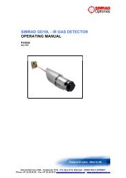
Figure 2. A typical radiometer and thermocoupleTemperatures where measured predominately in-cab as this was the information mostpertinent to occupant comfort. Figure 3 shows typical locations <strong>of</strong> internal thermocoupleduring testing. External <strong>truck</strong> temperatures were measured on the driver mirrors, wheel wellsand at several external locations. Temperatures were also measured in the ROPS or rear cabon vehicles where this was an addition.Internal temperatures were measured on all window, ro<strong>of</strong>, door, floor and wall surfaces.Passenger-side air temperatures were measured at head, chest and seat heights as in all tests,this was the side <strong>of</strong> the <strong>truck</strong> from which the simulated <strong>fire</strong> front approached.Figure 3. Truck side thermocouple locations
Figure 5. External on-<strong>truck</strong> radiometer (passenger side)DataloggingAll temperature and radiation data was collected by a datalogger, which allowed multichanneldata collection <strong>of</strong> analogue or digital inputs, and also allowed for digital switching <strong>of</strong>items such as relays. The units used were Datataker 505s with the addition <strong>of</strong> expansionmodules to increase the base unit’s logging capabilities, allowing the collection <strong>of</strong> data from76 channels. Figure 6 shows the complexity <strong>of</strong> such multichannel wiring. Datatakers have onboardmemory cards and can simultaneously stream data to any computer .Figure 6. Datataker and associated wiring in-situ
On sending logging routines to the Datataker, they can run indefinitely as long as battery lifeallows. In the Mogo tests, we wanted all the data logged at 5-second intervals and to berecorded on the memory card for back-up, as well as being streamed live during theexperiments to an external computer. The addition <strong>of</strong> an external computer allowed us toconstantly monitor the status <strong>of</strong> the vehicle and the integrity <strong>of</strong> the logging system. Data wasretrieved as text delimited, so it is easy to transfer it to programs such as Micros<strong>of</strong>t Excel fordata manipulation and graph plotting.In initial tests, the external feed <strong>of</strong> data was via an underground cable from the datataker tothe logging computer in the control room; this was modified in later tests. The umbilicalcable from <strong>truck</strong> to test bed, as well as all other external cabling, was heavily wrapped inKaowool and aluminium tape. Kaowool is a mineral fibre wool with a high temperaturerating that acts as an insulator.All tests were extensively photographed and videotaped. The use <strong>of</strong> digital cameras allowedfor the easy inclusion <strong>of</strong> photos in reports, as well as allowing easy back-up to CD or DVD.Digital videos allowed for easy transfer to all mediums, and also enabled post-editing <strong>of</strong>footage for presentations.A Better Datalogging SystemExpensive scientific equipment <strong>of</strong>ten intended to be used ‘on bench’, does not take kindly tothe abuse that a bush<strong>fire</strong> burnover may deliver it. Some equipment failures during the testsled to us finding better means <strong>of</strong> maintaining equipment integrity. It was decided to make alldata collection equipment autonomous from the test bed, and to sever all hard line externalconnections and replace them with a much improved system.Extremes <strong>of</strong> temperature damaged some <strong>of</strong> the sensors in initial tests. Water penetration intothe joints <strong>of</strong> in-ground cabling was also a problem. There was also failure <strong>of</strong> the umbilicalfrom ground to <strong>truck</strong> cabin due to flame damage. Although these problems did not result insignificant data loss, the use <strong>of</strong> standard electrical flex, high-temperature silicon joints andthe cable insulation employed was clearly inadequate. The downtime <strong>of</strong> cable failuresreduced the turnaround time <strong>of</strong> tests, which was <strong>of</strong> particular annoyance when weatherconditions were favourable. All cabling was replaced by silicone-coated leads, which have ahigher temperature rating. All external cables were placed in a sheathing <strong>of</strong> Firemaster thathad similar temperature and flame immersion ratings as the previous methods but was farquicker to install. In extreme areas, stainless steel flexible sheathing (see Figure 7) was usedto provide additional flame impingement protection.It was decided to protect the datataker system in a ¼’’ steel <strong>fire</strong>pro<strong>of</strong> box which was linedwith a mineral fibreboard. We considered water cooling or placing icepacks in the box, butdismissed this idea because <strong>of</strong> the potential for shorting or earthing problems with electroniccomponents due to water condensation.In early tests, the datataker was supplied by small 12 V sealed batteries, but these werereplaced with larger battery banks, which reduced the potential <strong>of</strong> low battery voltage duringor between tests. Batteries were ‘trickle’ charged from an external source between tests tomaintain their supply. These were also placed in the <strong>fire</strong>pro<strong>of</strong> box due to the potentiallyexplosive nature <strong>of</strong> the batteries with overheating or flame contact.
Figure 7. Protected data transmission cablingA radio modem system (Figure 8) was incorporated to provide the external data streamingrather than rely on a hard-wired communication cable between the datataker and the loggingcomputer in the control room. The radio modem has a range <strong>of</strong> 3 km in a straight line, andoperates at a frequency <strong>of</strong> 2.5 Ghz. The system is such that the receiver and transceivercontinuously monitor each other so that if communication is broken, they will automaticallyreconnect after finding each other. Any data that was to be transferred during this period <strong>of</strong>lost communication is buffered in the logger and sent as soon as communication isre-established.Figure 8. Radio modem transmitter
Better Sensor ConfigurationRadiometers now have on-vehicle water reserves which are pumped by small submersiblepumps powered by 12 V batteries. The submersion <strong>of</strong> these pumps keeps them cool, allowingthem to operate within manufacturer’s specifications.Measurement <strong>of</strong> Fire Front From Vehicle’s PerspectiveIn addition to all equipment previously described, we have now employed a 5 m swing-outboom, which allows us to deploy measuring equipment into the flame front before it reachesthe vehicle. This also allows equipment to be sufficiently away from the vehicle to be littleeffected by spray systems, and thus the flame front without any suppression effects can bemeasured. The water from spray systems has a clouding and cooling effect on someinstruments, flame or smoke.From the boom we have deployed specialised radiation, soot and smoke meters, designedin-house, which provide further information on the characteristics <strong>of</strong> flame fronts, whetherthey be natural such as leaf litter and native grasses, or whether man-made such as theartificial gas <strong>fire</strong>s produced by flame-front simulators. These specialised sensors measureflame properties such as emissivity and radiant heat as a function <strong>of</strong> flame depth. Theunderstanding <strong>of</strong> these specific aspects <strong>of</strong> a flame front are essential in determining the wayin which a <strong>fire</strong>fighting vehicle is impacted by different types <strong>of</strong> <strong>fire</strong> fronts.We are in the process <strong>of</strong> installing a sacrificial camera on the boom which we anticipate willrecord most <strong>of</strong> the <strong>fire</strong> event before being heat effected. The video from this camera will belive fed via a radio link to a computer some 200 m away from the vehicle, allowingobservation <strong>of</strong> the <strong>fire</strong> event and providing a safe back-up <strong>of</strong> video footage.We now use engine analyser units to observe the effects <strong>of</strong> smoke and temperature on the<strong>performance</strong> <strong>of</strong> both <strong>truck</strong> engines and water pumps during a <strong>fire</strong> event.The addition <strong>of</strong> McCaffrey probes allows us to measure the wind speeds <strong>of</strong> a <strong>fire</strong> front atvarying heights around the vehicle. These probes measure differential pressure which is thenconverted to a wind speed via Bernouli’s equation.Radiometers have been placed on 2 m high towers above the vehicle’s rear tray to measurethe potential radiation effects from gas plumes above the vehicle.A 15 m high tower has been placed on the rear <strong>of</strong> the <strong>truck</strong> which has thermocouples attachedat 3 m intervals, giving us the opportunity to measure the temperature gradient <strong>of</strong> the gasplume above the vehicle.ConclusionFinetuning <strong>of</strong> on-board systems and the addition <strong>of</strong> other measurement devices is an ongoingprocess, but now we have a solid grounding in quantifying the effects a flame front has on avehicle during a burnover.
ReferencesBrown, S.K. et al. 2003. Air toxics factors and criteria for crew survivability/tenability invehicle burn-over. Presented to 3rd International Wildland Fire Conference, 3–6 October,Sydney, Australia.Knight, I. et al. 2003. Thermal factors for human survival in <strong>fire</strong> tanker burn-overs. Presentedto 3rd International Wildland Fire Conference, 3–6 October, Sydney, Australia.Nichols, D. et al. 2003. Development <strong>of</strong> <strong>fire</strong> fighting vehicle crew protection systems.Presented to 3rd International Wildland Fire Conference, 3–6 October, Sydney, Australia.Sullivan, A. et al. 2003. Experiments to evaluate the effectiveness <strong>of</strong> <strong>fire</strong> vehicle protectionsystems using a gas-fuelled bush<strong>fire</strong> flame front simulator. Presented to 3rd InternationalWildland Fire Conference, 3–6 October, Sydney, Australia.