The Application of Intrinsic Safety to Fieldbus Systems - ICEWeb
The Application of Intrinsic Safety to Fieldbus Systems - ICEWeb
The Application of Intrinsic Safety to Fieldbus Systems - ICEWeb

You also want an ePaper? Increase the reach of your titles
YUMPU automatically turns print PDFs into web optimized ePapers that Google loves.
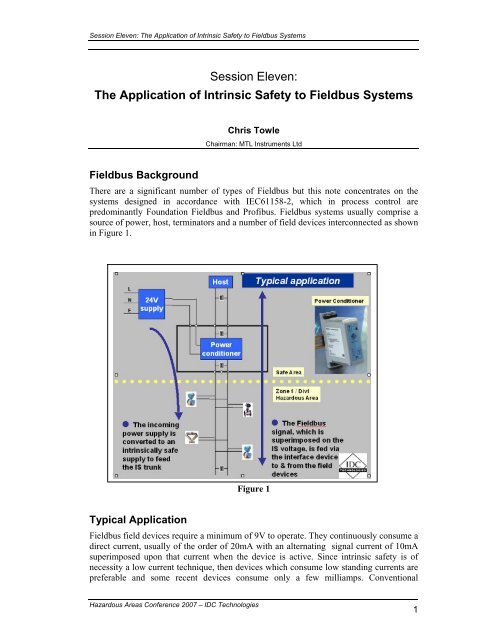
Session Eleven: <strong>The</strong> <strong>Application</strong> <strong>of</strong> <strong>Intrinsic</strong> <strong>Safety</strong> <strong>to</strong> <strong>Fieldbus</strong> <strong>Systems</strong>Session Eleven:<strong>The</strong> <strong>Application</strong> <strong>of</strong> <strong>Intrinsic</strong> <strong>Safety</strong> <strong>to</strong> <strong>Fieldbus</strong> <strong>Systems</strong>Chris TowleChairman: MTL Instruments Ltd<strong>Fieldbus</strong> Background<strong>The</strong>re are a significant number <strong>of</strong> types <strong>of</strong> <strong>Fieldbus</strong> but this note concentrates on thesystems designed in accordance with IEC61158-2, which in process control arepredominantly Foundation <strong>Fieldbus</strong> and Pr<strong>of</strong>ibus. <strong>Fieldbus</strong> systems usually comprise asource <strong>of</strong> power, host, termina<strong>to</strong>rs and a number <strong>of</strong> field devices interconnected as shownin Figure 1.Figure 1Typical <strong>Application</strong><strong>Fieldbus</strong> field devices require a minimum <strong>of</strong> 9V <strong>to</strong> operate. <strong>The</strong>y continuously consume adirect current, usually <strong>of</strong> the order <strong>of</strong> 20mA with an alternating signal current <strong>of</strong> 10mAsuperimposed upon that current when the device is active. Since intrinsic safety is <strong>of</strong>necessity a low current technique, then devices which consume low standing currents arepreferable and some recent devices consume only a few milliamps. ConventionalHazardous Areas Conference 2007 – IDC Technologies1
Session Eleven: <strong>The</strong> <strong>Application</strong> <strong>of</strong> <strong>Intrinsic</strong> <strong>Safety</strong> <strong>to</strong> <strong>Fieldbus</strong> <strong>Systems</strong><strong>Fieldbus</strong> systems are restricted <strong>to</strong> 32 devices per system. However this is very rarelyapproached because <strong>of</strong> the power required, the time it takes <strong>to</strong> address such a system andthe implied system reliability. An average <strong>of</strong> about eight devices is common with twelvedevices being not unusual.Early intrinsically safe <strong>Fieldbus</strong> installations used a resistive limited shunt diode safetybarrier but this restricted the available current and voltage and imposed a safety earth onthe system, which caused some operational difficulties. In addition the safetydocumentation was complex because <strong>of</strong> the number <strong>of</strong> devices in the system. <strong>The</strong><strong>Fieldbus</strong> <strong>Intrinsic</strong>ally Safe Concept [FISCO] was developed <strong>to</strong> alleviate these problems.However there is no reason why the conventional system rules should not be applied <strong>to</strong><strong>Fieldbus</strong> systems if this approach is preferred.FISCO Installation<strong>The</strong> experimental work on which FISCO is based was carried out by PTB [<strong>The</strong> Germancertification organisation] and the initial proposal derived from the report on that workPower-supplies and Power-supply Characteristics: Increased power was made availableby using constant current power supplies instead <strong>of</strong> the usual resistive limited supplies. Ithas been known that additional power could be safely derived by using constant currenttechniques for many years but it is only comparatively recently that semiconduc<strong>to</strong>r serieslimitation has become internationally acceptable. Even now it is regarded with suspicionand only permitted for “ib” [Zone 1] circuits. Almost all existing intrinsically safe systemtheory is based on resistive limited circuits and consequently constant current supplies arenot commonly used except in <strong>Fieldbus</strong> circuits. An annex <strong>of</strong> the system standarddiscusses the techniques for combining constant current and resistive limited sources <strong>of</strong>power and is 74 pages <strong>of</strong> detailed Germanic logic. This is in itself sufficient <strong>to</strong> discouragethe use <strong>of</strong> constant current supplies in non-<strong>Fieldbus</strong> applications. <strong>The</strong> FISCO standarddefines the acceptable voltages and currents and how the power supply can be used inFISCO systems. <strong>The</strong> increase in available current over that from a resistive limited powersource varies with the voltage but at 18V is approximately a fac<strong>to</strong>r <strong>of</strong> two. <strong>The</strong> poweravailable if a IIC [hydrogen] system is required is restrictive, but where a IIB [ethylene]system is acceptable the available current increases by a fac<strong>to</strong>r <strong>of</strong> two and is considerablyless restrictive<strong>The</strong> use <strong>of</strong> “three port” galvanic isolation enables the <strong>Fieldbus</strong> circuits <strong>to</strong> operate asbalanced circuits and removes the difficult problem <strong>of</strong> interacting earth faultsA FISCO power supply when used in the conventional manner illustrated in Figure 1 has<strong>to</strong> deliver direct currents from a low impedance [1Ω] and present a high impedance at thesignal frequencies [100kΩ]. This complicates the power supply and tends <strong>to</strong> interact withthe safety requirements. <strong>The</strong> useable power from an intrinsically safe power supply isalways significantly lower than the safety description because <strong>of</strong> <strong>to</strong>lerances in the safetycomponents and the voltage drop across them. <strong>The</strong> more useable power supplies alsoreshape and boost the received signal.Other Devices: <strong>The</strong> design <strong>of</strong> the remainder <strong>of</strong> <strong>Fieldbus</strong> devices is governed by the need<strong>to</strong> be compatible with the power supply output. In particular they must be IIC certifiedand be capable <strong>of</strong> dealing with the 5,32 w available from the IIB power supply. <strong>The</strong>irpermissible effective input parameters are restricted <strong>to</strong> 5nF and 10μH so that they can beadded <strong>to</strong> a FISCO system without further consideration.Hazardous Areas Conference 2007 – IDC Technologies2
Session Eleven: <strong>The</strong> <strong>Application</strong> <strong>of</strong> <strong>Intrinsic</strong> <strong>Safety</strong> <strong>to</strong> <strong>Fieldbus</strong> <strong>Systems</strong><strong>The</strong> requirements <strong>of</strong> the termina<strong>to</strong>rs are closely and simply defined so that they cannotcause a problem.<strong>The</strong> usual “simple apparatus” requirements apply, with the additional limitation oncapacitance and inductance <strong>to</strong> 5nF and 10μH.System DesignA major difference in the FISCO approach from that <strong>of</strong> conventional systems is thetreatment <strong>of</strong> cable capacitance and inductance. <strong>The</strong> PTB research demonstrated thatunder the permitted voltage and current conditions and provided that the cable parameterswere within certain limits the adding cable tended <strong>to</strong> make the circuit safer. Consequentlythe FISCO standard requires that cables have parameters between the following limits;loop resistance 15 <strong>to</strong> 150 Ω/km, loop inductance 0,4 <strong>to</strong> 1,0 mH/km and capacitance 45 <strong>to</strong>200 nF/km and then no further consideration <strong>of</strong> cable parameters is necessary.Conventional instrument cable is always within these limits and hence the need <strong>to</strong>document cable lengths and calculate capacitance and inductance is removed. <strong>The</strong>re is acable length restriction in IIC systems <strong>to</strong> 1 km but this is because <strong>of</strong> the absence <strong>of</strong>supporting experimental evidence rather than belief that it is unsafe <strong>to</strong> exceed 1km. Inpractice trunk lengths in IIC systems are usually restricted by voltage drop in the cableresistance. IIB systems are permitted a 5km cable length and hence there is no problem ifthe less sensitive gas group is acceptable. [<strong>Fieldbus</strong> trunks are usually limited <strong>to</strong> 1,8 kmfor operational reasons.] <strong>The</strong>re is a restriction on spur lengths <strong>to</strong> 60m because they areunterminated extensions and because <strong>of</strong> restricted experimental evidence. This is notusually a problem but can affect the location <strong>of</strong> junction boxes.When the specified cable and equipment is used a system can be created without furtherconsideration <strong>of</strong> the safety aspects. <strong>The</strong> gas group <strong>of</strong> the system is determined by thepower supply and the temperature classification <strong>of</strong> each apparatus by the certification <strong>of</strong>that apparatus. <strong>The</strong> required documentation is a list <strong>of</strong> the equipment used in the systemand their apparatus certification. <strong>The</strong> format used is not critical.Practical Consideration<strong>The</strong> principal restriction on a FISCO “ib system” is the limitation imposed by thepermitted current and voltage, which restricts the number <strong>of</strong> devices which can beconnected and the length <strong>of</strong> bus which can be utilised. <strong>The</strong> possible interconnections areinfinite and it is difficult <strong>to</strong> choose a truly representative sample.Available power supplies have different combinations <strong>of</strong> voltage and current anddifferent field devices require different continuous levels <strong>of</strong> current. <strong>The</strong> two diagramsillustrate the simple arithmetic necessary <strong>to</strong> ensure operability and assume a trunkresistance <strong>of</strong> 50 Ω/km and a device current consumption <strong>of</strong> 20mA. A more optimisticresult can be achieved by using a thicker cable and reducing the current consumption perdevice but the values used are not unrepresentative.<strong>The</strong> illustrated results <strong>of</strong> five devices on a 600m trunk in IIC and twelve devices on a300m trunk in IIB are not unrepresentative <strong>of</strong> what can be readily achieved. <strong>The</strong> availabletrunk length can be increased by reducing the number <strong>of</strong> devices.Hazardous Areas Conference 2007 – IDC Technologies3
Session Eleven: <strong>The</strong> <strong>Application</strong> <strong>of</strong> <strong>Intrinsic</strong> <strong>Safety</strong> <strong>to</strong> <strong>Fieldbus</strong> <strong>Systems</strong>FNICO and “ic”<strong>The</strong> <strong>Fieldbus</strong> Non Incendive Concept [FNICO] was established as a technique for usingthe FISCO approach in Zone 2 with larger currents. <strong>The</strong> “non incendive” concept or inIEC terms the “energy limited” [nL] concept will be replaced by the “ic” concept infuture standards and the latest FISCO standard which is at the CDV stage carries thisthrough.<strong>The</strong>oretically it could be possible <strong>to</strong> relax the requirements in several sec<strong>to</strong>rs but inpractice the major change is the considerable increase in permissible current caused bythe change in safety fac<strong>to</strong>r from 1,5 <strong>to</strong> unity. Changes in the remainder <strong>of</strong> therequirements were kept <strong>to</strong> a minimum so as <strong>to</strong> maintain a uniform approach <strong>to</strong> systemdesign and utilisation. <strong>The</strong> majority <strong>of</strong> field devices used in “ic” circuits will be certified“ia IIC T4” because the manufacturers find it more economic <strong>to</strong> manufacture a singledevice useable in all circumstances. To the user this has advantages from a sparess<strong>to</strong>ckholding viewpoint. <strong>The</strong> other advantages <strong>of</strong> the “ic” concept discussed in theprevious paper are equally applicable <strong>to</strong> FISCO systems. In particular, temperatureclassification in normal operation makes life simpler.<strong>The</strong> documentation required is just a simple spread sheet list <strong>of</strong> the equipmentFrom a practical viewpoint the increased current makes it possible <strong>to</strong> interconnect moredevices. For example the number <strong>of</strong> 20 mA devices that can be connected in an IICatmosphere is increased from five <strong>to</strong> nine. <strong>The</strong> practical limitation in “ic IIB”circumstances is nearly always the available length <strong>of</strong> trunk and this problem can beovercome by the use <strong>of</strong> a thicker trunk cable.In practice it is almost impossible <strong>to</strong> create a Zone2 IIC location except in a veryconfined space. Where hydrogen is the risk the concentration has <strong>to</strong> be in excess <strong>of</strong> 10%before the ignition energy <strong>of</strong> the mixture exceeds that <strong>of</strong> IIB gases and because <strong>of</strong> theextreme mobility <strong>of</strong> hydrogen this is unlikely. Consequently almost all freely ventilatedZone2 locations could be designated IIB which would make the use <strong>of</strong> “ic IIB” the normand life much easier.<strong>The</strong> Exe and Exi Combination<strong>The</strong> frequently used solution <strong>to</strong> overcoming the trunk length limitation is <strong>to</strong> use anincreased safety [Exe] trunk and then convert <strong>to</strong> intrinsically safe spurs at a field mountedhub. This allows the power supply <strong>to</strong> operate at higher voltages [24V] and higher currents[2A] and consequently longer trunks and more devices become possible. <strong>The</strong>re are anumber <strong>of</strong> variations on this theme so it is difficult <strong>to</strong> generalise but the increased trunklengths necessary on some installations are achievable. Care should be taken <strong>to</strong> questionthe more extreme claims as they frequently require the rewriting <strong>of</strong> Ohm’s law. [2Aflowing in a 1km cable with a resistance <strong>of</strong> 50Ω requires 100V and cannot be derivedfrom a 24Vsupply].<strong>The</strong> alternative solution <strong>to</strong> meeting the requirement for a long trunk length is <strong>to</strong> use aFISCO power supply as a repeater, if necessary mounting the supply in a Zone 2.However this does require a 24V supply <strong>to</strong> be available at the location <strong>of</strong> the repeater.<strong>The</strong> Exe technique is <strong>of</strong> German origin and was devised as a “safe by design” techniquefor high power electrical equipment <strong>to</strong> overcome an aversion <strong>to</strong> the flamepro<strong>of</strong> technique.<strong>The</strong>re are some difficulties <strong>to</strong> applying the technique <strong>to</strong> light current systems but withsome ingenuity this can be done. It helps if you have a tame German technician <strong>to</strong> makeHazardous Areas Conference 2007 – IDC Technologies4
Session Eleven: <strong>The</strong> <strong>Application</strong> <strong>of</strong> <strong>Intrinsic</strong> <strong>Safety</strong> <strong>to</strong> <strong>Fieldbus</strong> <strong>Systems</strong>the ad hoc decisions and maintain the equipment in the pristine conditions necessary <strong>to</strong>ensure its safety. Fortunately the majority <strong>of</strong> the trunks and the converting hubs are inZone 2 locations and hence the risk is reduced <strong>to</strong> an acceptable level.A typical system is as illustrated in Figure 2, and comprises a power supply, an Exetrunk, <strong>Fieldbus</strong> barriers and Exi spurs leading <strong>to</strong> the field devices. <strong>The</strong> <strong>Fieldbus</strong> barrierconverts the Exe power in<strong>to</strong> an isolated Exi signal allowing the usual advantages <strong>of</strong>intrinsic safety [such as ‘live maintenance’] <strong>to</strong> be applied <strong>to</strong> the spurs and <strong>to</strong> parts <strong>of</strong> thebarrier enclosure. <strong>The</strong> barrier enclosure requires careful design and is usually bought aspart <strong>of</strong> the complete system.Figure 2<strong>The</strong> primary advantage <strong>of</strong> the <strong>Fieldbus</strong> barrier is that it allows longer trunks <strong>to</strong> be used.<strong>The</strong> advantage is reduced by the additional voltage drop [16V] required by the barrier andthe additional current used <strong>to</strong> operate the barrier. Nevertheless the advantage gained issignificant. A further advantage is that the power supply can be made redundant. <strong>The</strong>disadvantages are that there is a significant amount <strong>of</strong> complex electronics in the field,the use <strong>of</strong> two explosion protection techniques complicates the installation andmaintenance procedure and it is frequently more expensiveMaintenance and Inspection<strong>Fieldbus</strong> systems [in common with other “smart” equipment] are relatively easy <strong>to</strong>moni<strong>to</strong>r for operational reliability and there are a number <strong>of</strong> modules specificallydesigned for this purpose. A <strong>Fieldbus</strong> system can be continuously moni<strong>to</strong>red <strong>to</strong> check thatit is operating correctly and also by recognising deterioration in signal quality canHazardous Areas Conference 2007 – IDC Technologies5
Session Eleven: <strong>The</strong> <strong>Application</strong> <strong>of</strong> <strong>Intrinsic</strong> <strong>Safety</strong> <strong>to</strong> <strong>Fieldbus</strong> <strong>Systems</strong>anticipate some forms <strong>of</strong> failure. In particular early recognition <strong>of</strong> damage <strong>to</strong> cables is asignificant improvement on conventional techniques.<strong>The</strong>oretically an instrument could operate successfully and have failed <strong>to</strong> a dangerouscondition but this is not likely. <strong>The</strong> safety components in an intrinsically safe apparatushave all been derated and hence any misuse or deterioration with time is more likely <strong>to</strong>preferentially affect operational components. In any case it is <strong>of</strong>ten impossible <strong>to</strong> checkthe integrity <strong>of</strong> safety components, [for example under encapsulation,] hence a frequen<strong>to</strong>perational check is an improvement on the previously accepted norm. If this system is <strong>to</strong>be effective in increasing safety it must be backed up by removing the defective devicewithin a short time. <strong>The</strong> removal <strong>of</strong> defective equipment is part <strong>of</strong> good housekeeping onall plants but is arguably more important in hazardous locations.<strong>The</strong> need for routine inspections and the tedious reading <strong>of</strong> illegible unintelligible labelscan be removed because the moni<strong>to</strong>ring system can detect any changes in the equipmentused in the system. If the initial inspection is thorough it is only changes that can causedanger. An infrequent check on mechanical condition is all that is required <strong>to</strong> supplementwhat is effectively continuous inspection<strong>Intrinsic</strong>ally Safe EthernetA limitation <strong>of</strong> Foundation <strong>Fieldbus</strong> and Pr<strong>of</strong>ibus in some applications is its speed. <strong>The</strong>reis an increased use <strong>of</strong> Ethernet in process control within hazardous areas and there are anumber <strong>of</strong> intrinsically safe devices available <strong>to</strong> facilitate its use. Quite how far and fastits use will grow is open <strong>to</strong> speculation but there are some attractive possibilities whichtake advantage <strong>of</strong> its higher speed and <strong>of</strong> the range <strong>of</strong> components and facilities createdby its wider use. Whether the application <strong>of</strong> Ethernet will develop so as <strong>to</strong> maintain thedesirable ‘open system’ approach will be interesting <strong>to</strong> watch.This note is only intended <strong>to</strong> draw attention <strong>to</strong> the development. <strong>The</strong> subject wouldrequire another paper <strong>to</strong> be adequately considered.Conclusion<strong>The</strong> use <strong>of</strong> <strong>Fieldbus</strong> in hazardous areas is now a mature subject from both a standards andavailable equipment viewpoint. In particular the use <strong>of</strong> “ic IIB” systems in Zone 2locations <strong>of</strong>fers a simple solution <strong>to</strong> a large number <strong>of</strong> problems. In general fulladvantage <strong>of</strong> the ‘smart’ element <strong>of</strong> the available equipment <strong>to</strong> reduce inspection andmaintenance requirements has not been taken at the present time.Longer term it may be that imposing FISCO type limitations on other types <strong>of</strong> apparatusand associated cables could be used <strong>to</strong> create a simpler and safer way <strong>of</strong> creating systems.This would help <strong>to</strong> reduce the common misapprehension that intrinsic safety iscomplicated. It would make the design <strong>of</strong> apparatus more complex but this is done oncein controlled circumstances under ‘certified’ surveillance. In contrast systems are createdunder less well supervised circumstances and hence the rules for combining equipmentshould be kept as simple as possible. However this desirable development is unlikely <strong>to</strong>occur in the foreseeable future.<strong>The</strong> FISCO standard IEC 60079-27 will be replaced by annexes in the apparatus andsystem standards in the next few yearsHazardous Areas Conference 2007 – IDC Technologies6