simrad gd10l - ir gas detector operating manual - ICEWeb
simrad gd10l - ir gas detector operating manual - ICEWeb
simrad gd10l - ir gas detector operating manual - ICEWeb
- No tags were found...

Create successful ePaper yourself
Turn your PDF publications into a flip-book with our unique Google optimized e-Paper software.
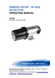
SIMRAD GD10L - IR GAS DETECTOROPERATING MANUALP3382EMay 2002Simrad Optronics ASA – Ensjøveien 23 B – P.O. Box 6114, Etterstad – N0602 OSLO, NORWAYPhone +47 22 66 60 00 – Fax +47 22 66 60 01 <strong>gas</strong>sales@<strong>simrad</strong>-optronics.no - www.<strong>simrad</strong>-optronics.no
1. PRODUCT DESCRIPTION1.1 INTRODUCTIONThe GD10L is an open path <strong>gas</strong> <strong>detector</strong> consisting of a combined transmitter/receiver unit and aseparate reflector.The GD10L is based on the highly acclaimed GD100 and GD10P point <strong>detector</strong>s. Over the past 15years, the GD100 and GD10P have proven themselves to be the most reliable point <strong>detector</strong>s on themarket. Like Simrad's range of point <strong>detector</strong>s, the GD10L has the advantage of using a solid-state,silicon-based IR source that requ<strong>ir</strong>es no recalibration or replacement during its service life. The IRsources have an expected service life of more than 60 years, which keeps maintenance costs to aminimum. The IR sources are resistant to vibration and shock. And,unlike most <strong>detector</strong>s in use today,the GD10L will not cause any false <strong>gas</strong> alarms.1.2 GENERAL DESCRIPTIONThe GD10L fully implements the dual wavelength, dual optical path measuring concept. Radiationfrom the two silicon-based IR sources, which is chopped with a frequency of more than 50 Hz, passesthrough two narrowband optical filters. One wavelength is adapted to the <strong>gas</strong> to be detected while theother wavelength is chosen outside the absorption spectrum of the <strong>gas</strong>The GD10L uses two IR <strong>detector</strong>s. Each <strong>detector</strong> receives radiation signals from both IR sources.Integrated in one unit, the transmitter and receiver are synchronised by the same microprocessor,which means that the synchronous operation of the unit can not be disturbed by IR beam interference.The GD10L is by far the most advanced product on the market, and the only product that has built-insafety against false <strong>gas</strong> alarms caused by external interference or variations in optical and electroniccomponents.The GD10L continuously monitors the measuring path and the optical and electronic functions. The<strong>detector</strong> will always show correct <strong>gas</strong> concentration as long as there are no error messages.The <strong>detector</strong> and reflector optics are heated to keep the optical surfaces free from dew, snow and ice.The heating element in the reflector is self-adjusting. Both the <strong>detector</strong> and reflector have solidweather protectors.The GD10L can easily be installed by one person as only one unit requ<strong>ir</strong>es accurate alignment. The<strong>detector</strong> and reflector brackets have been designed to resist vibration and shock. The reflector shouldbe mounted perpendicular to the measuring path d<strong>ir</strong>ection. Choice of reflector size is dependent onthe length of the measuring path.Maintenance will normally consist in cleaning the <strong>detector</strong> andreflector optics. The <strong>detector</strong> gives an error message if cleaning is requ<strong>ir</strong>ed.1.3 AREAS OF APPLICATIONArea monitoring of:• OIL AND GAS INSTALLATIONS ONSHORE AND OFFSHOREPetrochemical plantsChemical plantsRefineriesPipelinesMarineWaste disposal plantsCar parking buildingsIndustryTHE GD10L OPEN PATH DETECTOR IS NORMALLY RECOMMENDED AS A SUPPLEMENT TOTHE GD10P POINT DETECTOR, OR TO BE USED IN APPLICATIONS WHERE POINT GASDETECTORS ARE UNSUITABLE.2
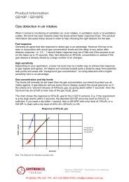
1.4 PRINCIPLE OF MEASUREMENTThe GD10L uses two optical measuring paths, one external path, which measures <strong>gas</strong> concentration,and one internal path that monitor the optical and electronic components. By employing this concept,each <strong>detector</strong> measures both wavelengths. This concept prevents any possible drift caused byalterations in the IR sources, <strong>detector</strong>s and electronics from provoking false <strong>gas</strong> alarms.The transmitter and receiver are integrated in one unit with d<strong>ir</strong>ect synchronisation between transmitterand receiver functions so that false <strong>gas</strong> alarms caused by synchronisation errors are avoided. Thismeasurement concept in combination with Simrad's unique IR sources result in a stable and reliable<strong>detector</strong> without false <strong>gas</strong> alarms or suppression of real <strong>gas</strong> alarms. Through Simrad's point <strong>detector</strong>s,this concept has shown a far better stability and reliability than any other <strong>detector</strong> concept on themarket.Figure 1-1 Transmission as a function of wavelengthOne wavelength, the measuring wavelength, is chosen where the actual <strong>gas</strong> has a specific absorptionline. The other wavelength, the compensation wavelength, is chosen where the <strong>gas</strong> has no absorptionlines and where other <strong>gas</strong>es and atmospheric conditions have no impact on the <strong>gas</strong> measurement. Bycomparing the amplitude of both wavelengths, before and after the IR beam has passed through themeasuring path, the <strong>gas</strong> concentration is determined. Since both wavelengths are monitored by bothIR <strong>detector</strong> elements, alterations in optical or electronic components are unable to cause erroneousmeasurements.Figure 1-2Sequence diagram, synchronismThere is no risk of unreliable measurements caused by synchronisation errors in the receiver unitsince both the pulsing of the IR source and the timing of the IR <strong>detector</strong>s are d<strong>ir</strong>ectly controlled by thesame microprocessor.As in the point <strong>detector</strong> GD10P, the IR sources are silicon-based components with an expected service lifeof more than 60 years. They will not be impa<strong>ir</strong>ed or damaged by mechanical shock or vibration.The measuring concept has been used with great success in all types of <strong>operating</strong> conditions for more3
than 15 years in the point <strong>detector</strong>s GD100 and GD10P.Figure 1-3Measuring concept, block diagram2. INSTALLATION2.1 POSITIONING OF OPEN-PATH DETECTORSThe <strong>gas</strong> concentration of a <strong>gas</strong> cloud is reduced very rapidly as the distance from the source of theleak increases. The <strong>detector</strong> should therefore be placed as close as possible to potential leakagesources. Normally occurring wind d<strong>ir</strong>ections must be taken into account when positioning the <strong>detector</strong>.The <strong>detector</strong> should be placed between potential leakage sources and potential ignition sources.In closed-in or protected areas the positioning of a <strong>detector</strong> should be determined by whether the <strong>gas</strong>is heavier or lighter than a<strong>ir</strong>.2.2 MOUNTING OF THE DETECTOR AND REFLECTORThe reflector bracket (ref. fig. 2-1) is to be fitted perpendicular to the measuring path, within ±5degrees. Both tilt and pan orientation of the panel should be within ±5 degrees.Because of the<strong>ir</strong> long and open measuring path, open-path <strong>detector</strong>s have relatively unprotectedoptics which are much more exposed to external interference than point <strong>detector</strong>s. To achievemaximum <strong>operating</strong> time, the local env<strong>ir</strong>onment and the stability of the structure to which they areattached must be taken into consideration.2.2.1 The following points should be taken into account when positioning open-path <strong>detector</strong>sThe measuring path should be horizontal. This reduces interference from rain, snow and sunlight. The<strong>detector</strong> should be attached to a mechanically stable structure to keep the device stable whensubjected to the prevailing weather conditions and other mechanical loads such as, for example:4
thermal movement due to the effects of the sun and temperature changesthe effects of strong windvibration from equipment such as pumps, turbines and cranes, high-pressure flushing of the <strong>detector</strong>etc.The <strong>detector</strong> can be brought out of alignment by being knocked or as a result of some othermechanical effects, particularly if the <strong>detector</strong> is located in high-traffic areas.UNDER THE ABOVE CONDITIONS, THE FOLLOWING REMEDIAL ACTIONS ARE RECOMMENDED:The reflector should be attached to the structure which has the heaviest exposure to mechanicalinterference.Use the large reflector (30x30)Do not use long measuring paths.The <strong>detector</strong> should be positioned in such a way that the measuring path does not cross the hightrafficareas and movable machinery cannot block the measuring path. Other factors to be taken intoaccount could be temporary scaffolding, large vehicles etc.The <strong>detector</strong> should be positioned in such a way that exhaust or steam discharges do not d<strong>ir</strong>ectly hitthe optics.In places where there can be thick fog or heavy snowdrifts the measuring path should be made asshort as possible.Figure 2-1 Brackets with dimensions of mounting holes (20x20 bracket in parenthesis)5
2.3 ELECTRICAL CONNECTIONSDetector, termination dep. Junction box System1 +24 V 1 +24 V +24 V2 24 V return 2 24 V return 24 V return3 4-20 mA output 3 4-20 mA output 4-20 mA input4 +RS 485 4 +RS485 Not used5 -RS 485 5 -RS 485 Not used6 Not used Not used- Shield 0 Shield ShieldFigure 2-2Electrical connectionsElectrical connections forreflector junction box:Junction box1 220/110 V AC2 220/110 V AC3 Shield4 Not used3. COMMISSIONING3.1 PREPARATIONCheck that the reflector is mounted perpendicular to the measuring path d<strong>ir</strong>ection, within ±5 degrees.Both tilt and pan orientation of the panel must be within ±5 degrees. Commissioning should be carriedout in clear weather in order to be able to calculate the transmission of the measuring path correctly,and to achieve the best possible accuracy of the zero-point calculation.Check that there is a free line of sight between the <strong>detector</strong> and the reflector.Check that optical surfaces on the <strong>detector</strong> and reflector are clean and dry.Check that there are no HC <strong>gas</strong>es present during commissioning.Carry out rough setting using the adjusting sight.6
3.2 COARSE ALIGNMENT USING THE ADJUSTMENT SIGHTFit the adjusting sight to the <strong>detector</strong>’s weather protector using the rubber belt provided.Figure 3-1 Adjusting sightFor simplest adjustment it is advantageous for the sight to be placed right on top of the weatherprotector, or in the middle of the side of the <strong>detector</strong>. The sight is used in the same way as pistolsights. There should be a distance of about 50 cm between the eye and the sight. Correct alignment ofthe sensor is obtained when both alignment rings and the centre of the reflector panel are aligned.Figure 3-2Adjustable holder for <strong>detector</strong>3.2.1 ProcedureNote:Screws H, I and J are not to be moved. These have already been adjusted at the factory.Set adjusting screw A in the centre of the adjusting range and check that locking screw B is notrestricting the adjusting range.Check that locking screws C and D have been loosened so that the <strong>detector</strong> can be moved freely inthe horizontal plane.Align the <strong>detector</strong> in the horizontal plane.7
Adjust the <strong>detector</strong> in the vertical plane using adjusting screw E. Check that locking screws F and Gare not restricting movement.Tighten locking screws C and D with a torque of about 5 Nm.Re-adjust the <strong>detector</strong> using adjusting screws A and E so that the reflector is in the centre of the lineof sight of the adjusting sight.3.3 FINE-TUNING AND ZERO ADJUSTMENT USING THE HAND TERMINALThe sight can now be removed from the <strong>detector</strong>.Note:The <strong>detector</strong>’s measuring path must not be blocked during this part of the procedure.3.3.1 ProcedureConnect the hand terminal to the terminal block in the junction box.The display will show the following text:S I M R A D O P T R O N I C ST e r m i n a l f o r G D 1 0 LV e r s x xM E N U ↵Press ENTER, ↵, on the terminal.The terminal displays the following text:C o m m u n i c a t i o n t e s tP l e a s e w a i tA d d r e s s n o x xWhen the terminal has identified the <strong>detector</strong>, the following text is displayed:↑S e n s o r i n s t a l l a t i o n↓S E L E C T F U N C T I O N ↵Select “ Detector installation” by pressing ENTER. If necessary, use the arrow keys to find thisfunction. The following text is displayed:A d j u s t a l i g n m e n t t om a x . s i g n a l a n dg r a p h l e v e lL o c k a d j s c r e w s ↵Press ENTER on the terminal. The following text is displayed:S i g n a l l e v e l x x- - - - - - - - - -8
A L I G N F I N I S H E D ? ↵“Signal level” is a measure of the magnitude of the returned IR signal with coarse resolution.”- - - - - - - - - -” is an expanded bar diagram of “Signal level” with high resolution.Fine-tune the <strong>detector</strong> by adjusting the screws A and E so that the numerical values of “Signal level”and the bar diagram are as high as possible. Point the <strong>detector</strong>’s IR beam as close as possible to thecentre of the reflector. This is done by setting the adjusting screws in the middle of the adjustinginterval where the magnitude of “Signal level” is constant.Tighten locking screw B with a torque of 3 Nm. Tighten the locking nuts for screws A and B while thescrews are held in position. Check that the signal level has not changed.Screw the locking screws F and G in by hand until they abut the baseplate of the holder, check thatboth screws are resting against the baseplate.Then tighten the locking nuts for each screw while the screw is held in position. Check that the signallevel has not changed. If necessary, re-adjust the <strong>detector</strong> with adjusting screw E.Then tighten the locking nut for screw E while the screw is held in position.Press ENTER on the terminal. The following text is displayed:P e r f o r m i n g a n a l o gs i g n a l c a l i b r a t i o nP l e a s e w a i tThe <strong>detector</strong> calculates analog parameters and stores them. When these calculations have beencompleted (30 – 40 sec.), the following text is displayed:P a t h g a i n x x xM e a s g a i n x x xC o m p g a i n x x xS T A R T Z E R O C A L I B R ↵Then press ENTER to start zero adjustment (approx. 3 min. duration) of the <strong>detector</strong>. While zeroadjustment of the <strong>detector</strong> is in progress, the following text is displayed:C a l c u l a t i n g z e r oP l e a s e w a i ta p p . 3 m i nx x xwhere X.XX is a clock that counts minutes and seconds.9
After zero calibration is completed, the following text is displayed:S e n s o r i n s t a l l a t i o nc o m p l e t e dD I S P L A Y G A S V A L U E ↵After zero adjustment is completed, the <strong>detector</strong> automatically goes over to normal <strong>gas</strong> measuringmode.Press ENTER to see the <strong>gas</strong> value as well as transmission along the measuring path. The followingtext is displayed:P a t h t r a n s m . X X X %G a s v a l u e X X % F SM E N U ↵Verify successful installation by checking that path transmission is approx. 100 % and that <strong>gas</strong> value is0 % FS.3.4 FUNCTION TESTSystem and <strong>detector</strong> function test can be carried out using the Simrad Gas Test Filter. Proceed asfollows:• Hold the Gas Test Filter in the measuring path between the <strong>detector</strong> and the reflector for aminimum of 10 seconds. Preferably, hold the filter in front of the <strong>detector</strong> lens so that the plasticaperture covers the whole IR beam diameter.Read <strong>gas</strong> value at the terminal by choosing Display Gas Value in the menu. Refer to para. 5.4.2.Verify that reading approximately matches value printed on the rim of the Simrad Gas Test Filter.Or alternatively, read the <strong>gas</strong> value on the main control system.4. MAINTENANCE4.1 REGULAR MAINTENANCEThe <strong>detector</strong> does not have any internal functions that requ<strong>ir</strong>e regular monitoring or maintenance. Ifthere is d<strong>ir</strong>t on the <strong>detector</strong> lens or reflector window, they can be cleaned with mild soapy water or amixture of isopropanol and water. Use a soft cloth. Before cleaning, the <strong>detector</strong> should bedisconnected from the alarm system.4.2 TROUBLESHOOTINGThe <strong>detector</strong> can give fault messages in the event of weather conditions which to a considerableextent reduce or interfere with the transmission along the <strong>detector</strong>’s measuring path or optics, or whenobjects block the <strong>detector</strong>’s measuring path.The <strong>detector</strong> can also give fault messages if the mounting brackets are not sufficiently stable over timeor in the event of mechanical changes which may, for example, be caused by temperature changes ormovement in the mounting structure. The above-mentioned conditions should be checked beforetroubleshooting is commenced.Troubleshooting should always start by inspecting the <strong>detector</strong>’s lens and reflector surface forcontamination and defects. The following list may be helpful if problems arise:10
Fault message Problem CorrectionCLEAN OPTICSD<strong>ir</strong>t on lens/reflector.Clean optics. If necessary, re-adjust <strong>detector</strong>using terminal.Detector out of alignment. Realign <strong>detector</strong> using terminal.Blocked optics/<strong>detector</strong>failureD<strong>ir</strong>t on lens/reflector. Clean optics. If necessary, re-adjust <strong>detector</strong>using terminal.Detector out of alignment. Straighten <strong>detector</strong> using terminal.Remove objects that block.Objects that block themeasuring path.As a general rule if problems arise, inspect and clean both <strong>detector</strong> and reflector optics. If this doesnot help, realign the <strong>detector</strong> according to procedure (ref. Chapter 3).5. TERMINAL5.1 INTRODUCTIONFigure 5-1 Connection of hand terminal with cable and plugThe terminal is used when setting, zero-adjusting and testing the <strong>detector</strong>.The terminal communicates via a two-way RS 485 communication.The terminal does not have any batteries that need to be changed, and the terminal is powered fromthe <strong>detector</strong> when it is connected.5.2 DESCRIPTION OF TERMINALThe terminal has a 4-line, 20-character backlit display, as well as 4 keys for navigating in menus andfor operator output.The terminal is connected to the <strong>detector</strong> via a plug, which fits into the terminal block in the <strong>detector</strong>’sjunction box.THE KEYS UP AND DOWN SCROLL THROUGH MENUSThe key ENTER Acceptance of a particular function or menuselectionThe key ESCAPE Discontinuation of menu selection in progress11
5.3 START-UPWhen the voltage is connected, the following start-up display appears:S I M R A D O P T R O N I C ST e r m i n a l f o r G D 1 0 LV e r s x xM E N U↵The menu is shown when ENTER is pressed.The UP/DOWN keys are used to navigate in the menu.Before the menu is displayed, the terminal checks the communication with the <strong>detector</strong>, with the following text beingshown:C o m m u n i c a t i o n t e s tP l e a s ew a i tA D D R E S S N O X X ↵If however the terminal is not able to establish communication with the <strong>detector</strong>, the following text isdisplayed:C o m m u n i c a t i o n f a u l tR E S T A R T↵When ENTER is pressed, the terminal makes a new attempt to establish communication with the<strong>detector</strong>.The following functions can be selected from the menu list:-Detector installation-Display <strong>gas</strong> value-Fault messages5.4 FUNCTIONS5.4.1 Installation of <strong>detector</strong>This function is described in chapter 3.3: Fine-tuning and zero adjustment by terminal.5.4.2 Display <strong>gas</strong> valueThis function continuously reads the <strong>detector</strong>’s <strong>gas</strong> value as well as optical transmission along themeasuring path. The following text is displayed:P a t h t r a n s m . X X X %G a s v a l u e X X %M E N U↵where “Path transm.” is the transmission in % along the <strong>detector</strong>’s measuring path.”Gas value” is the <strong>gas</strong> reading as a % of the full scale value.12
If the <strong>detector</strong> is not able to measure <strong>gas</strong>, the value of ”Gas value” is replaced by ”-”.The terminal goes back to the menu when ENTER is pressed.5.4.3 Fault messagesThis function continuously displays any fault messages from the <strong>detector</strong>.The following text is displayed:E r r o rM E N U↑m e s s a g e↓↵The arrows in the display indicate that there are multiple error messages. The hidden error messages are accessed bypressing the UP/DOWN key.The terminal returns to the menu when ENTER is pressed.6. TECHNICAL DATA6.1 DETECTORDetector typeIR sourceGases detectedMeasuring rangeResponse timeDeviationRepeatabilityTemperature rangeHumidityOutput signal:- standard- optionFault messages:Clean opticsThe <strong>detector</strong> fully implements the measuring concept of doublewavelength, double optical path.Silicon based. Operating life more than 60 years. Resistant to shock andvibration.Hydrocarbons0 - 5 LELm calibrated for methane. Option: other <strong>gas</strong>esT50 = 2.5 sec.T90 = 6 sec.±0.2 LELm±0.1 LELm-30 to +45 degrees centigrade0–99 % relative humidity, non-condensating4–20 mA source, maximum total load impedance = 500 ohm.4–20 mA sinkOutput is 1 mA.Beam block/DetectorfailureOutput is 0 mA15 sec. delay on beam block signalPower supply24 V nominal, range: 18–32 VPower consumption 5 WMaterial316, acid-proof stainless steelWeight3.5 kgExplosion proof class. EEx de IIC T6Ingress protection IP 66/6713
6.2 ADJUSTABLE BRACKET FOR DETECTORMaterial316, acid-proof stainless steelWeightDimensions5.5 kg200 x 220 x 220 mm6.3 REFLECTOR 20X20 CMMountingThe reflector is to be mounted perpendicular to the measuring pathd<strong>ir</strong>ection within ±5 degrees.Recommended path 2–20 metreslengthPower supply220 V AC (option 110 V AC)Power consumption Max. 60 W at power-up/15 W normal operationEx classificationEx e (when using heater cable)Material316, acid-proof stainless steelWeight8.5 kgDimensions262.5 x 315 x 327.5 mm6.4 REFLECTOR 30X30 CMMountingThe reflector is to be mounted perpendicularly to the measuring pathd<strong>ir</strong>ection within ±5 degrees.Recommended path 2–30 metreslengthPower supply220 V AC (option 110 V AC)Power consumption Max. 60 W at power-up/15 W normal operationEx classificationEx e (when using heater cable)Material316, acid-proof stainless steelWeight14 kgDimensions308 x 415 x 427.5 mm6.5 TECHNICAL DATA, ACCESSORIES6.5.1 Gas filterDimension of external 16.5 cmdiameterDimension of aperture 12 cmGas responseApprox. 2.4 LELm on standard <strong>detector</strong>6.5.2 Adjusting sightDimensions 15 x 6 x 3.5 cmWeight 180 gMaterial anodised aluminium6.5.3 Hand terminalDimensions 10 x 18 x 4 cmWeight450 gPower supply 24 V nominal, range 18–32 VCurrent0.7 WconsumptionCommunication RS485Ex classNone. Internal voltages only when connected to junction box14
6.6 CERTIFICATIONSGD10L is certified in accordance with the requ<strong>ir</strong>ements that are stated in "Electrical apparatus forexplosive atmospheres" formulated in the following standards from CENELEC:EN 50014 (1997) Electrical apparatus for potentially explosive atmospheres. General requ<strong>ir</strong>ementsAmendment A1 (1999)Amendment A2 (1999)EN 50018 (1994)enclosure “d”EN 50019 (1994)“e”Electrical apparatus for potentially explosive atmospheres. Flame-proofElectrical apparatus for potentially explosive atmospheres. Increased safetyEN 50081-1 (1992) Electromagnetic compatibility - Generic emission standard. Part 1:Residential, commercial and light industryEN 50082-2 (1997 )env<strong>ir</strong>onmentElectromagnetic compatibility - Generic immunity standard. Part 2: IndustrialIEC 529 Classification of degrees of protection, F<strong>ir</strong>st Edition 1996Amendment no. 1 (1978)6.7 CERTIFICATESCertificate of Conformity: NEMKO No. 00 ATEX138 Xin accordance with ATEX D<strong>ir</strong>ective 94/9/EC15
7. ORDERING INFORMATIONDescriptionOrder no.Gas Detector GD10L sourceGas Detector GD10L sink128-811960.4128-813232.6Reflector 20x20 Assy 220 V ACREFLECTOR 20X20 ASSY 110 V ACReflector 30x30 Assy 220 V ACReflector 30x30 Assy 110 V AC499-812837.3499-813540.2499-813022.1499-813541.0Mounting Bracket Assy 499-812468.7Junction Box Assy 108-904807.6Hand Held Terminal Assy 109-813103.9Tool Alignment Assy 708-812800.1Filter Gas Test Assy No 1Filter Gas Test Assy No 2419-813183.1419-813663.216
NOTES:17
NOTES:18