SIMRAD GD10P - IR GAS DETECTOR - ICEWeb
SIMRAD GD10P - IR GAS DETECTOR - ICEWeb
SIMRAD GD10P - IR GAS DETECTOR - ICEWeb
- No tags were found...

You also want an ePaper? Increase the reach of your titles
YUMPU automatically turns print PDFs into web optimized ePapers that Google loves.
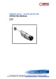
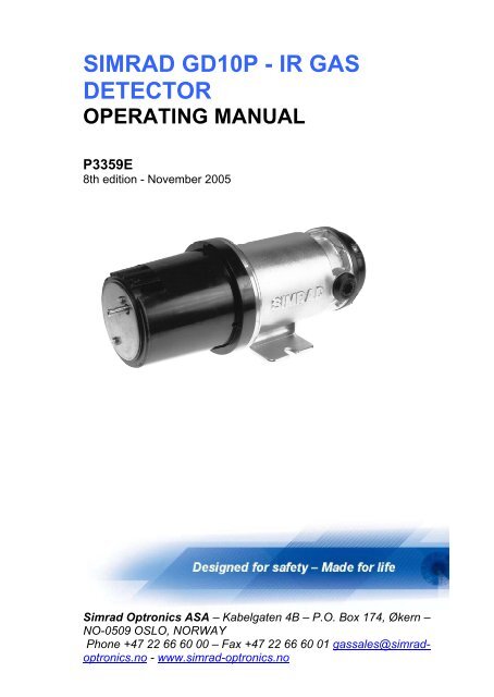
<strong>SIMRAD</strong> <strong>GD10P</strong> - <strong>IR</strong> <strong>GAS</strong><strong>DETECTOR</strong>OPERATING MANUALP3359E8th edition - November 2005Simrad Optronics ASA – Kabelgaten 4B – P.O. Box 174, Økern –NO-0509 OSLO, NORWAYPhone +47 22 66 60 00 – Fax +47 22 66 60 01 gassales@simradoptronics.no- www.simrad-optronics.no
TABLE OF CONTENTS1. PRODUCT DESCRIPTION................................................................31.1 GENERAL DESCRIPTION ...................................................................31.2 CONSTRUCTION ...............................................................................41.3 APPLICATION AREAS........................................................................41.4 TECHNICAL DATA (0-100% LEL METHANE, 5 SEC. RESPONSE TIME)51.5 CERTIFICATION AND STANDARDS....................................................71.6 CERTIFICATES..................................................................................81.7 PRODUCT IDENTIFICATION LABEL....................................................82. INSTALLATION..................................................................................92.1 MOUNTING THE <strong>GD10P</strong>...................................................................92.1.1 Location ..................................................................................92.1.2 Ventilation duct or pipe mounting ..........................................92.1.3 Orientation............................................................................112.1.4 Mounting the <strong>GD10P</strong>............................................................122.2 ELECTRICAL CONNECTIONS ...........................................................122.2.1 Terminal compartment..........................................................122.2.2 Output cable connections .....................................................132.2.2.1 3-wire output cable connection.........................................132.2.2.2 Retrofit mounting..............................................................142.2.2.3 Retrofit wiring ..................................................................142.2.2.4 Recommended cable types................................................142.2.2.5 Initial wiring checks..........................................................153. OPERATION......................................................................................163.1 START-UP PROCEDURE...................................................................164. MAINTENANCE................................................................................174.1 GENERAL.......................................................................................174.2 CLEANING OF OPTICAL WINDOW AND M<strong>IR</strong>ROR...............................174.3 FUNCTION TEST .............................................................................174.4 CALIBRATION TEST........................................................................184.5 FAILURE INDICATIONS ...................................................................195. TECHNICAL DESCRIPTION .........................................................215.1 INTRODUCTION..............................................................................215.2 THE <strong>GD10P</strong> CONCEPT ...................................................................215.3 PERFORMANCE CHARACTERISTICS.................................................235.3.1 Gas data................................................................................235.3.2 Cross interference to other gases .........................................24
5.4 <strong>GAS</strong> DETECTION SYSTEM............................................................... 246. ORDERING INFORMATION......................................................... 256.1 SPARE PARTS LIST........................................................................ 26TABLE OF FIGURESFIGURE 1.1 <strong>GD10P</strong>, OUTLINE DIMENSIONS (MM)........................................ 7FIGURE 1.2 IDENTIFICATION LABEL ............................................................ 8FIGURE 2.1 VENTILATION DUCT OR PIPE MOUNTING USING DUCT MOUNTINGFLANGE KIT REFER TO: FIGURE 2.2 FOR DETAILS. ................. 10FIGURE 2.2 EXPLODED VIEW, DUCT MOUNT FLANGE KIT........................ 11FIGURE 2.3 ORIENTATION OF <strong>GD10P</strong> WEATHER HOUSING IN RELATION TOFLOW D<strong>IR</strong>ECTION.................................................................... 11FIGURE 2.4 <strong>GD10P</strong> MOUNTED BY MEANS OF MOUNTING FEET.................. 12FIGURE 2.5 TERMINAL COMPARTMENT..................................................... 13FIGURE 2.6 BRIDGE INTERFACE INSTALLATION ........................................ 14FIGURE 3.1 SIGNAL OUTPUT DURING START-UP PERIOD............................ 16FIGURE 4.1 SET-UP OF FUNCTION TEST ..................................................... 18FIGURE 4.2 SET-UP OF CALIBRATION TEST................................................ 19FIGURE 4.3 TEST PROCEDURE ................................................................... 20FIGURE 5.1 TRANSMITTANCE AS A FUNCTION OF WAVELENGTH ............... 21FIGURE 5.2 BLOCK DIAGRAM, <strong>GD10P</strong>...................................................... 23
31. PRODUCT DESCRIPTION1.1 General descriptionThe Simrad <strong>GD10P</strong> Gas Detector is a point detector for gasconcentration monitoring in potentially hazardous and/or poisonousenvironments. The <strong>GD10P</strong> is based on infrared absorption and usesthe latest developments in analogue and microprocessor technology.Solid state design improves reliability, long-term stability and accuracyin continuous measurement of gas concentration in ambient air.Compared with catalytic sensors, the <strong>GD10P</strong> has the followingadvantages:Presence of oxygen is not required for correct measurement, whichmakes the <strong>GD10P</strong> suitable even in an inert gas atmosphere.No possibility of poisoning of the detector since no chemical reactionoccurs, i.e. silicon vapours and H 2 S have no effect on the detector orthe measurement.The gas flow rate has no influence on accuracy.There are no saturation effects which could lead to falsemeasurements. Thus, the detector is capable of measuring gasconcentrations up to 100% vol.The detector has a continuous self-test function, and reports dirtyoptics and fault conditions to the control system.Total system costs can be dramatically reduced with the <strong>GD10P</strong>:High reliability results in low test frequency and no calibration costs.Voting systems designed to reduce false alarms are not required,which reduces the number of detectors by up to 66 %.
41.2 ConstructionA complete <strong>GD10P</strong> Gas Detector consists of the following:An external gas measuring path where gas is measured by monitoringabsorption of <strong>IR</strong> radiation. A weather protection enclosure is mountedaround the measuring path to protect the optical surfaces from rainand dust and other contaminants.An optoelectronic unit, which generates <strong>IR</strong> radiation to the gasmeasuring path, measures the reflected <strong>IR</strong> radiation from the gasmeasuring path and calculates the gas concentration. This unit isenclosed by an EExd certified housing.A terminal compartment with cable entry and mini-terminals forelectrical connection. The compartment is protected by a cover and isEExe certified.1.3 Application areasThe <strong>GD10P</strong> is primarily designed for detection of hydrocarbon or CO 2gases in hazardous areas on offshore platforms and petrochemicalplants, but it can also be used in a variety of other applications.For retrofit applications, a bridge interface is available allowing thedetector to be connected directly to catalytic systems, using theexisting cabling and control modules.With the Sample Flow Housing mounted, the detector can be used inaspirator systems or process monitor and control systems.The <strong>GD10P</strong> is housed in a compact stainless steel enclosure, which iscertified flame-proof, meeting the requirements of EN 50018.
51.4 Technical data (0-100% LEL methane, 5 sec.response time)Specification for other types on requestDetection range, standard 0-100% LEL (0-5% Vol.) methane- Option 0-100% Vol. methane- Option Other gases on requestLong-term stabilityBetter than ±5% of full scale readingAccuracy, standard 5 sec. Better than ±3% of full scale between0-50 % readingBetter than ±5% of full scale between50-100 % readingResponse time, standard 5 sec. T20 = 1 sec.T50 = 2.5 sec.T90 = 6 sec.Response time, option 1 sec. T20 = 0.3 sec.T50 = 0.7 sec.T90 = 1.6 sec.Start-up time
6- Electrical connection 3 wires (M20 EExe cable gland)Temperature range:- Storage -40°C to +70°C- Operating -20°C to +45°C- Operating (option) -40°C to +60°C- Humidity (operation) 99% RH non-condensingExplosion-proof housing:- Main compartment EExd IIC T6- Terminal compartment EExeProtection category IP66/IP67 DIN 40050Housing material Stainless steel SIS2343 (ASTM 316)Weight, incl. Weather Approx. 2.9 kgProtectionAccessoriesWeather ProtectionSample Flow HousingDuct Mounting Brackets
7Figure 1.1<strong>GD10P</strong>, outline dimensions (mm)1.5 Certification and StandardsThe <strong>GD10P</strong> has been certified according to:Atex Directive 94/9/EC, EMC Directive 89/336/EEC Article 4 andrequirements laid down by the following standards:EN50014/IEC 60079-0EN 50018/IEC 60079-1EN 50019/IEC 60079-7EN 50054EN 50057EN 61779-1/IEC 61779-1Electrical apparatus for potentiallyexplosive atmospheres.Generalrequirements.Electrical apparatus for potentiallyexplosive atmospheres. Flame-proofenclosure “d”.Electrical apparatus for potentiallyexplosive atmospheres. Increased safety“e”.Electrical apparatus for the detection andmeasurement of combustible gases.General requirements and test methods.Performance requirements for Group IIapparatus indicating up to 100 % lowerexplosive limit.Electrical apparatus for the detection and
8EN 61779-4/IEC 61779-4EN 50081-1EN 50082-21.6 Certificates• Atex Certificate: Nemko 01 ATEX 282• SIMTARS, Australia• ABS• UL1.7 Product identification labelmeasurement of flammable gases. Part 1:General requirements and test methods.Electrical apparatus for the detection andmeasurement of flammable gases. Part 4:Performance requirements for Group IIapparatus indicating a volume fraction upto 100 % lower explosive limit.Electromagnetic compatibility – Genericemission standard. Part 1: Residential,commercial and light industry.Electromagnetic compatibility – Genericimmunity standard. Part 2: Industrialenvironment.The <strong>GD10P</strong> identification label is shown in the figure below. Thecomposition of the label is in accordance with Atex Directive 94/9/EC.Figure 1.2Identification label
92. INSTALLATION2.1 Mounting the <strong>GD10P</strong>2.1.1 LocationThe detector must be mounted horizontally wired according to fig. 2.5.NOTE: The area in which the detector may be mounted must be inaccordance with the certification of the detector and in accordancewith the standards of the appropriate authority in the countryconcerned.Choice of mounting area:• The detector should be mounted where gas leakage is mostlikely to occur. To detect methane, which is lighter than air,inside an enclosed area the detector should be mounted highin the area to be protected or immediately above potentialleakage sites.• To detect gases heavier than air, e.g. propane, the detectorshould be mounted below the potential leakage site.• The detector should be mounted in a place wheremaintenance, i.e. cleaning of the optics, is easily performed.• The detector may be mounted in areas where no oxygen ispresent.• The detector may be mounted in areas with strong airflow• The detector should NOT be mounted where it could beexposed to water drenching.NOTE: The detector must always be used with the Weather Protectionor Sample Flow Housing mounted. Exception to this must bediscussed with Simrad Optronics.2.1.2 Ventilation duct or pipe mountingIf installed in a ventilation duct or pipe, the mounting arrangement andaccessories shown in Figure 2.1 and 2.2 should be used.The Duct Mounting Bracket shown in Fig. 2.2 allows the <strong>GD10P</strong> to bepositioned in the core of the airflow in wide ducts or pipes.NOTE: Avoid direct light on lens and mirror if the <strong>GD10P</strong> is mountedwithout the Weather Protection.
10In order to achieve minimum response time, the Weather Protectionmust be oriented with the flow direction indicator facing into the airflow. See procedure in section 2.1.3.The sensor must be mounted in straight parts of the duct withundisturbed airflow. Avoid areas with possible turbulent flow e.g.immediately after sharp bends or junctions.Figure 2.1Ventilation duct or pipe mounting using Duct MountingFlange KitRefer to: Figure 2.2 for details.
11Figure 2.2Exploded view, Duct Mount Flange Kit2.1.3 OrientationThe detector should be mounted so that the longitudinal axis of thedetector is horizontal. This will prevent accumulation of water and duston the optics. The Weather Protection must always be orientedcorrectly for optimal performance.NOTE: When the <strong>GD10P</strong> is mounted outdoors, the flow directionindicator must point upwards.See “Flow Direction Indicator” in Fig. 2.3 below. Orientation of theWeather Protection is performed as follows:• Use a screwdriver to loosen the two screws on the WeatherProtection• Rotate the Weather Protection to correct position• Tighten the screw with a torque of max. 0.5 NmFlow directionindicatorFlowdirectionFigure 2.3Orientation of <strong>GD10P</strong> weather housing in relation toflow direction
122.1.4 Mounting the <strong>GD10P</strong>The detector is mounted by means of a projecting mounting leg usingtwo M8 screws and washers, or by means of the Duct MountingFlange Kit (4 x M8 screws).Weather ProtectionM8 screwFigure 2.4<strong>GD10P</strong> mounted by means of mounting feet2.2 Electrical connections2.2.1 Terminal compartmentThe terminal compartment is accessible by removing the circularterminal cover. (Loosen the four M5 screws.) Refer to Figure 2.5.The terminal compartment, including the 5 mini-terminals for electricalconnection, is shown in Figure 2.5.The installation wiring enters the terminal compartment via a singleM20 EExe cable gland, which can be mounted on either side of thecompartment. The unused entry is blanked with an EExe cover.
13Local earth fixingFigure 2.5Terminal compartmentTerminal 1 +24 VDCTerminal 2 24 V return (0 V)Terminal 3 4-20 mA output2.2.2 Output cable connectionsThe detector has two output modes:Terminal 4 Factory use onlyTerminal 5 Factory use only- Current source 4-20 mA (standard)- Current sink 4 - 20 mA (option)The mode is factory set, and shown on the identification plate of thedetector.2.2.2.1 3-wire output cable connectionThe cable connections are as follows:Terminal No l: +24V DCTerminal No 2: 0 V DC (24 V and signal return)Terminal No 3: Signal outputThe shield of the cable should be connected to instrument earth in thecentral control module, and left unterminated at the detector. Do notconnect clean earth conductors to the local earthing screw.
142.2.2.2 Retrofit mountingFor retrofit of catalytic sensors an adapter plate is available allowingthe <strong>GD10P</strong> to be mounted using the same hole pattern as mostcatalytic sensor junction boxes. Refer to section 6.0.2.2.2.3 Retrofit wiringThe <strong>GD10P</strong> Gas Detector has been designed to be fullyinterchangeable with existing catalytic sensors, using the same 3-wirecable and the same bridge input control modules. This applicationrequires the Bridge Interface to be employed as shown in Figure 2.6below.The Bridge Interface (Simrad reg. no. 109-804511.4) converts thestandard 4 - 20 mA active current output from the <strong>GD10P</strong> to a bridgesignal input, which is a typical standard for several control modules inuse today. The Bridge Interface operates on a standard 24V DCsupply. The complete Bridge Interface assembly is contained in aplastic housing, which clips onto a standard DIN mounting rail. Thisallows several channels to be interfaced in a space-saving way.NOTE: As signal levels, polarity, loading, stability and fault testingdiffer between manufacturers of catalytic modules, Simrad Optronicsmust be contacted for correct setting of variables in the BridgeInterface.Figure 2.6Bridge interface installation2.2.2.4 Recommended cable typesThe cable selected for interfacing the control equipment should beapproved for use in the actual area.
15It is recommended to use shielded cables.Cables should be of a fine multi-strand type with a cross-sectionbetween 0.5 mm 2 and 1.5 mm 2 .The cable enters the terminal compartment via an EExe cable gland.Several options of gland fittings are available.2.2.2.5 Initial wiring checksAfter wiring as detailed above, and before applying power, ensure that:• +24V DC is connected to terminal l• 0 V DC is connected to terminal 2• Signal output is connected to terminal 3
163. OPERATION3.1 Start-up procedureEnsure that system wiring and control system are in working orderbefore switching on power to the detector.The detector will then perform self-test and internal signal adjustmentslasting for approx. 60 seconds and switch to measuring mode.The output signal from the detector during this period is shown inFigure 3.1 below (current output of the <strong>GD10P</strong> standard version).Signal output before 60 seconds is 0 mA, and signal output after 60seconds is 4 mA (if no gas is present).Figure 3.1Signal output during start-up period
174. MAINTENANCENOTE: The <strong>GD10P</strong> has no user adjustable parts. It is notrecommended to open the <strong>GD10P</strong>, as this will change the internalatmosphere, and the initial calibration could be affected.NOTE: Opening the <strong>GD10P</strong> voids all warrantee offered at time of sale.4.1 GeneralThe <strong>GD10P</strong> has been designed to require a minimum of maintenance.The only necessary maintenance is to inspect visually that theWeather Protection is not clogged in heavily contaminated areas.4.2 Cleaning of optical window and mirrorIf the optical window and mirror have to be cleaned, use a soft, cleantissue to rub off the contamination. The window and mirror are madeof sapphire, which is highly resistant to scratching. Make sure that thewhole optical surface is clean.NOTE: For difficult contaminants the mirror and lens can be cleanedwith an equal-part mixture of isopropyl alcohol and water. Do notperform any testing of the sensor before this solution has dried andresidues have been wiped away4.3 Function testIn order to perform function test of the detector, a test gas can beapplied through a 6 mm test nozzle on the front of the WeatherProtection housing. Read the effect on the sensor output signal orthrough the gas detection system.The <strong>GD10P</strong> has been designed for long-term stability, and in order toretain the high reliability of the <strong>GD10P</strong> it is only necessary to monitorthe detector's zero point and error messages from the detector. Toavoid inhibiting the response time of the detector, the WeatherProtection has been designed as open as possible to facilitate gasflow-through. Therefore, it is difficult to fill the gas measuring pathcompletely with test gas, especially in windy weather.A function test of the <strong>GD10P</strong> can be performed as follows:• If there is no air movement, a test gas flow of minimum 4litres/minute will give approximately the same value as the testgas.
18• If there is an air movement of 0.5 m/sec., the test gas flowmust be increased to 20 litres/minute to show the same value.• At high air velocities, when it is difficult to obtain sufficientoutput using test gas in the LEL area, a test gas in the 50 -100% vol. range can be employed. This gas can be applied athigh flow for 2 - 5 seconds to acquire a concentration of testgas in the gas measuring path for a short period.Figure 4.1Set-up of function test4.4 Calibration testNOTE: A calibration test is not required to verify the correct function ofthe detector. Normal maintenance testing of the detector is covered bythe simple function test in section 4.3. The following calibration test isonly applicable if it is required by regulations or in cases where youneed to verify system performance during commissioning or similarthorough testing.• Remove the Weather Protection and replace it with theSample Flow Housing. In order to perform calibration test, usea calibrated gas and apply it to the Sample Flow Housing (reg.no. 499-810874.8).• Ensure that optical surfaces are clean before mounting theSample Flow Housing.• Apply a certified test gas of approx. 50 % of full scale methaneas shown in Fig. 4.2 below.• Gas flow should be approx. 1 litres/minute., wait approx. 2min. to ensure that the Sample Flow Housing is completelyfilled with gas.• Read sensor output or read output through the gas detectionsystem.
NOTE: Use the same type of gas as the detector has been calibratedfor.19Figure 4.2Set-up of calibration test4.5 Failure indicationsThe internal microprocessor performs continuous self-testing of opticaland electronic functions.If a fatal error should occur in the electronics or optics, the processorwill generate a 0 mA output signal, indicating sensor failure.The detector should then be checked according to Figure 4.3 on thenext page. Do not return the instrument to Simrad Optronics for repairif this test has not been performed.If the <strong>IR</strong> energy in the optical path is reduced to 50-70% of its originalvalue, the output signal will go down to 1mA for 3 seconds at 5minutes interval.If the <strong>IR</strong> energy is further reduced, the output signal will go down to1mA. In this condition the detector will not detect gas.If the optics are contaminated, wipe the optics with a clean cloth andmild detergent according to instructions in para. 4.2. The optics mustbe cleaned even if they appear not to be contaminated.NOTE: Avoid direct light on lens and mirror if testing without theWeather Protection.NOTE: Ensure that no gas is present in the measuring chamber whentesting.
20Figure 4.3Test procedure
215. TECHNICAL DESCRIPTION5.1 IntroductionThe <strong>GD10P</strong> Gas Detector from Simrad Optronics is a point detector foruse in hazardous areas. A high-stability, solid-state infrared radiationsource combined with the latest developments in optical and electronicdesign have led to the realisation of a compact, accurate and costeffectiveinstrument able to monitor explosion dangers in real-worldenvironments.5.2 The <strong>GD10P</strong> conceptThe concept is based on measurement of infrared radiation passingthrough a volume of gas. The <strong>GD10P</strong> employs a dual beam, dualwavelength measuring principle with separate optical detectors formaximum stability and reliability.Since different types of gas have unique absorption spectra, they caneasily be identified by proper selection of an infrared wavelength atwhich absorption is measured. Radiation at another wavelengthmeasures the overall transmission through the optical system and theair volume. By comparing the transmission at the two wavelengths, thegas concentration in the air is determined. Having chosen awavelength which is characteristic of one type of gas, other types ofgas will not cause false alarms.Using a solid-state <strong>IR</strong> source instead of a lamp ensures high reliabilityand long-term stability with no regular maintenance or calibrationrequired during equipment lifetime.Figure 5.1Transmittance as a function of wavelength
22Refer to Figure 5.2 below.Radiation from two infrared sources passes through two narrowbandfilters selecting a measuring wavelength and a reference wavelength.The sources are electronically chopped. Radiation is divided by abeamsplitter into an internal and external path. The internal path isviewed by the compensation detector, and the external path is viewedby the measuring (main) detector. The compensation detectormonitors and compensates for drift in sources or detectors. The maindetector monitors the external measuring path and detects whether theselected gas is present.The four signals, two from the compensation detector and two from themain detector, are amplified, digitised and fed to the microprocessor.The signals are used by the microprocessor to calculate the gasconcentration. The gas response is then linearized and presented aseither a voltage, a current or a digital output signal. Internal signals arecompared with test limits to monitor electronics and optical parts. Ifvalues outside the test limits are found, specific error messages aregiven.Optical filter characteristics remain constant over time, and drift in theother components is monitored and compensated by the dualwavelength, dual path concept. This means that the zero and gas spanfactory calibration will remain stable regardless of component drift, andthat the detector needs no manual recalibration after factorycalibration.
23Figure 5.2Block diagram, <strong>GD10P</strong>5.3 Performance characteristics5.3.1 Gas dataThe <strong>GD10P</strong> standard version is factory calibrated and linearized withmethane gas in the 0-100 % LEL range. Calibration/linearization toother gases or concentrations can also be done.Accurate measurements can only be achieved by having the detectorcalibrated for the gas it is intended to measure.Gases such as ethane, propane and butane are also detected by the<strong>GD10P</strong>. A <strong>GD10P</strong> calibrated for methane has a higher sensitivity tothese gases than to methane. This means that explosion danger fromother HC-gases will always be detected by the <strong>GD10P</strong>.Because of tolerances in the infrared filters, readings of other gasesthan methane will not be exact when the detector is calibrated to 100%LEL methane.
24Converting % LEL to % v/v is based on ISO10156, Second edition1996-02-15: “Gases and gas mixtures - Determination of fire potentialand oxidizing ability for the selection of cylinder valve outlets”.The <strong>GD10P</strong> is designed for normal atmosphere pressure variation, butit is certified for pressure limits from 86 to 108 kPa.5.3.2 Cross interference to other gasesHydrocarbon gases such as methane, ethane, propane and butaneare absorbing at a signal wavelength of 3.3 μm. These gases do notinterfere at the reference wavelength at 3.0 μm. If the atmosphere tobe monitored contains gases such as acetylene that absorb at thereference wavelength of 3.0 μm, misleading measurements may beobtained depending on the interfering gas concentration. In suchcases, contact Simrad Optronics for information. A modified <strong>GD10P</strong>using another reference wavelength will eliminate these problems.Water vapour, carbon dioxide, oxygen, nitrogen and other gases,which are present in normal air will not influence the measurements.5.4 Gas detection systemSince the <strong>GD10P</strong> is a point detector, it must be mounted where gasleakage is most likely to occur. It should be considered whether thegas in question is heavier or lighter than air. The number of sensorsrecommended depends on room size, shape, airflow and so on. The<strong>GD10P</strong> can also be mounted on or through an air duct wall. For thispurpose, duct mounting kits are available.Due to high reliability and extensive self-testing, the <strong>GD10P</strong>dramatically reduces the number of sensors needed, and votingbetween sensors is no longer necessary. As a result, maintenanceroutines can be relaxed without losing system confidence and repairwork is reduced to a minimum.For detailed mounting descriptions, see section 2.1
256. ORDERING INFORMATIONDescription<strong>GD10P</strong> 0-100 % LELMethane 5 sec. sourceOther standard and specialversionsavailable on request<strong>GD10P</strong>-UL 100 % LELMethane 5 sec. sourceWeather Protection Kit<strong>GD10P</strong>PartNumber128-810867128-813367499-810913Housing Sample Flow Assy 499-810874Bridge Interface Assy 109-804511Duct Mounting Bracket 599-811086Mosquito Set Assy 499-813397Duct Mounting Flange Kit<strong>GD10P</strong>499-811938
261 21: Plate Adapter (junctionbox/<strong>GD10P</strong>)2: Plate Adapter(<strong>GD10P</strong>0/<strong>GD10P</strong>)499-811176599-8115476.1 Spare Parts ListDesignationSimrad Part NumberWeather Protection Kit 499-810913<strong>GD10P</strong>Cap, Slip-on 599-904176Cover Assy 499-810869