SIMRAD GD10P - IR GAS DETECTOR - ICEWeb
SIMRAD GD10P - IR GAS DETECTOR - ICEWeb
SIMRAD GD10P - IR GAS DETECTOR - ICEWeb
- No tags were found...

You also want an ePaper? Increase the reach of your titles
YUMPU automatically turns print PDFs into web optimized ePapers that Google loves.
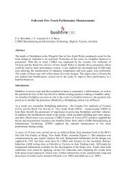
13Local earth fixingFigure 2.5Terminal compartmentTerminal 1 +24 VDCTerminal 2 24 V return (0 V)Terminal 3 4-20 mA output2.2.2 Output cable connectionsThe detector has two output modes:Terminal 4 Factory use onlyTerminal 5 Factory use only- Current source 4-20 mA (standard)- Current sink 4 - 20 mA (option)The mode is factory set, and shown on the identification plate of thedetector.2.2.2.1 3-wire output cable connectionThe cable connections are as follows:Terminal No l: +24V DCTerminal No 2: 0 V DC (24 V and signal return)Terminal No 3: Signal outputThe shield of the cable should be connected to instrument earth in thecentral control module, and left unterminated at the detector. Do notconnect clean earth conductors to the local earthing screw.