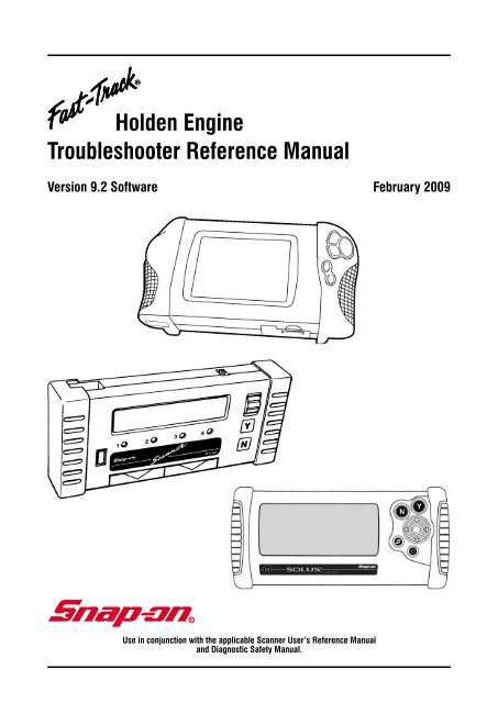
Holden Engine Troubleshooter Reference Manual - Snap-on Australia
Holden Engine Troubleshooter Reference Manual - Snap-on Australia
Holden Engine Troubleshooter Reference Manual - Snap-on Australia
- No tags were found...
You also want an ePaper? Increase the reach of your titles
YUMPU automatically turns print PDFs into web optimized ePapers that Google loves.
<str<strong>on</strong>g>Holden</str<strong>on</strong>g> <str<strong>on</strong>g>Reference</str<strong>on</strong>g> BulletinsRef. No. PageSubjectH001 9 VN Model (to Oct 1989) V6 wiring diagram and c<strong>on</strong>nectorsH002 11 VN Model (from Oct 1989) & VP Model V6 wiring diagram and c<strong>on</strong>nectorsH003 13 VN Model (to Oct 1989) V8 wiring diagram and c<strong>on</strong>nectorsH004 15 VN Model (from Oct 1989) & VP Model V8 wiring diagram and c<strong>on</strong>nectorsH005 17 VR <str<strong>on</strong>g>Manual</str<strong>on</strong>g> Model V6 wiring diagram and c<strong>on</strong>nectorsH006 19 VR Automatic Model V6 wiring diagram and c<strong>on</strong>nectorsH007 21 VR & VS <str<strong>on</strong>g>Manual</str<strong>on</strong>g> Model V8 wiring diagram and c<strong>on</strong>nectorsH008 23 VR & VS Automatic Model V8 wiring diagram and c<strong>on</strong>nectorsH009 25 VS Model V6 wiring diagram and c<strong>on</strong>nectorsH010 27 VT Model V6 wiring diagram and c<strong>on</strong>nectorsH011 29 VT Model V8 wiring diagram and c<strong>on</strong>nectorsH012 31 VX Model V6 c<strong>on</strong>nector diagramH013 32 VY Model V6 c<strong>on</strong>nector diagramH014 33 V6 Direct Fire Injecti<strong>on</strong> (DFI) Power Balance TestingH015 34 Fuel System Diagnosis Using Fuel Pump CurrentH016 35 V6 Crankshaft Sensor TestingH017 37 Integrator and Block Learn Functi<strong>on</strong>sH018 39 Short Term and L<strong>on</strong>g Term Fuel Trim Functi<strong>on</strong>sH019 41 3.8 Litre V6 Igniti<strong>on</strong> TestH020 43 Intake Air and Manifold Air Temperature Sensor Resistance ValuesH021 44 Knock Sensor TestH022 45 Quad Driver Circuit TestH023 46 5.0 Litre V8 Coil Resistance CheckH024 46 3.8 Litre V6 Coil Resistance CheckH025 47 VN (pre Oct 89) 5.0 Litre V8 Igniti<strong>on</strong> TestH026 48 VN (post Oct 89) to VS 5.0 Litre V8 Igniti<strong>on</strong> TestH027 49 VT 5.0 Litre V8 Igniti<strong>on</strong> TestH028 50 VR Model V6 <str<strong>on</strong>g>Manual</str<strong>on</strong>g> Transmissi<strong>on</strong> EST CheckH029 51 VR Model V6 Automatic Transmissi<strong>on</strong> EST CheckH030 52 VS & VT Model V6 EST CheckH031 53 VN, VP V8 Model & VR, VS (manual <strong>on</strong>ly) V8 Model EST CheckH032 54 VR & VS V8 (auto <strong>on</strong>ly) Model EST CheckH033 55 VT 5.0 Litre V8 Model EST CheckH034 56 VX & VY V6 Model EST CheckH035 57 Coolant Temperature Sensor Resistance CheckPAGE 7
PLEASE NOTE WIRING DIAGRAM WIRE COLOURS ARE GIVENAT THE PCM AND MAY NOT ALWAYS BE CORRECT DUE TOMANUFACTURING CHANGES IN PRODUCTION. ALSO WIRECOLOURS AT COMPONENTS AND SENSORS MAY NOT BE THESAME AS AT THE PCM.ALL CONNECTORS ARE VIEWED LOOKING INTO FACE OFCONNECTION.PAGE 8
H001VN Model (to Oct 1989) V6 Wiring DiagramPAGE 9
H001 VN Model (to Oct 1989) V6 C<strong>on</strong>nectorsPAGE 10
H002VN Model (from Oct 1989) & VP Model V6Wiring DiagramPAGE 11
H002 VN Model (from Oct 1989) & VP Model V6 C<strong>on</strong>nectorsPAGE 12
H003VN Model (to Oct 1989) V8 Wiring DiagramPAGE 13
H003 VN Model (to Oct 1989) V8 C<strong>on</strong>nectorsPAGE 14
H004VN Model (from Oct 1989) & VP Model V8Wiring DiagramPAGE 15
H004 VN Model (from Oct 1989) & VP Model V8 C<strong>on</strong>nectorsPAGE 16
H005VR <str<strong>on</strong>g>Manual</str<strong>on</strong>g> Model V6 Wiring DiagramPAGE 17
H005 VR <str<strong>on</strong>g>Manual</str<strong>on</strong>g> Model V6 C<strong>on</strong>nectorsPAGE 18
H006VR Automatic Model V6 Wiring DiagramPAGE 19
H006 VR Automatic Model V6 C<strong>on</strong>nectorsPAGE 20
H007VR & VS <str<strong>on</strong>g>Manual</str<strong>on</strong>g> Model V8 Wiring DiagramPAGE 21
H007 VR & VS <str<strong>on</strong>g>Manual</str<strong>on</strong>g> Model V8 C<strong>on</strong>nectorsPAGE 22
H008VR & VS Automatic Model V8 Wiring DiagramPAGE 23
H008 VR & VS Automatic Model V8 C<strong>on</strong>nectorsPAGE 24
H009VS Model V6 Wiring DiagramPAGE 25
H009 VS Model V6 C<strong>on</strong>nectorsPAGE 26
H010VT Model V6 Wiring DiagramPAGE 27
H010 VT Model V6 C<strong>on</strong>nectorsPAGE 28
H011VT Model 5.0 Litre V8 Wiring DiagramPAGE 29
H011 VT Model 5.0 Litre V8 C<strong>on</strong>nectorsPAGE 30
H012VX Model V6 C<strong>on</strong>nector DiagramPAGE 31
H013 VY Model V6 C<strong>on</strong>nector DiagramC/DPAGE 32
H014V6 Direct Fire Igniti<strong>on</strong> (DFI) Power Balance TestingPower Balance TestingYou can do a power balance test <strong>on</strong> a direct igniti<strong>on</strong> system by using short lengths of vacuumhose and a 12-volt test lamp. The vacuum hose must have a high carb<strong>on</strong> c<strong>on</strong>tent so that itwill c<strong>on</strong>duct sec<strong>on</strong>dary voltage. Install a short piece of hose between each coil terminal andits spark plug cable as per figure 1.The vacuum hose should be l<strong>on</strong>g enough to be exposed when the plug cable is c<strong>on</strong>nectedbut short enough that they do not touch any metal object.Figure 1: Vacuum hose c<strong>on</strong>necti<strong>on</strong> for power balance testing.Using a 12-volt test lamp c<strong>on</strong>nected to ground, touch each vacuum hose to short the cylinder.Note the engine speed as you short each cylinder. Then slowly move the test lamp probeaway from the hose and note the strength of the arc between the vacuum hose and thetest lamp probe. As with any power balance test, engine speed will decrease the least <strong>on</strong>a cylinder with a problem. Interpret the strength of the arc between the hose and the lampprobe as follows:Touch the vacuum hoses with the test lamp until you find little or no rpm drop. Then move theprobe away from the hose and note the arc. If the arc jumps a l<strong>on</strong>g distance to the groundedtest lamp, suspect an open circuit between the coil and the plug. Look for an open plugcable or plug or a very wide plug gap. If the arc jumps <strong>on</strong>ly a short distance to the groundedtest lamp, suspect a short circuit between the coil and the plug. Look for a shorted cable orplug, or a fouled, cracked, or carb<strong>on</strong> tracked spark plug, figure 2.Broken Spark Plug InsulatorFigure 2: Spark Plug Insulati<strong>on</strong>.The ceramic spark plug insulator can break near the base where it is hard to see, figure 15.This can cause a misfire. You may need to gently tap <strong>on</strong> the spark plug. If the insulator slidesdown, it will mask the spark, causing a misfire. You can also check the resistance betweenthe terminal and the centre electrode. Typically, the resistance should be 6000 ohms or less.A defective plug will often show an open circuit or high resistance.PAGE 33
H015 Fuel System Diagnosis Using Fuel Pump CurrentKnowing whether a running fuel pump is drawing too much or too little current can help youidentify a faulty fuel system comp<strong>on</strong>ent.To measure fuel pump current, you can use an ammeter or a DMM with an inductive probe.WARNING: High current flowing through faulty fuel pump circuits may damage a DMM. Do notuse a measuring tool whose current-rating is less than the current you expect to measure.If using an ammeter, remove the fuel pump fuse and c<strong>on</strong>nect the leads across the fuelterminals. If <strong>on</strong>ly using an inductive probe, attach its end around the positive feed wire to thefuel pump.With the test leads or probe hooked up, start and run the engine if possible. If trouble-shootingan intermittent problem, allow the engine to run l<strong>on</strong>g enough to give the fault an opportunityto present itself. Then record the key-<strong>on</strong> engine-running fuel pump current. Turn the igniti<strong>on</strong>switch to the OFF positi<strong>on</strong> and back to the ON positi<strong>on</strong> without restarting the vehicle. Afterthe fuel pump stops running (usually about 2 sec<strong>on</strong>ds), record the current again. Normallythis nominal current is 0 to 0.7 amps.If the problem affecting the vehicle prevents you from starting the engine, turn the key to theON positi<strong>on</strong>. Record the key-<strong>on</strong> engine-off current before the fuel pump stops running. Turn theigniti<strong>on</strong> switch to the OFF positi<strong>on</strong> and back to the ON positi<strong>on</strong> without restarting the vehicle.After the fuel pump stops running (usually about 2 sec<strong>on</strong>ds), record the nominal current.Subtract the nominal current from the key-<strong>on</strong> engine-off or key-<strong>on</strong> engine-running current toobtain the fuel pump current draw. Refer to table 1 to see if the current draw value falls withinspecificati<strong>on</strong>.If the fuel pump current is much lower than specificati<strong>on</strong>, suspect:• empty fuel tank• an open pump circuit• a damaged pulsator (dampener)• a leaking internal c<strong>on</strong>necti<strong>on</strong> between the pump and fuel line• a broken pressure regulator spring• a faulty fuel pumpIf the fuel pump current is much greater than specificati<strong>on</strong>, suspect a:• plugged fuel filter• restricted fuel hose• faulty fuel pumpFuel Pump Priming Operati<strong>on</strong>When the igniti<strong>on</strong> is turned <strong>on</strong>, the PCM for GM fuel injecti<strong>on</strong> systems energizes the fuel pumpfor about 2 sec<strong>on</strong>ds to prime the system. If the PCM does not get a tach (cranking) signalwithin the 2 sec<strong>on</strong>ds, it de-energizes the pump relay, figure 3. When cycling the igniti<strong>on</strong> topressurise the system for testing, leave the igniti<strong>on</strong> off for 15 sec<strong>on</strong>ds before turning it <strong>on</strong>again; or the PCM will not re-energize the pump relay.Note these systems hold residual pressure when the engine is off. Pressure can leak down,however, during a l<strong>on</strong>g engine-off period.PAGE 34
H016 c<strong>on</strong>tinued• Verify that the module and the sensors all have good grounds. Refer to diagrams forterminal identificati<strong>on</strong>.• If the engine does not start, tap the crank sensor lightly with a screwdriver handle. Ifthe engine then starts, the sensor may have an intermittent open or short circuit.You can use the Vantage Meter, an oscilloscope, a digital volt-ohmmeter (DVOM), or alight-emitting diode (LED) test lamp to check the sensor signal. C<strong>on</strong>nect test equipmentas shown in Figure 2. Set the scope for a 20-millisec<strong>on</strong>d (20 ms) sweep and 5.0 volts perdivisi<strong>on</strong>. The scope display for a good sensor should be similar to the patterns previouslyshown in Figure 1.• 1X and 3X Signals – Check these signals with either a DVOM, LED test lamp, or ascope. Leave the sensor c<strong>on</strong>nected and backprobe the correct terminals at the igniti<strong>on</strong>module; then crank the engine. DVOM dc voltage will fluctuate if the sensor is working.An LED will flash as the signal voltage goes high and low and actually provides a betterindicati<strong>on</strong> than a DVOM.• 18X Signal – This signal is too fast to check reliability with a DVOM or an LED. A scopeprovides the most reliable reading. As an alternative, set a DVOM <strong>on</strong> the 20- or 40- voltscale and c<strong>on</strong>nect the positive (+) lead to a battery positive (+) voltage. Backprobethe sensor signal terminal at the module with the DVOM negative (–) lead. Turn theigniti<strong>on</strong> <strong>on</strong> and bump the starter; do not crank the engine steadily. The DVOM readingshould be high (above 9 volts) when a blade of the interrupter ring is in the sensorslot (window closed) and low (below 3 volts) when the blade is out of the slot (windowopen). It may take several tries to alternately positi<strong>on</strong> a blade in and out of the sensorslot and verify the high and low signal voltage levels.PAGE 36
H017Integrator and Block Learn Functi<strong>on</strong>sThe integrator and black learn functi<strong>on</strong>s are resp<strong>on</strong>sible for making minor adjustments tothe air-fuel mixture <strong>on</strong> fuel injected vehicles. The integrator makes temporary, short-termcorrecti<strong>on</strong>s, while block learn makes more permanent, l<strong>on</strong>g-term correcti<strong>on</strong>s. Integrator andblock learn give useful diagnostic values <strong>on</strong>ly when the car is running in closed loop.IntegratorThe integrator m<strong>on</strong>itors the oxygen sensor output voltage and adds or subtracts fuel,depending <strong>on</strong> the lean or rich c<strong>on</strong>diti<strong>on</strong> of the O2 sensor. Think of the integrator value asrepresenting injector <strong>on</strong> time, the larger the number, the more fuel delivered. Even thoughintegrator values go from 0 to 255, typically a low number would be 58 and a high numberwould be 198.Block LearnBlock learn m<strong>on</strong>itors the integrator value and compares it to engine operating ranges at variouscombinati<strong>on</strong>s of rpm and load. Load is determined by engine speed and MAP. A plot of rpmversus engine load is used to determine the performance boundaries. These performanceboundaries are called cells or blocks. VN and VP models have 16 different cells.The PCM has different fuel delivery values stored in each block. Block 0 is idle with no load,and block 15 is maximum rpm and maximum load. As the operating range changes to adifferent block, the fuel delivery changes to the operating value stored in that block.If the integrator is far enough from 128, the PCM changes the block learn value. Once theblock learn value is changed, it should force the integrator back to 128. If the mixture is stillnot correct, based <strong>on</strong> the O2 sensor, the integrator will c<strong>on</strong>tinue to have a large divisi<strong>on</strong> from128 and the block learn value will c<strong>on</strong>tinue to change until the integrator value becomesbalanced.When integrator increases or decreases, block learn resp<strong>on</strong>ds by making changes in thesame directi<strong>on</strong>. As block learn makes its l<strong>on</strong>g-term correcti<strong>on</strong>s, the need for the integratorshort-term correcti<strong>on</strong> is reduced. In a properly operating system, integrator will adjust thefuel mixture until block learn takes over, and then integrator will return to its normal valueof 128.Both the integrator and block learn have limits that vary, depending <strong>on</strong> the vehicle. Once aproblem exceeds the block learn correcti<strong>on</strong> limit, the integrator goes to its correcti<strong>on</strong> limit,and the check engine lamp will light.Block Learn Memory StorageThe values stored in the block learn cells remain in memory when the igniti<strong>on</strong> is turned OFF.Up<strong>on</strong> restart, the fuel delivery for a given block is based <strong>on</strong> the stored value. Disc<strong>on</strong>nectingthe battery or power supply to the PCM will cause the fuel trim memory to be lost.PAGE 37
H017 c<strong>on</strong>tinuedUsing Block Learn and Integrator To Find Vacuum LeaksA block learn value that is high at idle, and normal at 3000 rpm, indicates a possible vacuumleak. This is because a vacuum leak is a larger percentage of total air flow at idle than at3000 rpm. Thus, the fuel mixture needs more correcti<strong>on</strong> at idle.Integrator can help you find a vacuum leak. Pinch off the vacuum hoses as close as possibleto the intake manifold while observing the integrator value. A sudden drop in the readingwhile pinching a hose indicates a vacuum leak in that hose, or an attached comp<strong>on</strong>ent.Using Block Learn To Diagnose Fuel Flow ProblemsA block learn value that is normal at idle and high at 3000 rpm indicates a possible fuel flowproblem. This is because the engine needs more fuel at 3000 rpm than at idle. Thus, the fuelmixture needs more correcti<strong>on</strong> at high rpm. Suspect a dirty fuel filter or a weak fuel pump.A block learn value that is high at both idle and 3000 rpm indicates dirty fuel injectors, orlow fuel pressure. This is because fuel injector flow and fuel pressure affects the engine atall rpm.Using Block Learn To Diagnose A Rich C<strong>on</strong>diti<strong>on</strong>A block learn reading that is low at idle – 100 or below – or low at 3000 rpm indicates arich c<strong>on</strong>diti<strong>on</strong>. Possible areas of c<strong>on</strong>cern at fuel-c<strong>on</strong>taminated oil, a leaking fuel pressureregulator, a leaking fuel injector, or high fuel pressure.PAGE 38
H018Short Term and L<strong>on</strong>g Term Fuel Trim Functi<strong>on</strong>sThe short term fuel trim (STFT) and l<strong>on</strong>g term fuel trim (LTFT) functi<strong>on</strong>s are resp<strong>on</strong>sible formaking minor adjustments to the air-fuel mixture <strong>on</strong> fuel injected vehicles. The STFT makestemporary, short-term correcti<strong>on</strong>s, while LTFT makes more permanent, l<strong>on</strong>g-term correcti<strong>on</strong>s.LTFT and STFT give useful diagnostic values <strong>on</strong>ly when the car is running in closed loop.Short Term Fuel TrimThe STFT m<strong>on</strong>itors the oxygen sensor output voltage and adds or subtracts fuel, depending<strong>on</strong> the lean or rich c<strong>on</strong>diti<strong>on</strong> of the O2 sensor. Think of the STFT value as representinginjector <strong>on</strong> time, value above 0%, the more fuel delivered. Even though STFT values gofrom -100% to +100%, typically a low number would be less than -20% and a high numberwould above 25%.L<strong>on</strong>g Term Fuel TrimLTFT m<strong>on</strong>itors the STFT value and compares it to engine operating ranges at variouscombinati<strong>on</strong>s of rpm and load. Load is determined by engine speed and MAP. A plot of rpmversus engine load is used to determine the performance boundaries. These performanceboundaries are called cells or blocks. VR and VS models have 24 and VT models <strong>on</strong>wardshave 34 different cells.The PCM has different fuel delivery values stored in each cell. As the operating range changesto a different cell, the fuel delivery changes to the operating value stored in that cell.If the STFT is far enough from 0%, the PCM changes the LTFT value. Once the LTFT valueis changed, it should force the STFT back to 0%. If the mixture is still not correct, based <strong>on</strong>the O2 sensor, the STFT will c<strong>on</strong>tinue to have a large divisi<strong>on</strong> from 0% and the LTFT valuewill c<strong>on</strong>tinue to change until the STFT value becomes balanced.When STFT increases or decreases, LTFT resp<strong>on</strong>ds by making changes in the same directi<strong>on</strong>.As LTFT makes its l<strong>on</strong>g-term correcti<strong>on</strong>s, the need for the STFT short-term correcti<strong>on</strong> isreduced. In a properly operating system, STFT will adjust the fuel mixture until STFT takesover, and then STFT will return to its normal value of 0%.Both the STFT and LTFT have limits that vary, depending <strong>on</strong> the vehicle. Once a problemexceeds the LTFT correcti<strong>on</strong> limit, the STFT goes to its correcti<strong>on</strong> limit, and the check enginelamp will light.LTFT Memory StorageThe values stored in the block learn cells remain in memory when the igniti<strong>on</strong> is turned OFF.Up<strong>on</strong> restart, the fuel delivery for a given block is based <strong>on</strong> the stored value. Disc<strong>on</strong>nectingthe battery or power supply to the PCM will cause the fuel trim memory to be lost.PAGE 39
H018 c<strong>on</strong>tinuedUsing Fuel Trim Values To Find Vacuum LeaksA LTFT value that is high at idle, and normal at 3000 rpm, indicates a possible vacuum leak.This is because a vacuum leak is a larger percentage of total air flow at idle than at 3000rpm. Thus, the fuel mixture needs more correcti<strong>on</strong> at idle.STFT can help you find a vacuum leak. Pinch off the vacuum hoses as close as possibleto the intake manifold while observing the STFT value. A sudden drop in the reading whilepinching a hose indicates a vacuum leak in that hose, or an attached comp<strong>on</strong>ent.Using LTFT To Diagnose Fuel Flow ProblemsA LTFT value that is normal at idle and high at 3000 rpm indicates a possible fuel flow problem.This is because the engine needs more fuel at 3000 rpm than at idle. Thus, the fuel mixtureneeds more correcti<strong>on</strong> at high rpm. Suspect a dirty fuel filter or a weak fuel pump.A LTFT value that is high at both idle and 3000 rpm indicates dirty fuel injectors, or low fuelpressure. This is because fuel injector flow and fuel pressure affects the engine at all rpm.Using LTFT To Diagnose A Rich C<strong>on</strong>diti<strong>on</strong>A LTFT reading that is low at idle (below -10%) at idle or low at 3000 rpm indicates a richc<strong>on</strong>diti<strong>on</strong>. Possible areas of c<strong>on</strong>cern at fuel-c<strong>on</strong>taminated oil, a leaking fuel pressure regulator,a leaking fuel injector, or high fuel pressure.PAGE 40
H0193.8 Litre V6 Igniti<strong>on</strong> TestThis test requires the use of 3 paper clips, 2 straightened for probing and earthing and 1 bentto a narrow “U” shape for bridging. The use of <str<strong>on</strong>g>Snap</str<strong>on</strong>g>-<strong>on</strong> part number MT3000430A5R backprobes are recommended for probing but paperclips can be used if not available. Be carefulnot to allow any probes to touch or earth out.Follow test as follows:1. a) With igniti<strong>on</strong> OFF and DFI module 14-pin c<strong>on</strong>nector disc<strong>on</strong>nected, bridge c<strong>on</strong>nectorterminals N (white/black) and P (VN pre-Oct 89 pink/VN post-Oct 89, VP, VR, VSred/VT <strong>on</strong>wards green).b) Insert probe into c<strong>on</strong>nector terminal M (grey/red) and c<strong>on</strong>nect it to earth.c) Probe c<strong>on</strong>nector terminal H (blue/white) with a testlight which is c<strong>on</strong>nected to 12Vpositive.d) Switch igniti<strong>on</strong> <strong>on</strong> and slowly turn engine over by hand (28mm socket). Check iftestlight goes ‘<strong>on</strong>’ and ‘off’ as 3X interrupter blades pass through crank sensor. Iftestlight goes ‘<strong>on</strong>’ and ‘off’ go to tip 2. If not check for c<strong>on</strong>tinuity and no shorts ofwhite/black, blue/white and grey/red wires from DFI c<strong>on</strong>nector to crank sensor. Ifwiring is okay then suspect crank sensor.2. a) Switch igniti<strong>on</strong> offb) Remove testlight probe from c<strong>on</strong>nector terminal H (blue/white) and insert probeinto c<strong>on</strong>nector terminal G (blue/yellow).c) Switch igniti<strong>on</strong> <strong>on</strong> and slowly turn engine over by hand. Testlight should go ‘<strong>on</strong>’and ‘off’ as 18x interrupter ring passes through crank sensor.If testlight goes ‘<strong>on</strong>’ and ‘off’ go to tip 3.If not, check for c<strong>on</strong>tinuity and no shorts of blue/yellow wire from crank sensor toDFI module pin G. If wiring okay, suspect faulty crank sensor.3. a) Switch igniti<strong>on</strong> off and remove all leads and refit 14-pin c<strong>on</strong>nector to DFI module.b) Remove coil packs from top of DFI module including the terminals <strong>on</strong> base ofcoils.c) Fit testlight across corresp<strong>on</strong>ding coil terminals from DFI module.d) With engine cranking, testlight should blink. This test should be d<strong>on</strong>e across allthree corresp<strong>on</strong>ding coil DFI terminals.If testlight blinks across all three, go to tip 4.If testlight did not blink across any <strong>on</strong>e of the DFI terminals the suspect faulty DFImodule.PAGE 41
H019 c<strong>on</strong>tinued4. a) Check coil primary resistance by using an ohmmeter across the undersidecorresp<strong>on</strong>ding terminals of each coil. Reading should be 0.30 ohms to 1.5 ohmsacross all these primary terminals of coils.If reading is okay, go to tip 5.If reading is out, suspect faulty igniti<strong>on</strong> coil.5. b) Check coil sec<strong>on</strong>dary resistance by using an ohmmeter across the corresp<strong>on</strong>dingplug lead posts of all three igniti<strong>on</strong> coils.If combined coil pack (pre-1999) If separate coil packs (post-1990)reading should bereading should be10 Kohms to 14 Kohms 5 Kohms to 7 KohmsIf any coil is out of range or if <strong>on</strong>e coil differs from other two by more than 1 Kohm,then suspect faulty coil.If all tests pass and igniti<strong>on</strong> tests and plugs are okay, this indicates igniti<strong>on</strong> systemshould operate. Check for poor c<strong>on</strong>necti<strong>on</strong>s etc for possible cause of intermittentfault.NOTE: After test when comp<strong>on</strong>ents are reinstalled, switch igniti<strong>on</strong> ON and reinputback to previous Scanner menu selecti<strong>on</strong> screen to c<strong>on</strong>tinue with tip.PAGE 42
H020Intake Air Tempterature (IAT) andManifold Air Temperature (MAT) SensorResistance to Temperature Values3.8 Litre V6 ModelsVN, VP & VR Models°C OHMS100 18570 45038 1,80020 3,4004 7,500-7 13,500-18 25,000-40 100,700VS, VT, VX & VY Models°C OHMS °C OHMS-40 102,129 60 679-35 73,345 65 566-30 53,253 70 475-25 39,066 75 400-20 28,940 80 338-15 21,638 85 287-10 16,321 90 245-5 12,414 95 2100 9,517 100 1805 7,355 105 15610 5,729 110 13515 4,497 115 11720 3,555 120 10225 2,830 125 8930 2,268 130 7935 1,829 135 6940 1,483 140 6145 1,210 145 5450 993 150 4855 8195.0 Litre V8 ModelsAll Models°C OHMS100 18570 45038 1,80020 3,4004 7,500-7 13,500-18 25,000-40 100,700PAGE 43
H021 VS & VT 3.8 Litre V6 Knock Sensor Test1) With igniti<strong>on</strong> off disc<strong>on</strong>nect PCM c<strong>on</strong>nectors.2) Check resistance of PCM c<strong>on</strong>nector pin C12 (white/red) to ground.If reading approx. 50 Kohms go to step 4.If reading approx. 100 Kohms go to step 3.If reading not 50 Kohms or 100 Kohms check wiring from PCM c<strong>on</strong>nector pin C12(white/red) to knock sensors for open or short. If wiring is okay then suspect faultyknock sensors.3) If reading was 100 Kohms then <strong>on</strong>e knock sensor or wiring to <strong>on</strong>e knock sensor hasopen circuit. Remove c<strong>on</strong>nector from knock sensors and check centre knock sensorterminal to ground resistance to see if <strong>on</strong>e is open. If knock sensors are not open, traceopen in wiring from PCM c<strong>on</strong>nector pin C12 (white/red) to <strong>on</strong>e knock sensor c<strong>on</strong>nectorand repair as needed.4) If reading was 50 Kohms rec<strong>on</strong>nect PCM c<strong>on</strong>nectors. With digital voltmeter set <strong>on</strong>AC voltage backprobe PCM c<strong>on</strong>nector pin C12 (white/red) with +ve lead and -ve toground. Top alternator bracket with hammer while observing reading. If reading alwaysless than 50mV AC then suspect faulty knock sensors. If reading goes over 50mV ACthen suspect intermittent fault. Check all c<strong>on</strong>nectors.NOTE: After test when comp<strong>on</strong>ents are reinstalled, switch igniti<strong>on</strong> <strong>on</strong> and reinput backto previous Scanner menu selecti<strong>on</strong> screen to c<strong>on</strong>tinue with tip.PAGE 44
H022Quad Driver Circuit CheckDisc<strong>on</strong>nect PCM c<strong>on</strong>nector and switch igniti<strong>on</strong> <strong>on</strong>.Check for battery voltage at PCM pin F4 (green/black). If not check circuit from A/C comprelay to pin F4 for open or short.If battery voltage at pin F4, check for battery voltage at pin F5 (blue) with igniti<strong>on</strong> <strong>on</strong>. If notcheck circuit from start relay to PCM pin F5.If battery voltage at pin F5, check for battery voltage at PCM pin F6 (blue/white) with igniti<strong>on</strong><strong>on</strong>. If not check circuit from fan relay to PCM pin F5 for open or short.If battery voltage at pin F6, switch igniti<strong>on</strong> off and check for open or short in wiring from PCMpin F7 (black/white) to ABS/Trac C<strong>on</strong>trol ECU.NOTE: After test when comp<strong>on</strong>ents are reinstalled, switch igniti<strong>on</strong> <strong>on</strong> and reinput back toprevious Scanner menu selecti<strong>on</strong> screen to c<strong>on</strong>tinue with tip.PAGE 45
H023 5.0 Litre V8 Coil Resistance CheckPrimary resistance across +ve and -ve of coil terminals 0.76 to 0.84 ohms.Sec<strong>on</strong>dary resistance across -ve coil terminal and high tensi<strong>on</strong> post 4.5 Kohms to 6.0Kohms.Always check for cracks in coil casing particularly near mounting bracket.After testing, reinstall comp<strong>on</strong>ents and switch igniti<strong>on</strong> <strong>on</strong> to c<strong>on</strong>tinue using the<str<strong>on</strong>g>Troubleshooter</str<strong>on</strong>g>.H024 3.8 Litre V6 Coil Resistance CheckOne piece combinedcoil pack typeIndividualcoil pack typePrimary resistance checked 0.3 ohm to 1.5 ohm 0.3 ohm to 1.5 ohmacross corresp<strong>on</strong>ding terminals<strong>on</strong> underside of coilSec<strong>on</strong>dary resistance 10 Kohm to 14 Kohm 5 Kohm to 7 Kohmchecked across correp<strong>on</strong>dinghigh tensi<strong>on</strong> postsNOTE: If any coil out of range or if <strong>on</strong>e coil sec<strong>on</strong>dary reading differs from other two by morethan 1 Kohm then suspect faulty coil.After testing, reinstall comp<strong>on</strong>ents and switch igniti<strong>on</strong> <strong>on</strong> to c<strong>on</strong>tinue using the<str<strong>on</strong>g>Troubleshooter</str<strong>on</strong>g>.PAGE 46
H025VN (pre Oct 89) 5.0 Litre V8 Igniti<strong>on</strong> Test1. Disc<strong>on</strong>nect the 6-pin c<strong>on</strong>nector from the igniti<strong>on</strong> module. With the testight c<strong>on</strong>nectedto 12V +ve, probe black wire of c<strong>on</strong>nector. Testlight should light.If okay, go to tip 2. If not, repair earth circuit as necessary.2. Switch igniti<strong>on</strong> <strong>on</strong>. With testlight c<strong>on</strong>nected to earth, probe pink wire of c<strong>on</strong>nector.Testlight should light.If okay, go to tip 3. If not, check power supply to igniti<strong>on</strong> module from igniti<strong>on</strong> switchthrough fuse 11.3. With testlight still c<strong>on</strong>nected to earth and igniti<strong>on</strong> <strong>on</strong>, probe brown wire of c<strong>on</strong>nector.Testlight should light.If okay, go to tip 4. If not, check power supply with igniti<strong>on</strong> <strong>on</strong> to +ve of coil fromigniti<strong>on</strong> switch through fuse 11. If power supply to the +ve and -ve of coil okay, carryout resistance check across +ve and -ve of coil terminals. Resistance should be 0.76ohms to 0.84 ohms. If coil resistance okay, check wiring from brown wire of igniti<strong>on</strong>module c<strong>on</strong>nector to -ve coil terminal c<strong>on</strong>nector for open or short circuit and repair asnecessary.4. Refit 6-pin c<strong>on</strong>nector to igniti<strong>on</strong> module. With testlight c<strong>on</strong>nected to 12V +ve, probetacho wire or brown wire of 6-pin c<strong>on</strong>nector. Check for blinking of testlight while crankingengine.If testlight blinks but igniti<strong>on</strong> system has no spark, check for defective dist cap, roto oractual coil. If testlight did not blink, got to tip 5.5. Disc<strong>on</strong>nect 6-pin c<strong>on</strong>nector to igniti<strong>on</strong> module. Install a bridge wire between grey/redand black wires of c<strong>on</strong>nector. Install a sec<strong>on</strong>d bridge wire between white/black andpink wires of c<strong>on</strong>nector. With a low power LED testlight c<strong>on</strong>nected to 12V +ve, probeblue/white terminal of c<strong>on</strong>nector. Check for blinking testlight while cranking engine.If testlight blinks, suspect faulty igniti<strong>on</strong> module. If testlight did not blink, check white/black, grey/red and blue/white wires from igniti<strong>on</strong> module to distributor for open orshorts. If wiring okay suspect faulty hall effect crank sensor in distributor.After testing, reinstall comp<strong>on</strong>ents and switch igniti<strong>on</strong> <strong>on</strong> to c<strong>on</strong>tinue using the<str<strong>on</strong>g>Troubleshooter</str<strong>on</strong>g>.PAGE 47
H026VN (post Oct 89) to VS 5.0 Litre V8 Igniti<strong>on</strong> Test1. Disc<strong>on</strong>nect the 6-pin c<strong>on</strong>nector from the igniti<strong>on</strong> module. With the testight c<strong>on</strong>nectedto 12V +ve, probe black wire of c<strong>on</strong>nector. Testlight should light.If okay, go to tip 2. If not, repair earth circuit as necessary.2. Switch igniti<strong>on</strong> <strong>on</strong>. With testlight c<strong>on</strong>nected to earth, probe red wire of c<strong>on</strong>nector.Testlight should light.If okay, go to tip 3. If not, check power supply to igniti<strong>on</strong> module from EFI relay.3. With testlight still c<strong>on</strong>nected to earth and igniti<strong>on</strong> <strong>on</strong>, probe brown wire of c<strong>on</strong>nector.Testlight should light.If okay, go to tip 4. If not, check power supply with igniti<strong>on</strong> <strong>on</strong> to +ve of coil from EFIrelay. If power supply to the +ve and -ve of coil okay, carry out resistance check across+ve and -ve of coil terminals. Resistance should be 0.76 ohms to 0.84 ohms. If coilresistance okay, check wiring from brown wire of igniti<strong>on</strong> module c<strong>on</strong>nector to -ve coilterminal c<strong>on</strong>nector for open or short circuit and repair as necessary.4. Refit 6-pin c<strong>on</strong>nector to igniti<strong>on</strong> module. With testlight c<strong>on</strong>nected to 12V +ve, probetacho wire or brown wire of 6-pin c<strong>on</strong>nector. Check for blinking of testlight while crankingengine.If testlight blinks but igniti<strong>on</strong> system has no spark, check for defective dist cap, roto oractual coil. If testlight did not blink, got to tip 5.5. Disc<strong>on</strong>nect 6-pin c<strong>on</strong>nector to igniti<strong>on</strong> module. Install a bridge wire between grey/redand black wires of c<strong>on</strong>nector. Install a sec<strong>on</strong>d bridge wire between white/black andred wires of c<strong>on</strong>nector. With a low power LED testlight c<strong>on</strong>nected to 12V +ve, probeblue/white terminal of c<strong>on</strong>nector. Check for blinking testlight while cranking engine.If testlight blinks, suspect faulty igniti<strong>on</strong> module. If testlight did not blink, check white/black, grey/red and blue/white wires from igniti<strong>on</strong> module to distributor for open orshorts. If wiring okay suspect faulty hall effect crank sensor in distributor.After testing, reinstall comp<strong>on</strong>ents and switch igniti<strong>on</strong> <strong>on</strong> to c<strong>on</strong>tinue using the<str<strong>on</strong>g>Troubleshooter</str<strong>on</strong>g>.PAGE 48
H027VT 5.0 Litre V8 Igniti<strong>on</strong> Test1. Disc<strong>on</strong>nect the 6-pin c<strong>on</strong>nector from the igniti<strong>on</strong> module. With the testight c<strong>on</strong>nectedto 12V +ve, probe black/red wire of c<strong>on</strong>nector. Testlight should light.If okay, go to tip 2. If not, repair earth circuit as necessary.2. Switch igniti<strong>on</strong> <strong>on</strong>. With testlight c<strong>on</strong>nected to earth, probe red wire of c<strong>on</strong>nector.Testlight should light.If okay, go to tip 3. If not, check power supply to igniti<strong>on</strong> module from EFI relay.3. With testlight still c<strong>on</strong>nected to earth and igniti<strong>on</strong> <strong>on</strong>, probe brown/red wire of c<strong>on</strong>nector.Testlight should light.If okay, go to tip 4. If not, check power supply with igniti<strong>on</strong> <strong>on</strong> to +ve of coil fromigniti<strong>on</strong> switch through fuse 35. If power supply to the +ve and -ve of coil okay, carryout resistance check across +ve and -ve of coil terminals. Resistance should be 0.76ohms to 0.84 ohms. If coil resistance okay, check wiring from brown wire of igniti<strong>on</strong>module c<strong>on</strong>nector to -ve coil terminal c<strong>on</strong>nector for open or short circuit and repair asnecessary.4. Refit 6-pin c<strong>on</strong>nector to igniti<strong>on</strong> module. With testlight c<strong>on</strong>nected to 12V +ve, probetacho wire or brown/red wire of 6-pin c<strong>on</strong>nector. Check for blinking of testlight whilecranking engine.If testlight blinks but igniti<strong>on</strong> system has no spark, check for defective dist cap, roto oractual coil. If testlight did not blink, got to tip 5.5. Disc<strong>on</strong>nect 6-pin c<strong>on</strong>nector to igniti<strong>on</strong> module. Install a bridge wire between grey/redand black/red wires of c<strong>on</strong>nector. Install a sec<strong>on</strong>d bridge wire between white/black andred wires of c<strong>on</strong>nector. With a low power LED testlight c<strong>on</strong>nected to 12V +ve, probeblue/white terminal of c<strong>on</strong>nector. Check for blinking testlight while cranking engine.If testlight blinks, suspect faulty igniti<strong>on</strong> module. If testlight did not blink, check white/black, grey/red and blue/white wires from igniti<strong>on</strong> module to distributor for open orshorts. If wiring okay suspect faulty hall effect crank sensor in distributor.After testing, reinstall comp<strong>on</strong>ents and switch igniti<strong>on</strong> <strong>on</strong> to c<strong>on</strong>tinue using the<str<strong>on</strong>g>Troubleshooter</str<strong>on</strong>g>.PAGE 49
H028VR Model V6 <str<strong>on</strong>g>Manual</str<strong>on</strong>g> Transmissi<strong>on</strong>Electr<strong>on</strong>ic Spark Timing (EST) Check1. Disc<strong>on</strong>nect PCM c<strong>on</strong>nectors. Switch igniti<strong>on</strong> <strong>on</strong> and check resistance of PCM c<strong>on</strong>nectorpin D4 (white) to ground.If reading under 500 ohms, go to tip 2.If reading over 500 ohms, check for open in wiring from PCM pin D4 (white) to DFImodule pin A (white) or for poor c<strong>on</strong>necti<strong>on</strong> at DFI module and repair as necessary.If wiring and circuit okay, suspect faulty DFI module.2. Back probe PCM c<strong>on</strong>nector pin D5 (tan/black) with a testlight which is c<strong>on</strong>nected to12V positive.If testlight off, go to tip 3.If testlight <strong>on</strong>, disc<strong>on</strong>nect DFI module c<strong>on</strong>nector.If testlight then goes off, suspect faulty DFI module.If testlight stayed <strong>on</strong> with DFI module disc<strong>on</strong>nected then trace and repair short in wiringfrom PCM pin D5 (tan/black) to DFI module pin B (tan/black).3. Check resistance at PCM c<strong>on</strong>nector pin D4 (white) to ground while probing testlightwhich is c<strong>on</strong>nected to 12V positive <strong>on</strong> to PCM c<strong>on</strong>nector pin D5 (tan/black).Reading should change from under 500 ohms to over 5000 ohms when testlight isplaced <strong>on</strong> PCM c<strong>on</strong>nector pin D5 (tan/black).If reading changes, suggest to reassemble and recheck if code returns. If code returnsthen suspect PCM or c<strong>on</strong>necti<strong>on</strong>.If reading did not change, disc<strong>on</strong>nect DFI module c<strong>on</strong>nector while still checkingresistance at PCM pin D4 (white) to ground.If reading changes to open circuit, check for suspect short of wiring from PCM c<strong>on</strong>nectorpin D5 (tan/black) to ground.PAGE 50
H029VR Model V6 Automatic Transmissi<strong>on</strong>Electr<strong>on</strong>ic Spark Timing (EST) Check1. Disc<strong>on</strong>nect PCM c<strong>on</strong>nectors. Switch igniti<strong>on</strong> <strong>on</strong> and check resistance of PCM c<strong>on</strong>nectorpin D11 (white) to ground.If reading under 500 ohms, go to tip 2.If reading over 500 ohms, check for open in wiring from PCM pin D11 (white) toDFI module pin A (white) or check for poor c<strong>on</strong>necti<strong>on</strong> at DFI module and repair asnecessary.If wiring and circuit okay, suspect faulty DFI module.2. Back probe PCM c<strong>on</strong>nector pin D12 (tan/black) with a testlight which is c<strong>on</strong>nected to12V positive.If testlight off, go to tip 3.If testlight <strong>on</strong>, disc<strong>on</strong>nect DFI module c<strong>on</strong>nector.If testlight then goes off, suspect faulty DFI module.If testlight stayed <strong>on</strong> with DFI module disc<strong>on</strong>nected then trace and repair short in wiringfrom PCM pin D12 (tan/black) to DFI module pin B (tan/black).3. Check resistance at PCM c<strong>on</strong>nector pin D11 (white) to ground while probing testlightwhich is c<strong>on</strong>nected to 12V positive <strong>on</strong> to PCM c<strong>on</strong>nector pin D12 (tan/black).Reading should change from under 500 ohms to over 5000 ohms when testlight isplaced <strong>on</strong> PCM c<strong>on</strong>nector pin D12 (tan/black).If reading changes, suggest to reassemble and recheck if code returns. If code returnsthen suspect PCM or c<strong>on</strong>necti<strong>on</strong>.If reading did not change, disc<strong>on</strong>nect DFI module c<strong>on</strong>nector while still checkingresistance at PCM pin D11 (white) to ground.If reading changes to open circuit, check for suspect short of wiring from PCM c<strong>on</strong>nectorpin D12 (tan/black) to ground.PAGE 51
H030VS & VT 3.8 Litre V6 Electr<strong>on</strong>ic Spark Timing (EST)1. Disc<strong>on</strong>nect DFI module c<strong>on</strong>nector. Check voltage reading at DFI c<strong>on</strong>nector A (white)with the igniti<strong>on</strong> <strong>on</strong>.If reading is over 0.5V, go to tip 4.If reading is under 0.5V, probe testlight which is c<strong>on</strong>nected to 12V positive to DFI modulec<strong>on</strong>nector pin A (white).If testlight is off, go to tip 2.If testlight in <strong>on</strong>, switch off igniti<strong>on</strong> and disc<strong>on</strong>nect PCM c<strong>on</strong>nectors. Switch back <strong>on</strong>and check if testlight is still <strong>on</strong> with testlight still probing DFI c<strong>on</strong>nector pin A (white).If testlight is now off, then suspect faulty PCM.If testlight remains <strong>on</strong>, trace and repair short to earth of wiring from PCM pin D10 (white)to DFI module c<strong>on</strong>nector pin A (white).2. With DFI module still disc<strong>on</strong>nected, probe testlight which is c<strong>on</strong>nected to 12V positiveto DFI c<strong>on</strong>nector pin B (tan/black) and switch igniti<strong>on</strong> <strong>on</strong>.If testlight is <strong>on</strong>, go to tip 3.If testlight is off, check c<strong>on</strong>necti<strong>on</strong> and wiring for open circuit from PCM pin D9 (tan/black) to DFI module c<strong>on</strong>nector pin B (tan/black).If wiring and c<strong>on</strong>nector okay, switch igniti<strong>on</strong> off and rec<strong>on</strong>nect DFI module c<strong>on</strong>nector.Disc<strong>on</strong>nect PCM c<strong>on</strong>nectors and switch igniti<strong>on</strong> <strong>on</strong>. Check resistance of PCM harnessc<strong>on</strong>nector pin D10 (white) to ground while placing testlight which is c<strong>on</strong>nected to 12Vpositive to PCM c<strong>on</strong>nector pin D9 (tan/black).If reading goes from under 300 ohms to over 6000 ohms when testlight c<strong>on</strong>tacts ecuc<strong>on</strong>nector pin D9 (tan/black) then suspect faulty PCM. If reading does not change thensuspect DFI module.3. Switch off igniti<strong>on</strong> and disc<strong>on</strong>nect PCM c<strong>on</strong>nectors and DFI module c<strong>on</strong>nector. Withtestlight c<strong>on</strong>nected to 12V positive, probe DFI c<strong>on</strong>nector pin B (tan/black).If testlight does not come <strong>on</strong>, then suspect faulty PCM.If testlight comes <strong>on</strong>, trace and repair short to ground of wiring from PCM pin D9 (tan/black) to DFI module pin B (tan/black).4. Switch igniti<strong>on</strong> off and disc<strong>on</strong>nect PCM c<strong>on</strong>nector. Check voltage at DFI modulec<strong>on</strong>nector pin A (white) with the igniti<strong>on</strong> <strong>on</strong>.If reading is under 0.5V then suspect faulty DFI module.If reading is still over 0.5V, trace and repair short to power of wiring from PCM pin D10(white) to DFI module c<strong>on</strong>nector pin A (white).PAGE 52
H031VN, VP 5.0 Litre V8 Model andVR, VS 5.0 Litre <str<strong>on</strong>g>Manual</str<strong>on</strong>g> Transmissi<strong>on</strong> ModelElectr<strong>on</strong>ic Spark Timing (EST) Check1. Disc<strong>on</strong>nect PCM c<strong>on</strong>nectors. Switch igniti<strong>on</strong> <strong>on</strong> and check resistance of PCM c<strong>on</strong>nectorpin D4 (white) to ground.If reading under 500 ohms, go to tip 2.If reading over 500 ohms, check for open in wiring from PCM pin D4 (white) to igniti<strong>on</strong>module white wire or check for poor c<strong>on</strong>necti<strong>on</strong> at igniti<strong>on</strong> module and repair asnecessary.If wiring and circuit okay, suspect faulty igniti<strong>on</strong> module.2. Back probe PCM c<strong>on</strong>nector pin D5 (tan/black) with a testlight which is c<strong>on</strong>nected to12V positive.If testlight off, go to tip 3.If testlight <strong>on</strong>, disc<strong>on</strong>nect 4-pin igniti<strong>on</strong> module c<strong>on</strong>nector.If testlight then goes off, suspect faulty igniti<strong>on</strong> module.If testlight stayed <strong>on</strong> with igniti<strong>on</strong> module disc<strong>on</strong>nected then trace and repair short inwiring from PCM pin D5 (tan/black) to igniti<strong>on</strong> module tan/black wire.3. Check resistance at PCM c<strong>on</strong>nector pin D4 (white) to ground while probing testlightwhich is c<strong>on</strong>nected to 12V positive <strong>on</strong> to PCM c<strong>on</strong>nector pin D5 (tan/black).Reading should change from under 500 ohms to over 5000 ohms when testlight isplaced <strong>on</strong> PCM c<strong>on</strong>nector pin D5 (tan/black).If reading changes, suggest to reassemble and recheck if code returns. If code returnsthen suspect PCM or c<strong>on</strong>necti<strong>on</strong>.If reading did not change, disc<strong>on</strong>nect igniti<strong>on</strong> module c<strong>on</strong>nectors while still checkingresistance at PCM pin D4 (white) to ground.If reading changes to open circuit, check for suspect short of wiring from PCM c<strong>on</strong>nectorpin D5 (tan/black) to ground.PAGE 53
H032VR, VS 5.0 Litre V8 Automatic Transmissi<strong>on</strong> ModelElectr<strong>on</strong>ic Spark Timing (EST) Check1. Disc<strong>on</strong>nect PCM c<strong>on</strong>nectors. Switch igniti<strong>on</strong> <strong>on</strong> and check resistance of PCM c<strong>on</strong>nectorpin D11 (white) to ground.If reading under 500 ohms, go to tip 2.If reading over 500 ohms, check for open in wiring from PCM pin D11 (white) to igniti<strong>on</strong>module white wire or check for poor c<strong>on</strong>necti<strong>on</strong> at igniti<strong>on</strong> module and repair asnecessary.If wiring and circuit okay, suspect faulty igniti<strong>on</strong> module.2. Back probe PCM c<strong>on</strong>nector pin D12 (tan/black) with a testlight which is c<strong>on</strong>nected to12V positive.If testlight off, go to tip 3.If testlight <strong>on</strong>, disc<strong>on</strong>nect 4-pin igniti<strong>on</strong> module c<strong>on</strong>nector.If testlight then goes off, suspect faulty igniti<strong>on</strong> module.If testlight stayed <strong>on</strong> with igniti<strong>on</strong> module disc<strong>on</strong>nected then trace and repair short inwiring from PCM pin D12 (tan/black) to igniti<strong>on</strong> module tan/black wire.3. Check resistance at PCM c<strong>on</strong>nector pin D11 (white) to ground while probing testlightwhich is c<strong>on</strong>nected to 12V positive <strong>on</strong> to PCM c<strong>on</strong>nector pin D12 (tan/black).Reading should change from under 500 ohms to over 5000 ohms when testlight isplaced <strong>on</strong> PCM c<strong>on</strong>nector pin D12 (tan/black).If reading changes, suggest to reassemble and recheck if code returns. If code returnsthen suspect PCM or c<strong>on</strong>necti<strong>on</strong>.If reading did not change, disc<strong>on</strong>nect igniti<strong>on</strong> module c<strong>on</strong>nector while still checkingresistance at PCM pin D11 (white) to ground.If reading changes to open circuit, check for suspect short of wiring from PCM c<strong>on</strong>nectorpin D12 (tan/black) to ground.PAGE 54
H033VT 5.0 Litre V8 ModelElectr<strong>on</strong>ic Spark Timing (EST) Check1. Disc<strong>on</strong>nect PCM c<strong>on</strong>nectors. Switch igniti<strong>on</strong> <strong>on</strong> and check resistance of PCM c<strong>on</strong>nectorpin D10 (white) to ground.If reading under 500 ohms, go to tip 2.If reading over 500 ohms, check for open in wiring from PCM pin D10 (white) to igniti<strong>on</strong>module white wire or check for poor c<strong>on</strong>necti<strong>on</strong> at igniti<strong>on</strong> module and repair asnecessary.If wiring and circuit okay, suspect faulty igniti<strong>on</strong> module.2. Back probe PCM c<strong>on</strong>nector pin D9 (tan/black) with a testlight which is c<strong>on</strong>nected to12V positive.If testlight off, go to tip 3.If testlight <strong>on</strong>, disc<strong>on</strong>nect 4-pin igniti<strong>on</strong> module c<strong>on</strong>nector.If testlight then goes off, suspect faulty igniti<strong>on</strong> module.If testlight stayed <strong>on</strong> with igniti<strong>on</strong> module disc<strong>on</strong>nected then trace and repair short inwiring from PCM pin D9 (tan/black) to igniti<strong>on</strong> module tan/black wire.3. Check resistance at PCM c<strong>on</strong>nector pin D10 (white) to ground while probing testlightwhich is c<strong>on</strong>nected to 12V positive <strong>on</strong> to PCM c<strong>on</strong>nector pin D9 (tan/black).Reading should change from under 500 ohms to over 5000 ohms when testlight isplaced <strong>on</strong> PCM c<strong>on</strong>nector pin D9 (tan/black).If reading changes, suggest to reassemble and recheck if code returns. If code returnsthen suspect PCM or c<strong>on</strong>necti<strong>on</strong>.If reading did not change, disc<strong>on</strong>nect igniti<strong>on</strong> module c<strong>on</strong>nector while still checkingresistance at PCM pin D10 (white) to ground.If reading changes to open circuit, check for suspect short of wiring from PCM c<strong>on</strong>nectorpin D9 (tan/black) to ground.PAGE 55
H034VX, VY V6 Electr<strong>on</strong>ic Spark Timing (EST) Check1. Disc<strong>on</strong>nect DFI module c<strong>on</strong>nector. Check voltage reading at DFI c<strong>on</strong>nector A (white)with the igniti<strong>on</strong> <strong>on</strong>.If reading is over 0.5V, go to tip 4.If reading is under 0.5V, probe testlight which is c<strong>on</strong>nected to 12V positive to DFI modulec<strong>on</strong>nector pin A (white).If testlight is off, go to tip 2.If testlight in <strong>on</strong>, switch off igniti<strong>on</strong> and disc<strong>on</strong>nect PCM c<strong>on</strong>nectors. Switch back <strong>on</strong>and check if testlight is still <strong>on</strong> with testlight still probing DFI c<strong>on</strong>nector pin A (white).If testlight is now off, then suspect faulty PCM.If testlight remains <strong>on</strong>, trace and repair short to earth of wiring from PCM pin B3 (white)to DFI module c<strong>on</strong>nector pin A (white).2. With DFI module still disc<strong>on</strong>nected, probe testlight which is c<strong>on</strong>nected to 12V positiveto DFI c<strong>on</strong>nector pin B (tan/black) and switch igniti<strong>on</strong> <strong>on</strong>.If testlight is <strong>on</strong>, go to tip 3.If testlight is off, check c<strong>on</strong>necti<strong>on</strong> and wiring for open circuit from PCM pin B4 (tan/black) to DFI module c<strong>on</strong>nector pin B (tan/black).If wiring and c<strong>on</strong>nector okay, switch igniti<strong>on</strong> off and rec<strong>on</strong>nect DFI module c<strong>on</strong>nector.Disc<strong>on</strong>nect PCM c<strong>on</strong>nectors and switch igniti<strong>on</strong> <strong>on</strong>. Check resistance of PCM harnessc<strong>on</strong>nector pin B3 (white) to ground while placing testlight which is c<strong>on</strong>nected to 12Vpositive to PCM c<strong>on</strong>nector pin B4 (tan/black).If reading goes from under 300 ohms to over 6000 ohms when testlight c<strong>on</strong>tacts ecuc<strong>on</strong>nector pin B4 (tan/black) then suspect faulty PCM. If reading does not change thensuspect DFI module.3. Switch off igniti<strong>on</strong> and disc<strong>on</strong>nect PCM c<strong>on</strong>nectors and DFI module c<strong>on</strong>nector. Withtestlight c<strong>on</strong>nected to 12V positive, probe DFI c<strong>on</strong>nector pin B (tan/black).If testlight does not come <strong>on</strong>, then suspect faulty PCM.If testlight comes <strong>on</strong>, trace and repair short to ground of wiring from PCM pin B4 (tan/black) to DFI module pin B (tan/black).4. Switch igniti<strong>on</strong> off and disc<strong>on</strong>nect PCM c<strong>on</strong>nector. Check voltage at DFI modulec<strong>on</strong>nector pin A (white) with the igniti<strong>on</strong> <strong>on</strong>.If reading is under 0.5V then suspect faulty DFI module.If reading is still over 0.5V, trace and repair short to power of wiring from PCM pin B3(white) to DFI module c<strong>on</strong>nector pin A (white).PAGE 56
H035<str<strong>on</strong>g>Engine</str<strong>on</strong>g> Coolant Temperature Sensor (CTS)Resistance to Temperature Values3.8 Litre V6 <str<strong>on</strong>g>Engine</str<strong>on</strong>g>VN, VP & VR Models(approximate)°C OHMS110 110100 19090 25070 45040 1,20030 1,80020 2,5000 6,000-10 8,750-20 15,000VS, VT, VX & VY Models(approximate)°C OHMS110 134100 18090 24470 47440 1,48330 2,26820 3,5550 9.517-10 16,320-20 28,9395.0 Litre V8All Models(approximate)°C OHMS110 110100 19090 25070 45040 1,20030 1,80020 2,5000 6,000-10 8,750-20 15,000PAGE 57
SNAP-ON TOOLS (AUSTRALIA) PTY LTDABN 55 010 793 683Form ZENGTSHOL92 02/09








![BMW Vehicle Communication Software Manual [1198kb PDF File]](https://img.yumpu.com/41822192/1/190x247/bmw-vehicle-communication-software-manual-1198kb-pdf-file.jpg?quality=85)
