Ford Engine Troubleshooter Reference Manual - Snap-on Australia
Ford Engine Troubleshooter Reference Manual - Snap-on Australia
Ford Engine Troubleshooter Reference Manual - Snap-on Australia
- No tags were found...

Create successful ePaper yourself
Turn your PDF publications into a flip-book with our unique Google optimized e-Paper software.
<str<strong>on</strong>g>Ford</str<strong>on</strong>g> <str<strong>on</strong>g>Engine</str<strong>on</strong>g><str<strong>on</strong>g>Troubleshooter</str<strong>on</strong>g> <str<strong>on</strong>g>Reference</str<strong>on</strong>g> <str<strong>on</strong>g>Manual</str<strong>on</strong>g>Versi<strong>on</strong> 9.2 Software February 2009Use in c<strong>on</strong>juncti<strong>on</strong> with the applicable Scanner User’s <str<strong>on</strong>g>Reference</str<strong>on</strong>g> <str<strong>on</strong>g>Manual</str<strong>on</strong>g>and Diagnostic Safety <str<strong>on</strong>g>Manual</str<strong>on</strong>g>.
Safety Warnings and Cauti<strong>on</strong>sRefer to Diagnostic Safety <str<strong>on</strong>g>Manual</str<strong>on</strong>g>.
<str<strong>on</strong>g>Ford</str<strong>on</strong>g> <str<strong>on</strong>g>Engine</str<strong>on</strong>g><str<strong>on</strong>g>Troubleshooter</str<strong>on</strong>g> <str<strong>on</strong>g>Reference</str<strong>on</strong>g> <str<strong>on</strong>g>Manual</str<strong>on</strong>g>Versi<strong>on</strong> 9.2February 2009BEFORE OPERATING THIS UNIT,PLEASE READ THIS MANUALAND ANY APPLICABLE SCANNERAND SAFETY MANUALS.Every effort has been made to ensure that the informati<strong>on</strong> in this manual and software isaccurate. The right is reserved to change any part at any time without prior notice.No resp<strong>on</strong>sibility is taken for any technical or printing errors that mightoccur in this manual or software.Copyright © 2009 <str<strong>on</strong>g>Snap</str<strong>on</strong>g>-<strong>on</strong> Technologies Inc.
<str<strong>on</strong>g>Ford</str<strong>on</strong>g>Introducti<strong>on</strong>About the Fast-Track <str<strong>on</strong>g>Troubleshooter</str<strong>on</strong>g> System ..................................2Using <str<strong>on</strong>g>Troubleshooter</str<strong>on</strong>g> Effectively ......................................................3Troubleshooting Trouble Codes .......................................................3General Circuit Testing Informati<strong>on</strong> ..................................................5ECU Module Identificati<strong>on</strong> Codes ....................................................8<str<strong>on</strong>g>Ford</str<strong>on</strong>g> <str<strong>on</strong>g>Reference</str<strong>on</strong>g> Bulletins Index .........................................................9CAUTION1. Always read Scanner and Safety <str<strong>on</strong>g>Manual</str<strong>on</strong>g>s first.2. Ensure correct ID <strong>on</strong> Scanner and c<strong>on</strong>necti<strong>on</strong>s correct for vehicle.3. Always check for fault codes first – checking KOEO, KOER and memory codes inSelf Tests.PAGE 1
About the Fast-Track <str<strong>on</strong>g>Troubleshooter</str<strong>on</strong>g> System<str<strong>on</strong>g>Snap</str<strong>on</strong>g>-<strong>on</strong>’s Fast-Track <str<strong>on</strong>g>Troubleshooter</str<strong>on</strong>g> is a unique time saving diagnosis tool which compliments the<str<strong>on</strong>g>Snap</str<strong>on</strong>g>-<strong>on</strong> Scanner. They are used in unis<strong>on</strong> to diagnose and repair automatic transmissi<strong>on</strong> related problems.The <str<strong>on</strong>g>Troubleshooter</str<strong>on</strong>g> can incorporate known faults and repair tips, and rebuilding, and technical assistanceto reduce the down time of diagnosis, therfore saving you time and m<strong>on</strong>ey. This product is researched andmade in <strong>Australia</strong> for <strong>Australia</strong>n Vehicles. Informati<strong>on</strong> is researched from throughout <strong>Australia</strong> from a largenetwork of technical sources with vast knowledge of product.The <str<strong>on</strong>g>Reference</str<strong>on</strong>g> <str<strong>on</strong>g>Manual</str<strong>on</strong>g> supplied in this kit c<strong>on</strong>tains additi<strong>on</strong>al informati<strong>on</strong> to support many <str<strong>on</strong>g>Troubleshooter</str<strong>on</strong>g>tips when special instructi<strong>on</strong>s, specificati<strong>on</strong>s, pinouts and wiring diagrams are needed as indicated by theScanner.IMPORTANT: The Fast-Track <str<strong>on</strong>g>Troubleshooter</str<strong>on</strong>g> system c<strong>on</strong>tains informati<strong>on</strong> <strong>on</strong> the most comm<strong>on</strong> codeproblems and driveability complaints <strong>on</strong> the above vehicles. It does not, however, c<strong>on</strong>tain informati<strong>on</strong> forevery possible code and every possible problem that could occur in all vehicles.PAGE 2
Using <str<strong>on</strong>g>Troubleshooter</str<strong>on</strong>g> EffectivelyThe checks in each <str<strong>on</strong>g>Troubleshooter</str<strong>on</strong>g> tip begin withthe most likely cause of a problem or with thetests that should be made first. The checks thenprogress through other possible causes and tests.All checks in a tip are comm<strong>on</strong> causes of a problemor important basic tests, and the most importantare listed first. For the most effective use of the<str<strong>on</strong>g>Troubleshooter</str<strong>on</strong>g> tips, follow the checks in the orderin which they are given.Many checks in the <str<strong>on</strong>g>Troubleshooter</str<strong>on</strong>g> tips with referyou to references in this <str<strong>on</strong>g>Troubleshooter</str<strong>on</strong>g> <str<strong>on</strong>g>Manual</str<strong>on</strong>g>.C<strong>on</strong>sult the references as directed by the tips <strong>on</strong>the <str<strong>on</strong>g>Troubleshooter</str<strong>on</strong>g> cartridge. Trying to use thereferences by themselves may cause you to missimportant informati<strong>on</strong> or to perform some test oradjustment out of sequence.Begin with the basicsThe Fast-Track <str<strong>on</strong>g>Troubleshooter</str<strong>on</strong>g> tips deal withautomatic transmissi<strong>on</strong> electr<strong>on</strong>ics and c<strong>on</strong>trols.It assumes the basics have been checked. Eg:fluid level and c<strong>on</strong>diti<strong>on</strong>, engine performanceand other driveline comp<strong>on</strong>ents like brakes anddifferential assemblies. These should be checkedbefore performing pinpoint tests <strong>on</strong> electr<strong>on</strong>iccomp<strong>on</strong>ents.Always ensure that the following systems andcomp<strong>on</strong>ents are in proper operating c<strong>on</strong>diti<strong>on</strong>:• Battery c<strong>on</strong>diti<strong>on</strong>• Electrical c<strong>on</strong>nectors and wiring harnesses• Vacuum lines and c<strong>on</strong>nectors• General engine mechanical c<strong>on</strong>diti<strong>on</strong>• Brakes and differential assembliesTroubleshooting Trouble Codes<str<strong>on</strong>g>Ford</str<strong>on</strong>g> refers to services codes as <strong>on</strong>-demand codesand memory codes, and the vehicle electr<strong>on</strong>icc<strong>on</strong>trol unit (ECU) transmits them in these groupsduring self-tests. On-demand codes are “hard”codes that indicate faults which are present at thetime of testing. Memory codes are “soft” codesfrom the ECU memory of EEC systems. Theseindicate intermittent problems that have occurredin the past but which are not present at the time oftesting.For the key-<strong>on</strong>, engine-off self-test, the <str<strong>on</strong>g>Ford</str<strong>on</strong>g> Aust.EEC systems both transmit hard (<strong>on</strong>-demand)codes first, followed by soft memory codes.<str<strong>on</strong>g>Ford</str<strong>on</strong>g> test procedures are very specific about theorder in which self-tests should be performed andcodes should be diagnosed and serviced.The specified order for <str<strong>on</strong>g>Ford</str<strong>on</strong>g> tests and codediagnosis is as follows:Key-<strong>on</strong>, engine-off (KOEO) test – This testdisplays <strong>on</strong>-demand hard codes present with theigniti<strong>on</strong> <strong>on</strong>, but the engine not running. These areusually electrically open and short circuits and mustbe serviced first, before any other codes. For EECsystems, the key-<strong>on</strong>, engine-off test also displaysmemory codes of intermittent faults from ECUmemory. These memory codes should be servicedfirst, after any other hard codes.Note: On some models, a/trans codes aredisplayed <strong>on</strong>ly as memory codes.Key-<strong>on</strong>, engine-running (KOER) test – This testdisplays <strong>on</strong>-demand hard codes present with theengine running. These should be serviced sec<strong>on</strong>d,after any KOEO hard codes and before anymemory codes. This test is applicable to vehicleswith combined engine and trans ECU (power trainc<strong>on</strong>trol module).PAGE 3
Functi<strong>on</strong>al Tests – Vehicle-specific functi<strong>on</strong>al testsare available <strong>on</strong> some models to help you furtherdiagnose and troubleshoot the nature of certaincodes. These tests may include Output StateCheck, Computed Timing, and Wiggle Tests. Theengine-off and engine-running wiggle tests placethe Scanner and the ECU in a stand-by mode toindicate an intermittent problem caused by wigglingelectrical harnesses. If a fault occurs during awiggle test, it is recorded in ECU memory as a softintermittent code. The KOEO test must be repeatedto read the code.Troubleshoot <str<strong>on</strong>g>Ford</str<strong>on</strong>g> codes in the order in which theyare listed by the Scanner. After fixing a problem,repeat the self-tests to be sure the code does notreappear. Some codes may be present as bothhard and soft codes. Fixing the hard codes firstmay also correct problems that caused soft codes.Code ClearingThe CLEAR CODES selecti<strong>on</strong> appears <strong>on</strong> theSERVICE CODES menu. You must use the CLEARCODES selecti<strong>on</strong> to clear codes from the ECU.The Scanner stores all codes in its own memory.You can review or print the code list by selectingREVIEW CODES or PRINT CODES from theSERVICE CODE MENU.<str<strong>on</strong>g>Ford</str<strong>on</strong>g> service procedures state that you should clearall codes after making repairs and then repeatthe self-test to verify the repair. Be sure, however,to note any memory codes displayed during theself-test or saved in Scanner memory. If codes arecleared and a problem does not recur as an <strong>on</strong>demandcode when a self-test is repeated, the ECUwill not transmit the code. Repeating a self-test willerase the code list from a previous test in Scannermemory – including memory codes – and replace itwith a new list.Remember that <strong>on</strong>ly soft memory codes can becleared. If a code reappears when you clear codesand repeat a test, it is a hard (<strong>on</strong>-demand) codethat must be serviced.PAGE 4
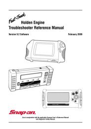
General circuit testing (voltage drop testing)General <str<strong>on</strong>g>Reference</str<strong>on</strong>g>In most cases, measuring the voltage at various points in a circuit will tell you more aboutthe circuit integrity than measuring the circuit resistance (ohms). A good circuit c<strong>on</strong>sists ofthe supply voltage, a load, and a ground. The load should be activated when current passesthrough it. A load is any electrical comp<strong>on</strong>ent, such as a lamp, a motor, a solenoid, or a relay.Most electrical circuits also include a fuse <strong>on</strong> the supply side to protect the load in the eventof a short or power surge. Typically, mechanically-switched circuits, such as headlamps andwiper motors, have a switch <strong>on</strong> the supply side of the load. Electr<strong>on</strong>ically-switched circuitssuch as a TCC solenoid or an EGR solenoid, are usually ground-side switched. Remember,many switches actually energize a relay which, in turn, activates a circuit.To determine if a circuit is good, check the supply voltage to the load, and check the ground.Figure 1 shows you how to test the supply voltage. C<strong>on</strong>nect the positive (+) DVOM leadto pin A of the load, and the negative (-) DVOM lead to chassis ground. With the switchclosed, the DVOM indicates a good supply voltage (13.00 volts) at pin A of the load. Thistypically indicates that the supply side of the circuit is good. It also indicates that the fuseis not blown. If the fuse was blown, the DVOM would indicate zero volts <strong>on</strong> the supply sideof the circuit.BATTERY VOLTAGE(V Batt) SWITCHFUSE HOLDERAMOTOR(LOAD)BGROUNDFigure 1. Good supply voltage.Figure 2 <strong>on</strong> the next page shows you how to test the ground side of the circuit. The DVOMindicates a good ground (0.00 volts) at pin B of the load, with the switch closed. This typicallyindicates that the ground side of the circuit is good. (Most DVOM readings will fluctuate atzero volts; a DVOM reading of 0.03 is quite comm<strong>on</strong>. A ground side reading of 0.10 is anaccepted reading.)Usually, the fastest and easiest way to check a circuit is to start at the load. In general, thereare <strong>on</strong>ly six basic types of electrical problems that can affect automotive electrical circuits:• No supply voltage• An open ground• A voltage drop <strong>on</strong> the supply voltage side • A shorted lead• A voltage drop <strong>on</strong> the ground side• An open loadPAGE 5
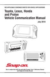
BATTERY VOLTAGE(V Batt) SWITCHFUSE HOLDERAMOTOR(LOAD)BGROUNDNote: Most DVOM readings will fluctuate at zero-volts;a DVOM reading of 0.03 is quite comm<strong>on</strong>. A groundside reading of 0.10 is generally acceptable.Voltage Drop Across The LoadFigure 2. Good ground.In some cases it may be preferable to actually measure the voltage directly across a load.This may be because you suspect a poor c<strong>on</strong>necti<strong>on</strong>, corroded terminals, or a specific openor shorted comp<strong>on</strong>ent, or simply because a known good ground is not near the porti<strong>on</strong> ofthe circuit you are testing. Resistance can be high in l<strong>on</strong>g thin wires, in poor c<strong>on</strong>necti<strong>on</strong>s,and in corroded terminals. Therefore, wires, poor c<strong>on</strong>necti<strong>on</strong>s, and corroded terminals cansometimes “load” a circuit.To measure the voltage drop across a load, c<strong>on</strong>nect the positive (+) DVOM lead to the supplyside of the load, and the negative (-) DVOM lead to the ground side of the load, figure 3. In anormally operating circuit, most of the supplied voltage is dropped across the load. If thereare two or more loads in a circuit, the voltage drop is divided in proporti<strong>on</strong> to the resistanceof each load. That is, the voltage drop across each comp<strong>on</strong>ent should add up to the totalsupply voltage.BATTERY VOLTAGE(V Batt) SWITCHFUSE HOLDERAMOTOR(LOAD)BGROUNDFigure 3. Voltage drop across the load.PAGE 6
Diagnosing Circuit ProblemsTable 1 describes the symptoms, probable causes, and likely soluti<strong>on</strong>s for a circuit that isswitched ON, but not operating properly. For a circuit that is switched OFF, but is still running,use a DVOM to probe between the load and the switch. Always start as close to the switch aspossible. After isolating the problem to a specific segment of the circuit, unhook the circuitat that point to c<strong>on</strong>firm that the circuit stops running. Always test the entire circuit (supplyside and ground side) after fixing a problem.Table 1. Circuit switched ON, but not operating properly. (All DVOM readings are referenced to batteryground, or a good chassis ground, separate from the circuit being tested.)Supply Side Ground Side Probable Cause Likely Soluti<strong>on</strong>V batt 0.00-volts Bad device or c<strong>on</strong>necti<strong>on</strong>s Check for loose or corroded c<strong>on</strong>nector;to deviceif OK, replace comp<strong>on</strong>ent. Always test theentire circuit (supply side and ground side)after fixing a problem.V batt V batt Open ground circuit Use DVOM to probe circuit between groundside of comp<strong>on</strong>ent and ground source.Open circuit is located between adjacenttest points having different readings.Always test the entire circuit (supply sideand ground side) after fixing a problem.0.00-volts 0.00-volts Open supply circuit Use DVOM to backprobe circuit betweensupply side of circuit and the supply source.Open circuit is located between adjacenttest points having different readings. If fuseis open, check for a short to ground insecti<strong>on</strong> of circuit between load side of fuseand supply side of load. Always test theentire circuit (supply side and ground side)after fixing a problem.V batt Greater than High resistance ground Use DVOM to probe circuit between ground0.00-volts, c<strong>on</strong>necti<strong>on</strong> side of comp<strong>on</strong>ent and ground source.less thanHigh resistance circuit is located betweenV battadjacent test points having differentreadings. Always test the entire circuit(supply side and ground side) after fixinga problem.Less than 0.00-volts High resistance power Use DVOM to backprobe circuit betweenV batt, c<strong>on</strong>necti<strong>on</strong> supply side of circuit and supply source.greater thanHigh resistance circuit is located between0.00-voltsadjacent test points having differentreadings. Always test the entire circuit(supply side and ground side) after fixinga problem.Note: Most DVOM readings will fluctuate at zero-volts; a DVOM reading of 0.03 is quite comm<strong>on</strong>. Aground side circuit reading of 0.10 volts is acceptable.PAGE 7
ECU MODULE IDENTIFICATION CODEThis code is sometimes listed in fr<strong>on</strong>t of self test codes. It is for ECU identificati<strong>on</strong> <strong>on</strong>ly anddoes not indicate a fault.TWO DIGIT CODES EA TO EDCODE ID No. ENGINE TRANS CODE ID No. ENGINE TRANS20 3.9 MPEFI MAN A1 4.0 MPEFI AUTO4.0 MPEFI MAN A2 4.0 MPEFI AUTO30 3.9 MPEFI AUTO A3 4.0 MPEFI AUTO4.0 MPEFI AUTO B2 4.0 MPEFI MAN40 3.9 TBI MAN C1 5.0 SEFI AUTO4.0 MPEFI AUTO C2 5.0 SEFI AUTO50 3.9 TBI AUTO D1 5.0 SEFI XR8 MAN4.0 MPEFI AUTO 20 4.0 MPEFI TICKFORD MAN60 3.2 TBI MAN AA 4.0 MPEFI XR6 MAN5.0 SEFI MAN A9 4.0 MPEFI XR6 AUTO70 3.2 TBI AUTO BA 4.0 MPEFI XR6 AUTO5.0 SEFI AUTO B9 4.0 MPEFI XR6 MAN80 5.0 SEFI AUTO C9 5.0 SEFI GT AUTO90 4.0 MPEFI MAN D9 5.0 SEFI GT MANEF MODELTHREE DIGIT CODESEL MODELCODE ID No. ENGINE TRANS CODE ID No. ENGINE TRANS911 4.0 MPEFI MAN 923 4.0 MPEFI AUTO912 4.0 MPEFI AUTO 927 4.0 MPEFI MAN913 4.0 MPEFI AUTO 929 4.0 MPEFI AUTO914 5.0 SEFI XR8 MAN 939 4.0 MPEFI AUTO915 5.0 SEFI AUTO 941 5.0 SEFI AUTO916 4.0 MPEFI XR6 MAN 942 5.0 SEFI XR8 & Police AUTO917 4.0 MPEFI XR6 AUTO 944 4.0 MPEFI XR6 MAN918 4.0 MPEFI XR6 MAN 945 4.0 MPEFI XR6 AUTO919 4.0 MPEFI XR6 AUTO 948 4.0 MPEFI LPG AUTO921 4.0 MPEFI Police AUTO 954 4.0 MPEFI XR6 Police AUTO922 4.0 MPEFI AUTO 958 4.0 MPEFI LPG AUTO924 5.0 SEFI XR8 & Police AUTO 959 5.0 SEFI XR8 MAN926 4.0 MPEFI LPG AUTO932 4.0 MPEFI TICKFORD AUTO933 4.0 MPEFI LPG AUTO950 4.0 MPEFI XR6 Police AUTOPAGE 8
<str<strong>on</strong>g>Ford</str<strong>on</strong>g> <str<strong>on</strong>g>Reference</str<strong>on</strong>g> BulletinsRef. No. Page SubjectF001 11 EA Model 6 cyl throttle body injecti<strong>on</strong> wiring diagram and c<strong>on</strong>nectorsF002 13 EA Model 6 cyl multipoint injecti<strong>on</strong> wiring diagram and c<strong>on</strong>nectorsF003 15 EB Model 6 cyl throttle body injecti<strong>on</strong> wiring diagram and c<strong>on</strong>nectorsF004 17 EB Model 6 cyl multipoint injecti<strong>on</strong> wiring diagram and c<strong>on</strong>nectorsF005 19 EB Model V8 sequential injecti<strong>on</strong> wiring diagram and c<strong>on</strong>nectorsF006 21 EBII/ED Model 6 cyl multipoint injecti<strong>on</strong> wiring diagram and c<strong>on</strong>nectorsF007 23 EBII/ED Model V8 sequential injecti<strong>on</strong> wiring diagram and c<strong>on</strong>nectorsF008 25 EF Model 6 cyl multipoint injecti<strong>on</strong> wiring diagram and c<strong>on</strong>nectorsF009 27 EL Model 6 cyl multipoint injecti<strong>on</strong> wiring diagram and c<strong>on</strong>nectorsF010 29 EF/EL Model V8 sequential injecti<strong>on</strong> wiring diagram and c<strong>on</strong>nectorsF011 31 TFI module resistance testF012 32 Expected oscilloscope waveformsF013 33 Air charge temperature and engine coolant temperature sensorresistance chart and c<strong>on</strong>nector diagramF014 33 EA/EB 6 cyl throttle body injecti<strong>on</strong> throttle body showing base idle screwF015 34 EA to ED 6 cyl multipoint injecti<strong>on</strong> throttle body showing base idle screwF016 35 EA to EL V8 throttle body showing base idle screwF017 36 EF/EL 6 cyl multipoint injecti<strong>on</strong> throttle body showing base idle screwF018 37 EA to ED 6 cyl fuel pressure and volume testingF019 38 EA to ED V8 fuel pressure and volume testingF020 38 EF to EL fuel pressure and volume testingPAGE 9
PLEASE NOTE WIRING DIAGRAM WIRE COLOURS ARE GIVENAT THE ECU AND MAY NOT ALWAYS BE CORRECT DUE TOMANUFACTURING CHANGES IN PRODUCTION. ALSO WIRECOLOURS AT COMPONENTS AND SENSORS MAY NOT BE THESAME AS AT THE ECU PARTICULARLY ON V8 MODELS DUE TOENGINE BEING IMPORTED.ALL CONNECTORS ARE VIEWED LOOKING INTO FACE OFCONNECTION.PAGE 10
F001F001EA Model 6 cyl throttle body injecti<strong>on</strong> wiring diagram10 PK TO A/C SYSTEMLATEPRODUCTIONEARLYPRODUCTION1 Y37 R57 R22 BRN/GRN31 Y/BLUCANISTERPURGE SOLENOIDFUEL PUMPFUEL PUMPRELAYIGNITIONSWITCHEFI POWERRELAY+ -56 BRN36 Y/GRN16 BLA/O21 GRY/WH41 WH/BLU17 WH/BLA48 WH/R6 Y46 BLA/WH47 GRN/BLA45 BLU/Y25 Y/R26 O/BLA7 GRN/Y30 O/BLA20 BLASHIELDEDWIRES TOGROUND5 R24 WH/GRN34 GRN/Y3 WH29 GRN/BLUTOSTARTERCIRCUITMAPSENSORRACTAIRCHARGETEMPSENSOR123456TO TRIP COMPUTER- ------ - -TFIMODULEPK/BLUIGN COILTPSTHROTTLEPOSITIONSENSOR(MANUALONLY)NEUTRAL DRIVECLUTCH SWITCHHEGOFUSETACHOSWITCHISCIDLE SPEEDCONTROLDC MOTORECTENGINECOOLANTTEMPSENSORNEUTRALDRIVESWITCH(AUTO ONLY)TOSPEEDOMETERSELF TESTCONNECTORS------PSPSPOWER STEERINGPRESSURE SWITCHVSSVEHICLESPEED SENSORENGINEECU49 GRY/BLU60 BLA/GRN40 BLA/GRN59 GRN58 BRNA BINJECTORSHEGOO 2SENSORCOLOUR CODE LEGENDBLA - BLACKBLU - BLUEBRN - BROWNGRN - GREENGRY - GREYO - ORANGEPK - PINKPUR - PURPLER - REDV - VIOLETWH - WHITEY - YELLOWENGINEECUCONNECTOR604020O O O O O O O O O OO O O O O O O O O OO O O O O O O O O OO O O O O O O O O OO O O O O O O O O OO O O O O O O O O O1 21 41VIEWED LOOKINGAT THE FACEOF CONNECTIONPAGE 11
F001 & F003A PARTS.F001 EA Model 6 cyl throttle body injecti<strong>on</strong> wiring c<strong>on</strong>nectorsFUSIBLELINK1 1 16IGNITIONSWITCH1POWERRELAY1 576016FUEL PUMPRELAY1 195722VSSVEHICLE SPEEDSENSOR3 99860FUEL PUMPWAGONFUEL PUMPSEDAN19ACTAIR CHARGETEMP SENSOR25ECTENGINE COOLANTTEMP SENSOR7MAPMANIFOLDABSOLUTEPRESSURETPSTHROTTLEPOSITIONSENSOR4619 6060464646 45 262647ISCIDLE SPEED CONTROLDC MOTOR21 41INJ B 58FUELINJECTORSIGNITIONCOIL16 11TFITHICK FILM IGNITIONDISTRIBUTOR5 3 26 124 4657INJ A594HEGOHEATED EXHAUST GASOXYGEN SENSOR60 687PSPSPOWER STEERINGPRESSURE SWITCHCANPCANNISTER PURGESOLENOIDOUTSELF TESTCONNECTORSIN2946 657 31461748PAGE 12
F002 & F004F002EA Model 6 cyl multipoint injecti<strong>on</strong> wiring diagram10 PK TO A/C SYSTEM1 Y/BLA37 R57 R22 BRN/GRN31 Y/BLUCANISTERPURGE SOLENOIDFUEL PUMPFUEL PUMPRELAYIGNITIONSWITCHEFI POWERRELAY+ -56 BRN36 Y/GRN16 BLA/O5 RSHIELDEDWIRES TOGROUNDTOSTARTERCIRCUITR123456- ------ - -TFIMODULEPK/BLUIGN COILHEGOFUSETACHOSELF TESTCONNECTORS------21 GRY/WH17 WH/BLA48 WH/R6 Y46 BLA/WH47 GRN/BLA45 BLU/Y25 Y/R26 O/BLA7 GRN/YMAPSENSORACTAIRCHARGETEMPSENSORTPSTHROTTLEPOSITIONSENSORISCIDLE SPEEDCONTROLVALVEECTENGINECOOLANTTEMPSENSORPSPSPOWER STEERINGPRESSURE SWITCH30 O/BLA34 GRN/Y20 BLA3 WH29 GRN/BLUTO TRIP COMPUTER(MANUALONLY)NEUTRAL DRIVECLUTCH SWITCHSWITCHNEUTRALDRIVESWITCH(AUTO ONLY)TOSPEEDOMETERVSSVEHICLESPEED SENSORENGINEECU49 GRY/BLU60 BLA/GRN40 BLA/GRN59 GRN58 BRN1 5 3 6 2 4INJECTORSHEGOO 2SENSORCOLOUR CODE LEGENDBLA - BLACKBLU - BLUEBRN - BROWNGRN - GREENGRY - GREYO - ORANGEPK - PINKPUR - PURPLER - REDV - VIOLETWH - WHITEY - YELLOWENGINEECUCONNECTOR604020O O O O O O O O O OO O O O O O O O O OO O O O O O O O O OO O O O O O O O O OO O O O O O O O O OO O O O O O O O O O1 21 41VIEWED LOOKINGAT THE FACEOF CONNECTIONPAGE 13
F002 & F004 PARTS.F002EA Model 6 cyl multipoint injecti<strong>on</strong> wiring c<strong>on</strong>nectorsFUSIBLELINK1 1 16IGNITIONSWITCH1POWERRELAY1 571660FUEL PUMPRELAY1 195722VSSVEHICLE SPEEDSENSOR3 99860FUEL PUMPWAGONFUEL PUMPSEDAN19ACTAIR CHARGETEMP SENSOR25ECTENGINE COOLANTTEMP SENSOR7MAPMANIFOLDABSOLUTEPRESSURETPSTHROTTLEPOSITIONSENSOR4619 6060464646 45 262647ISCIDLE SPEED CONTROLVALVE57 21FUEL INJECTORSINJECTOR A INJECTOR B58 59IGNITIONCOIL16 11TFITHICK FILM IGNITIONDISTRIBUTOR5 3 26 157 57INJ 1, 3, 5 INJ 2, 4, 64HEGOHEATED EXHAUST GASOXYGEN SENSOR60 687PSPSPOWER STEERINGPRESSURE SWITCHCANPCANNISTER PURGESOLENOIDOUTSELF TESTCONNECTORSIN2946 657 31461748PAGE 14
F003F003EB Model 6 cyl throttle body injecti<strong>on</strong> wiring diagram10 PK TO A/C SYSTEM1 Y/BLA37 R57 R22 BRN/GRN31 Y/BLUCANISTERPURGE SOLENOIDFUEL PUMPFUEL PUMPRELAYIGNITIONSWITCHEFI POWERRELAY+ -56 BRN36 Y/GRN16 BLA/O21 GRY/WH41 WH/BLU17 WH/BLA48 WH/R6 Y46 BLA/WH47 GRN/BLA45 BLU/Y25 Y/R26 O/BLA7 GRN/Y30 O/BLA20 BLASHIELDEDWIRES TOGROUND5 R24 WH/GRN34 GRN/Y3 WH29 GRN/BLUTOSTARTERCIRCUITMAPSENSORRACTAIRCHARGETEMPSENSOR123456TO TRIP COMPUTER- ------ - -TFIMODULEPK/BLUIGN COILTPSTHROTTLEPOSITIONSENSOR(MANUALONLY)NEUTRAL DRIVECLUTCH SWITCHHEGOFUSETACHOSWITCHISCIDLE SPEEDCONTROLDC MOTORECTENGINECOOLANTTEMPSENSORNEUTRALDRIVESWITCH(AUTO ONLY)TOSPEEDOMETERSELF TESTCONNECTORS------PSPSPOWER STEERINGPRESSURE SWITCHVSSVEHICLESPEED SENSORENGINEECU49 GRY/BLU60 BLA/GRN40 BLA/GRN59 GRN58 BRNA BINJECTORSHEGOO 2SENSORCOLOUR CODE LEGENDBLA - BLACKBLU - BLUEBRN - BROWNGRN - GREENGRY - GREYO - ORANGEPK - PINKPUR - PURPLER - REDV - VIOLETWH - WHITEY - YELLOWENGINEECUCONNECTOR604020O O O O O O O O O OO O O O O O O O O OO O O O O O O O O OO O O O O O O O O OO O O O O O O O O OO O O O O O O O O O1 21 41VIEWED LOOKINGAT THE FACEOF CONNECTIONPAGE 15
F001 & F003A PARTS.F003 EB Model 6 cyl throttle body injecti<strong>on</strong> wiring c<strong>on</strong>nectorsFUSIBLELINK1 1 16IGNITIONSWITCH1POWERRELAY1 576016FUEL PUMPRELAY1 195722VSSVEHICLE SPEEDSENSOR3 99860FUEL PUMPWAGONFUEL PUMPSEDAN19ACTAIR CHARGETEMP SENSOR25ECTENGINE COOLANTTEMP SENSOR7MAPMANIFOLDABSOLUTEPRESSURETPSTHROTTLEPOSITIONSENSOR4619 6060464646 45 262647ISCIDLE SPEED CONTROLDC MOTOR21 41INJ B 58FUELINJECTORSIGNITIONCOIL16 11TFITHICK FILM IGNITIONDISTRIBUTOR5 3 26 124 4657INJ A594HEGOHEATED EXHAUST GASOXYGEN SENSOR60 687PSPSPOWER STEERINGPRESSURE SWITCHCANPCANNISTER PURGESOLENOIDOUTSELF TESTCONNECTORSIN2946 657 31461748PAGE 16
F002 & F004F004EB Model 6 cyl multipoint injecti<strong>on</strong> wiring diagram10 PK TO A/C SYSTEM1 Y/BLA37 R57 R22 BRN/GRN31 Y/BLUCANISTERPURGE SOLENOIDFUEL PUMPFUEL PUMPRELAYIGNITIONSWITCHEFI POWERRELAY+ -56 BRN36 Y/GRN16 BLA/O5 RSHIELDEDWIRES TOGROUNDTOSTARTERCIRCUITR123456- ------ - -TFIMODULEPK/BLUIGN COILHEGOFUSETACHOSELF TESTCONNECTORS------21 GRY/WH17 WH/BLA48 WH/R6 Y46 BLA/WH47 GRN/BLA45 BLU/Y25 Y/R26 O/BLA7 GRN/YMAPSENSORACTAIRCHARGETEMPSENSORTPSTHROTTLEPOSITIONSENSORISCIDLE SPEEDCONTROLVALVEECTENGINECOOLANTTEMPSENSORPSPSPOWER STEERINGPRESSURE SWITCH30 O/BLA34 GRN/Y20 BLA3 WH29 GRN/BLUTO TRIP COMPUTER(MANUALONLY)NEUTRAL DRIVECLUTCH SWITCHSWITCHNEUTRALDRIVESWITCH(AUTO ONLY)TOSPEEDOMETERVSSVEHICLESPEED SENSORENGINEECU49 GRY/BLU60 BLA/GRN40 BLA/GRN59 GRN58 BRN1 5 3 6 2 4INJECTORSHEGOO 2SENSORCOLOUR CODE LEGENDBLA - BLACKBLU - BLUEBRN - BROWNGRN - GREENGRY - GREYO - ORANGEPK - PINKPUR - PURPLER - REDV - VIOLETWH - WHITEY - YELLOWENGINEECUCONNECTOR604020O O O O O O O O O OO O O O O O O O O OO O O O O O O O O OO O O O O O O O O OO O O O O O O O O OO O O O O O O O O O1 21 41VIEWED LOOKINGAT THE FACEOF CONNECTIONPAGE 17
F002 & F004 PARTS.F004EB Model 6 cyl multipoint injecti<strong>on</strong> wiring c<strong>on</strong>nectorsFUSIBLELINK1 1 16IGNITIONSWITCH1POWERRELAY1 571660FUEL PUMPRELAY1 195722VSSVEHICLE SPEEDSENSOR3 99860FUEL PUMPWAGONFUEL PUMPSEDAN19ACTAIR CHARGETEMP SENSOR25ECTENGINE COOLANTTEMP SENSOR7MAPMANIFOLDABSOLUTEPRESSURETPSTHROTTLEPOSITIONSENSOR4619 6060464646 45 262647ISCIDLE SPEED CONTROLVALVE57 21FUEL INJECTORSINJECTOR A INJECTOR B58 59IGNITIONCOIL16 11TFITHICK FILM IGNITIONDISTRIBUTOR5 3 26 157 57INJ 1, 3, 5 INJ 2, 4, 64HEGOHEATED EXHAUST GASOXYGEN SENSOR60 687PSPSPOWER STEERINGPRESSURE SWITCHCANPCANNISTER PURGESOLENOIDOUTSELF TESTCONNECTORSIN2946 657 31461748PAGE 18
F005F005EB Model V8 sequential injecti<strong>on</strong> wiring diagramENGINEECU10 PK/BLU TO A/C SYSTEM1 Y/BLA37 R57 R22 BRN/GRN31 Y/BLU19 BLA/Y56 BRN36 Y/GRNSHIELDEDWIRES TOGROUND16 BLA/O5033BLU/OGRN9 BRN/R21 WH/BLU17 WH/BLA4827WH/RR4647BLA/WHGRN/BLA45 BLU/Y25 Y/R26 O/BLA7 GRN/Y30 O/BLA5 GRN32 R20 BLA6 WH29 GRN/BLU43 BLU/GRN49 GRY/BLU60 BLA/GRN40 BLA/GRN52 BLU42 BRN/Y15 GRN14 BRN/R13 BRN/BLU12 BLU/Y59 GRN58 BRNCANISTERPURGE SOLENOIDTOSTARTERCIRCUITBAPSENSORTO AUTOTRANS ECURACTAIRCHARGETEMPSENSORFUEL PUMP123456- ------ - -TFIMODULEPK/BLUHEGOLH O2SENSORFUEL PUMPRELAYIGN COILTPSTHROTTLEPOSITIONSENSOR(MANUALONLY)NEUTRAL DRIVECLUTCH SWITCH1 2 3 4 5 6 7 8INJECTORSIGNITIONSWITCHHEGOFUSETACHOSWITCHISCHEGORH O2SENSOREFI POWERRELAYMAFMASS AIR FLOW METEREGRACTUATORSOLENOIDIDLE SPEEDCONTROLVALVEECTENGINECOOLANTTEMPSENSORNEUTRALDRIVESWITCH(AUTO ONLY)TOSPEEDOMETERSELF TESTCONNECTORS------+ -EGRVALVEPOSITIONSENSORVSSVEHICLESPEED SENSORCOLOUR CODE LEGENDBLA - BLACKBLU - BLUEBRN - BROWNGRN - GREENGRY - GREYO - ORANGEPK - PINKPUR - PURPLER - REDV - VIOLETWH - WHITEY - YELLOWENGINEECUCONNECTOR604020O O O O O O O O O OO O O O O O O O O OO O O O O O O O O OO O O O O O O O O OO O O O O O O O O OO O O O O O O O O O1 21 41VIEWED LOOKINGAT THE FACEOF CONNECTIONPAGE 19
F005 PARTS.F005EB Model V8 sequential injecti<strong>on</strong> wiring c<strong>on</strong>nectors1FUSIBLELINK16IGNITIONSWITCH1POWERRELAY1 571660FUEL PUMPRELAY1 195722VSSVEHICLE SPEEDSENSOR6 99860FUEL PUMPSWAGON19 60SEDAN19ISCIDLE SPEEDCONTROL VALVE2157ACTAIR CHARGETEMP SENSOR4625ECTENGINE COOLANTTEMP SENSOR467MAFMASS AIR FLOWSENSOR50 579 6026TPSTHROTTLEPOSITIONSENSOR474660EVPEGR VALVEPOSITION SENSOR27 2646EVREGR VALVEREGULATOR SOLENOIDFUEL INJECTORSINJ 1 INJ 2 INJ 3 INJ 458 59 12 1357 57 57 57INJ 5 INJ 6 INJ 7 INJ 814 15 42 52IGNITIONCOIL16 11TFITHICK FILM IGNITIONDISTRIBUTOR5 3 26 1457 3357 5757 57HEATED EXHAUST GASOXYGEN SENSORHEGO LH60 687BAPBAROMETRIC ATMOSPHERICPRESSURE SENSORCANPCANNISTER PURGESOLENOIDOUTSELF TESTCONNECTORSIN43HEGO RH46 45 2657 3146174860 68729PAGE 20
F006F006 EBII/ED Model 6 cyl multipoint injecti<strong>on</strong> wiring diagram27 R12 GRN11 Y/GRN14 Y/R35 GRN/R38 GRN42 BLU/Y51 GRN/BLA52 GRN/WH55 GRN/YTRANSMISSION MODE SWITCHTRANSMISSION MODE INDICATOR LIGHTTO AUTO TRANSMISSIONTO AUTO TRANSMISSIONTO AUTO TRANSMISSIOMTO AUTO TRANSMISSIONTO AUTO TRANSMISSIONTO AUTO TRANSMISSIONTO AUTO TRANSMISSIONTO AUTO TRANSMISSION1 Y/BLA37 R57 R22 BRN/GRN31 Y/BLUCANISTERPURGE SOLENOIDFUEL PUMPFUEL PUMPRELAYIGNITIONSWITCHEFI POWERRELAY+ -56 BRN36 Y/GRN21 GRY/WH48 WH/R17 WH/BLA28 Y46 BLA/WH47 GRN/BLA45 BLU/Y25 Y/R26 O/BLA7 GRN/Y30 O/BLA20 BLASHIELDEDWIRES TOGROUND3 WH29 GRN/BLUTOSTARTERCIRCUITR123456- ------ - -TFIMODULE16 BLA/OPK/BLU5 R4 GRN/V TO SMARTLOCK ECU34 GRN/YMAPSENSORACTAIRCHARGETEMPSENSORTO TRIP COMPUTERIGN COILTPSTHROTTLEPOSITIONSENSOR(MANUALONLY)NEUTRAL DRIVECLUTCH SWITCHHEGOFUSETACHOSWITCHISCIDLE SPEEDCONTROLVALVEECTENGINECOOLANTTEMPSENSORNEUTRALDRIVESWITCH(AUTO ONLY)TOSPEEDOMETERSELF TESTCONNECTORPSPSPOWER STEERINGPRESSURE SWITCHVSSVEHICLESPEED SENSOR49 GRY/BLU60 BLA/GRN40 BLA/GRN59 GRNHEGOO 2SENSORENGINE/TRANSECU58 BRN10 PK/BLU43 BRN/GRN54 O/BLU32 OTO A/C SYSTEMTO A/C SYSTEMTO A/C SYSTEMTO A/C SYSTEM1 5 3 6 2 4INJECTORSCOLOUR CODE LEGENDBLA - BLACKBLU - BLUEBRN - BROWNGRN - GREENGRY - GREYO - ORANGEPK - PINKPUR - PURPLER - REDV - VIOLETWH - WHITEY - YELLOWENGINE/TRANSECUCONNECTOR604020O O O O O O O O O OO O O O O O O O O OO O O O O O O O O OO O O O O O O O O OO O O O O O O O O OO O O O O O O O O O1 21 41VIEWED LOOKINGAT THE FACEOF CONNECTIONPAGE 21
F006 PARTS.F006EBII/ED Model 6 cyl multipoint injecti<strong>on</strong>wiring c<strong>on</strong>nectorsFUSIBLELINK1 1 16IGNITIONSWITCH1POWERRELAY1 571660FUEL PUMPRELAY1 195722VSSVEHICLE SPEEDSENSOR3 99860FUEL PUMPWAGONFUEL PUMPSEDAN19ACTAIR CHARGETEMP SENSOR25ECTENGINE COOLANTTEMP SENSOR7MAPMANIFOLDABSOLUTEPRESSURETPSTHROTTLEPOSITIONSENSOR4619 6060464646 45 262647ISCIDLE SPEED CONTROLVALVE57 21FUEL INJECTORSINJECTOR A INJECTOR BFOR MPFI58 5957 57INJ 1, 3, 5 INJ 2, 4, 6IGNITIONCOIL16 11CANPCANNISTER PURGE SOLENOID57 31TFITHICK FILM IGNITIONDISTRIBUTOR5 3 26 14HEGOHEATED EXHAUST GASOXYGEN SENSOR60 687PSPSPOWER STEERINGPRESSURE SWITCH2028SMARTLOCK ECUXG UTE136122117SELF TESTCONNECTOR48 17 222946 6SMARTLOCK ECUALL OTHER MODELS5 4 18 17 16 15 14 13 12 11 3 2 14610 9 26 25 24 23 22 21 20 19 8 7 6PAGE 22
F007F007EBII/ED Model V8 sequential injecti<strong>on</strong> wiring diagramENGINEECU34 GRN/Y54 O/BLU TO A/C SYSTEM10 PK/BLU TO A/C SYSTEM1 Y/BLA37 R57 R22 BRN/GRN31 Y/BLU19 BLA/Y56 BRN36 Y/GRNSHIELDEDWIRES TOGROUND16 BLA/O5033BLU/OGRN9 BRN/R21 WH/BLU48 WH/R1727WH/BLAR4647BLA/WHGRN/BLA4 GRN/PUR25 Y/R26 O/BLA7 GRN/Y30 O/BLA5 GRN32 R20 BLA6 WH29 GRN/BLU43 BLU/GRN49 GRY/BLU60 BLA/GRN40 BLA/GRN52 BLU42 BRN/Y15 GRN14 BRN/R13 BRN/BLU12 BLU/Y59 GRN58 BRNCANISTERPURGE SOLENOIDTOSTARTERCIRCUITTO TRIP COMPUTERR123456TOSMARTLOCK ACTECUAIRCHARGETEMPSENSORTO AUTOTRANS ECUFUEL PUMP- ------ - -TFIMODULEPK/BLUHEGOLH O2SENSORFUEL PUMPRELAYIGN COILTPSTHROTTLEPOSITIONSENSOR(MANUALONLY)NEUTRAL DRIVECLUTCH SWITCH1 2 3 4 5 6 7 8INJECTORSIGNITIONSWITCHHEGOFUSETACHOSWITCHISCHEGORH O2SENSOREFI POWERRELAYMAFMASS AIR FLOW METEREGRACTUATORSOLENOIDIDLE SPEEDCONTROLVALVEECTENGINECOOLANTTEMPSENSORNEUTRALDRIVESWITCH(AUTO ONLY)TOSPEEDOMETER+ -SELF TESTCONNECTOREGRVALVEPOSITIONSENSORVSSVEHICLESPEED SENSORCOLOUR CODE LEGENDBLA - BLACKBLU - BLUEBRN - BROWNGRN - GREENGRY - GREYO - ORANGEPK - PINKPUR - PURPLER - REDV - VIOLETWH - WHITEY - YELLOWENGINEECUCONNECTOR604020O O O O O O O O O OO O O O O O O O O OO O O O O O O O O OO O O O O O O O O OO O O O O O O O O OO O O O O O O O O O1 21 41VIEWED LOOKINGAT THE FACEOF CONNECTIONPAGE 23
F007 PARTS.F007 EBII/ED Model V8 sequential injecti<strong>on</strong> wiring c<strong>on</strong>nectors1FUSIBLELINK16IGNITIONSWITCH1POWERRELAY1 576016FUEL PUMPRELAY1 195722VSSVEHICLE SPEEDSENSOR6 99860FUEL PUMPSWAGON19 60SEDAN19ISCIDLE SPEEDCONTROL VALVE2157ACTAIR CHARGETEMP SENSOR4625ECTENGINE COOLANTTEMP SENSOR467MAFMASS AIR FLOWSENSOR50 579 6026TPSTHROTTLEPOSITIONSENSOR474660EVPEGR VALVEPOSITION SENSOR27 26FUEL INJECTORSINJ 1 INJ 2 INJ 3 INJ 458 59 12 13IGNITIONCOIL16 11TFITHICK FILM IGNITIONDISTRIBUTOR5 3 246EVREGR VALVEREGULATOR SOLENOID57 57 57 57INJ 5 INJ 6 INJ 7 INJ 814 15 42 526 1457 3357 5757 57HEATED EXHAUST GASOXYGEN SENSORHEGO LH60 687SMARTLOCK ECUCANPCANNISTER PURGESOLENOIDSELF TESTCONNECTOR48 17 2243HEGO RH5 4 18 17 16 15 14 13 12 11 3 2 110 9 26 25 24 23 22 21 20 19 8 7 657 314660 68729PAGE 24
F008F008EF Model 6 cyl multipoint injecti<strong>on</strong> wiring diagramENGINE/TRANSECU17 Y/R42 BLU46 BLU/WH68 BLU28 Y/G29 GRY/BLA79 O/WH96 BLU94 PK/O53 PK/Y81 GRN37 Y1 GRN/V27 O/WH20 GRN/V5571 R97 RWH/BLA80 BRN/GRN67 Y/BLU21 BRN22 GRY85 WH/GRN26 Y/BLA52 Y/R78 Y/WH57 Y/R83 GRY/WH66 WH/R231WH/BLAY91 BLA/WH89 GRN/BLA34 BLU/Y39 BLA/Y90 O/BLA38 GRN/Y64 PK/GRN43 T/O4 GRY/WH25 BLA/GRN58 WH35 GRN/BLUCANISTERPURGE SOLENOIDMAPSENSORTRANSMISSION MODE SWITCHTRANSMISSION MODE INDICATOR LIGHTTO AUTO TRANSMISSIONTO AUTO TRANSMISSIONTO AUTO TRANSMISSIOMTO AUTO TRANSMISSIONTO AUTO TRANSMISSIONTO AUTO TRANSMISSIONTO AUTO TRANSMISSIONIATINTAKEAIR TEMPSENSORTO TRIP COMPUTERFUEL PUMPFUEL PUMPRELAYKNOCKSENSORTPSTHROTTLEPOSITIONSENSOR(MANUALONLY)NEUTRAL DRIVE92 O TO LPG SYSTEM IF FITTED95 Y/WHTO LPG SYSTEM IF FITTED3 GRN/YTO ELECTRONIC COOLING FAN SYSTEMTO ELECTRONIC COOLING FAN SYSTEMTO ELECTRONIC COOLING FAN SYSTEMTO ELECTRONIC COOLING FAN SYSTEMTO AUTO TRANSMISSIONCRANK POSITIONSENSORTO SMARTLOCK ECU10 BLUTO A/C SYSTEM30 WH/GRNTO A/C SYSTEM41 PK/BLUTO A/C SYSTEM69 O/BLUTO A/C SYSTEM86 BRN/GRY93 OTO A/C SYSTEM24 BLA/GRN51 BLA/GRN76 BLA/GRN77 BLA/GRN103 BLA/GRN99 GRN/O73 T/BLA100 BRN/BLU74 BRN/Y101 WH75 T45 PK/BLUTO TACHOINJECTORSTO A/C BLOWER FANCAM POSITIONSENSORBBMBROAD BANDMANIFOLD SOLENOIDCLUTCH SWITCH1 2 3 4 5 6IGNITIONSWITCHHEGOFUSESWITCHISCHEGO2 OSENSOREFI POWERRELAYIDLE SPEEDCONTROLVALVEECTENGINECOOLANTTEMPSENSORNEUTRALDRIVESWITCH(AUTO ONLY)TOSPEEDOMETER163ENGIGN5COILPACK24+ -SELF TESTCONNECTORPSPSPOWER STEERINGPRESSURE SWITCHVSSVEHICLESPEED SENSORCOLOUR CODE LEGENDBLA - BLACKBLU - BLUEBRN - BROWNGRN - GREENGRY - GREYO - ORANGEPK - PINKPUR - PURPLER - REDT - TANV - VIOLETWH - WHITEY - YELLOW- INDICATESHIELDED WIRESTO GROUNDENGINEECUCONNECTOR26 1041 79VIEWED LOOKINGAT THE FACEOF CONNECTIONPAGE 25
F008 F008 EF PARTS. Model 6 cyl multipoint injecti<strong>on</strong> wiring c<strong>on</strong>nectors16IGNITIONSWITCH5555POWERRELAY711677FUEL PUMPRELAY55 197180PSPSPOWER STEERINGPRESSURE SWITCHVSSVEHICLE SPEEDSENSOR7791 3199858FUEL PUMPWAGON77 19FUEL PUMPSEDAN7719IATINTAKE AIRTEMP SENSOR9139ECTENGINE COOLANTTEMP SENSOR3891MAPMANIFOLDABSOLUTEPRESSURE91 34 90TPSTHROTTLEPOSITIONSENSOR918990ISCIDLE SPEEDCONTROL VALVE7183KNOCKSENSOR5791BBMBROAD BANDMANIFOLD SOLENOID7120FUEL INJECTORSNo 1 No 2 No 3757110010171No 4 No 5 No 673747199717171IGNITIONCOIL PACKCRANKSHAFTPOSITIONSENSORCAMSHAFTPOSITIONSENSORCANPCANNISTER PURGESOLENOIDDIAGNOSTICCONNECTOR66 2 801234212291851671 6791HEGOHEATED EXHAUST GASOXYGEN SENSOR77 68710 11 12 13 14 15 16 17 18 19 20BEMBODY ELECTRONIC MODULE INC SMARTLOCKCONNECTOR A CONNECTOR A CONNECTOR B6 7 8 9 10 11 129 10 11 12 13 14 15 16 17 18351 2 3 4 5 6 7 8 91 2 3 4 51 2 3 4 5 6 7 8LOW/MID SERIES VEHICLES HIGH SERIES VEHICLES HIGH SERIES VEHICLESCONNECTOR C22 20 18 16 14 12 10 8 6 4 221 19 17 15 13 11 9 7 5 3 1COMMON ALL VEHICLESPAGE 26
F009F009 EL Model 6 cyl multipoint injecti<strong>on</strong> wiring diagram4 GRN/V39 R33 BLU53 BLU/WH55 Y/G27 GRY/BLA12 O/WH11 BLU14 PK/O35 PK/Y38 GRN42 Y51 O/WH52 GRN/V15 GRN/V1 WH/BLA37 R57 R22 BRN/GRN31 Y/BLUCANISTERPURGE SOLENOIDTO SMARTLOCK ECUTO SPEED SENSITIVE POWER STEERING SSPS (GHIA, FAIRLANE & LTD)TO ELECTRONIC COOLING FAN SYSTEMTO ELECTRONIC COOLING FAN SYSTEMTO AUTO TRANSMISSIONTRANSMISSION MODE SWITCHTRANSMISSION MODE INDICATOR LIGHTTO AUTO TRANSMISSIONTO AUTO TRANSMISSIONTO AUTO TRANSMISSIOMTO AUTO TRANSMISSIONTO AUTO TRANSMISSIONTO AUTO TRANSMISSIONTO AUTO TRANSMISSIONFUEL PUMPFUEL PUMPRELAYBBMBROAD BANDMANIFOLD SOLENOIDIGNITIONSWITCHEFI POWERRELAYENGIGN+ -ENGINE/TRANSECU56 BRN36 Y/GRNSHIELDEDWIRES TOGROUNDENGINE/TRANSECUCONNECTOR604020123456- ------ - -16 O/RPK/BLU5 RKNOCK23 Y/RSENSOR21 GRY/WH48 WH/R17 WH/BLA28 Y46 BLA/WH47 GRN/BLA45 BLU/Y25 BLA/Y26 O/BLA7 GRN/Y30 PK/GRN34 T/O49 GRY/WH20 BLA/GRN3 WH29 GRN/BLU60 BLA/GRN40 BLA/GRN58 TTOSTARTERCIRCUITMAPSENSOR8 O13 BLU/BLA32 Y/WH59 WH10 PK/BLU43 WH/GRN54 O/BLU41 BLU44 BRN/GRYRIATINTAKEAIR TEMPSENSORTO TRIP COMPUTERTO A/C SYSTEMTO A/C SYSTEMTO A/C SYSTEMTO A/C SYSTEMTO A/C BLOWER FANTFIMODULEO O O O O O O O O OO O O O O O O O O OO O O O O O O O O OIGN COILTPSTHROTTLEPOSITIONSENSOR(MANUALONLY)NEUTRAL DRIVETO LPG SYSTEM IF FITTEDTO LPG SYSTEM IF FITTEDTO LPG SYSTEM IF FITTEDCLUTCH SWITCHHEGOFUSETACHOSWITCH1 5 3 6 2 4INJECTORSO O O O O O O O O OISCHEGO2 OSENSORO O O O O O O O O OO O O O O O O O O O1 21 41IDLE SPEEDCONTROLVALVEECTENGINECOOLANTTEMPSENSORNEUTRALDRIVESWITCH(AUTO ONLY)TOSPEEDOMETERCOLOUR CODE LEGENDBLA - BLACKBLU - BLUEBRN - BROWNGRN - GREENGRY - GREYO - ORANGEPK - PINKPUR - PURPLER - REDT - TANV - VIOLETWH - WHITEY - YELLOWVIEWED LOOKINGAT THE FACEOF CONNECTIONSELF TESTCONNECTORPSPSPOWER STEERINGPRESSURE SWITCHVSSVEHICLESPEED SENSORPAGE 27
F009 F009 EL PARTS. Model 6 cyl multipoint injecti<strong>on</strong> wiring c<strong>on</strong>nectors16IGNITIONSWITCH1POWERRELAY1 571660FUEL PUMPRELAY1 195722FUEL INJECTORSCYLINDER 1, 3, 55857CYLINDERS 2, 4 , 659VSSVEHICLE SPEEDSENSOR99860357FUEL PUMPWAGON60 19FUEL PUMPSEDAN6019ACTAIR CHARGETEMP SENSOR4625ECTENGINE COOLANTTEMP SENSOR746MAPMANIFOLDABSOLUTEPRESSURE46 45 26TPSTHROTTLEPOSITIONSENSOR464726ISCIDLE SPEEDCONTROL VALVE5721KNOCKSENSOR2346BBMBROAD BANDMANIFOLD SOLENOID5715IGNITIONCOIL16 11TFITHICK FILM IGNITIONDISTRIBUTOR5 3 26 14SSPSSPEED SENSITIVEPOWER STEERING39PSPSPOWER STEERINGPRESSURE SWITCHCANPCANNISTER PURGESOLENOIDDIAGNOSTICCONNECTOR48 17 221646 657 3146HEGOHEATED EXHAUST GASOXYGEN SENSOR60 6872913 12 11 2 110 9 8 7 6 5 4 326 25 24 15 1423 22 21 20 19 18 17 16BEMBODY ELECTRONIC MODULE INC SMARTLOCK11 2 110 9 8 7 6 5 4 322 13 122120 1918 1716 151410 8 6 4 29 7 5 3 1CONNECTOR A CONNECTOR B CONNECTOR CPAGE 28
F010EF/EL Model V8 sequential injecti<strong>on</strong> wiring diagramF010(EF) 46 BLU/WH43 T/O(EL) 42 R(EF) 42 BLUENGINEECU17 Y/R (EF) BLU (EL)68 BLU (EF) BLU/WH (EL)93 O86 BRN/GRY69 O/BLU30 WH/GRN10 BLU41 PK/BLU55 WH/BLA71 R97 R80 BRN/GRN67 Y/BLU49 BRN50 Y/GRNSHIELDEDWIRES23 O/R4888 BLU/R47 BRN/PK36 T/BLU83 WH/BLU66 WH/R2 WH/BLA65 BRN/PK91 BLA/WH89 GRN/BLA3 GRN/V39 Y/WH90 O/BLA38 GRN/Y64 PK/GRN45 PK/BLU34 T/WH25 BLA/GRN58 WH35 GRN/BLU61 BLU/GRN4 GRY/WH24 BLA/GRN51 BLA/GRN76 BLA/GRN77 BLA/GRN103 BLA/GRN98 BLU72 T/R99 GRN/O73 T/BLA100 BRN/BLU74 BRN/Y101 WH75 TCANISTERPURGE SOLENOIDTOSTARTERCIRCUITTO SMARTLOCKECUTO ELECTRIC COOLING FAN SYSTEM (EF MODEL ONLY)TO TRIP COMPUTER & AUTO TRANS ECU (IF FITTED)TP SPEED SENSITIVE POWER SREERING (S5P5) IF FITTEDTO ELECTRIC COOLING FAN SYSTEM (EF MODEL ONLY)TO A/C SYSTEMTO AUTOTRANS ECURTO ELECTRIC COOLING FAN SYSTEMTO HEATER FAN SYSTEMTO A/C RELAYTO AIR CONDITIONER SYSTEMTO AIR CONDITIONER SYSTEMTO AIR CONDITIONER SYSTEMIATINTAKEAIR TEMPSENSORFUEL PUMP123456- ------ - -TFIMODULEPK/BLUHEGOLH O2SENSORTO ELECTRIC COOLING FAN SYSTEMFUEL PUMPRELAYIGN COILTPSTHROTTLEPOSITIONSENSOR(MANUALONLY)NEUTRAL DRIVECLUTCH SWITCH1 2 3 4 5 6 7 8INJECTORSIGNITIONSWITCHHEGOFUSETACHOSWITCHISCHEGO2 RH OSENSOREFI POWERRELAYMAFMASS AIR FLOW METEREGRACTUATORSOLENOIDIDLE SPEEDCONTROLVALVEECTENGINECOOLANTTEMPSENSORNEUTRALDRIVESWITCH(AUTO ONLY)TOSPEEDOMETERENGIGN+ -SELF TESTCONNECTOREGRVALVEPOSITIONSENSORVSSVEHICLESPEED SENSORCOLOUR CODE LEGENDBLA - BLACKBLU - BLUEBRN - BROWNGRN - GREENGRY - GREYO - ORANGEPK - PINKPUR - PURPLER - REDT - TANV - VIOLETWH - WHITEY - YELLOWENGINEECUCONNECTOR26 1041 79VIEWED LOOKINGAT THE FACEOF CONNECTIONPAGE 29
F010 F010 EF/EL PARTS. Model V8 sequential injecti<strong>on</strong> wiring c<strong>on</strong>nectors16IGNITIONSWITCH5555POWERRELAY711677FUEL PUMPRELAY55 197180MAFMASS AIR FLOWSENSOR88367771VSSVEHICLE SPEEDSENSOR9987758FUEL PUMPWAGON77 19FUEL PUMPSEDAN19IATINTAKE AIRTEMP SENSOR91ECTENGINE COOLANTTEMP SENSOR91FUEL INJECTORSNo 1 No 27510177393871No 3 No 471741007171ISCIDLE SPEEDCONTROL VALVEEVPEGR VALVE POSITIONSENSORTFITHICK FILM IGNITIONDISTRIBUTOR5 3 2No 5 No 6739971836591906 14IGNITION COIL1671No 7 No 872717198714890TPSTHROTTLEPOSITIONSENSOR91EVREGR VALVEREGULATORSOLENOID71 47SSPSSPEED SENSITIVEPOWER STEERING42CANPCANNISTER PURGESOLENOID71 67DIAGNOSTICCONNECTOR66 2 80891691HEATED EXHAUST GASOXYGEN SENSOR77 6876177 68735HEGO LHHEGO RH10 11 12 13 14 15 16 17 18 19 2022 20 18 16 14 12 10 8 6 4 221 19 17 15 13 11 9 7 5 3 1BEMBODY ELECTRONIC MODULE INC SMARTLOCKEF CONNECTOR A EF CONNECTOR A EF CONNECTOR B6 7 8 9 10 11 129 10 11 12 13 14 15 16 17 181 2 3 4 5 6 7 8 91 2 3 4 51 2 3 4 5 6 7 8EF LOW/MID SERIES VEHICLES EF HIGH SERIES VEHICLES EF HIGH SERIES VEHICLESEF CONNECTOR CEF COMMON ALL VEHICLESEL CONNECTOR A EL CONNECTOR B EL CONNECTOR C11 2 110 9 8 7 6 5 4 322 13 12212019 18 171615 1410 8 6 4 29 7 5 3 113 12 11 2 110 9 8 7 6 5 4 323 22 21 20 19 18 17 1626 25 24 15 14EL MODELS EL MODELS EL MODELSPAGE 30
F011TFI module resistance testF011OHMETER52OGND (GROUND)PIP PWR (POWER)PIP-INPIPSPOUTSTARTTFI PWRCOIL-VEING GNDMEASURE BETWEEN RESISTANCETERMINALSGND PIP IN Greater than 500 OhmsPIP PWR PIP IN Less than 2K OhmsPIP PWR TFI PWR Less than 200 OhmsGND IGN GND Less than 2 OhmsPIP IN PIP Less than 200 OhmsPAGE 31
F012Expected oscilloscope waveformsF012Fig 1. SPark OUTput signalFig 2. Profile Igniti<strong>on</strong> Pickup signalFig3. INJector pulse signalFig 4. INJector pulse signalPAGE 32
F013F013Air charge temperature and engine coolanttemperature sensor resistance chartand c<strong>on</strong>nector diagramACTAIR TEMPERATURESENSORECTENGINE COOLANTTEMPERATURE SENSORRESISTANCEACROSSTERMINALSRESISTANCEACROSSTERMINALSF014RESISTANCE AT TEMPERATURE O C58750373002427016150759938432069102030406080100F014EA/EB 6 cyl throttle body injecti<strong>on</strong> throttle bodyshowing base idle screwBASEIDLE SPEEDSCREWTIMING MARKSBALANCESCREWIDLE SPEEDCONTROLDC MOTORPAGE 33
F015EA to ED 6 cyl multipoint injecti<strong>on</strong> throttle bodyshowing base idle screwF015ISCIDLE SPEEDCONTROL VALVETHROTTLEPOSITIONSENSORISCIDLE SPEEDCONTROL VALVEBASE IDLE SPEEDADJUSTING SCREWCABLE SLACKADJUSTINGSCREW, IFLINK FITTEDPAGE 34
F016EA F016 to EL V8 throttle body showing base idle screwEGRVALVE POSITIONSENSOREGRVALVETHROTTLEPOSITIONSENSORIDLE SPEEDCONTROLVALVEBASE IDLE SPEEDSCREW LOCATED ONBOTTOM OF THROTTLEBODYBASE IDLESPEED ADJUSTINGSCREWVIEW LOOKING UNDERTHROTTLE BODYPAGE 35
F017EF/EL 6 cyl multipoint injecti<strong>on</strong> throttle bodyF017showing base idle screwISCIDLE SPEEDCONTROL VALVEBASE IDLESPEED SCREWPAGE 36
1 2 3 4 5 6F018F018 EA to ED 6 cyl fuel pressure and volume testingThrottle body injecti<strong>on</strong>1 2 3 4 5 6PRESSUREGUAGEFUELPRESSUREREGULATORFROM FUEL PUMPIN TANKFUEL RETURNLINE TO TANKMultipoint injecti<strong>on</strong>FUELDELIVERYHOSEFROMFUEL PUMPIN TANKFUEL PRESSUREGAUGERETURN HOSETO FUEL TANKPAGE 37
1 2 3 4 5 61 2 3 4 5 6F019EA to ED V8 fuel pressure and volume testingPOWERSTEERINGRESERVOIRFUEL RETURN LINESUBSTITUTEFUEL LINEHOSEFROMTANKFORVOLUMECHECKINGFUEL SUPPLY LINEPRESSUREGUAGEF020F020EF to EL fuel pressure and volume testingQUICK RELEASETYPE FITTINGSPRESSUREGUAGEFORVOLUMECHECKINGFRONT OFVEHICLEPAGE 38
E&OESNAP-ON TOOLS (AUSTRALIA) PTY LTDABN 55 010 793 683Form ZENGTSFOR92 02/09


![BMW Vehicle Communication Software Manual [1198kb PDF File]](https://img.yumpu.com/41822192/1/190x247/bmw-vehicle-communication-software-manual-1198kb-pdf-file.jpg?quality=85)