Review of the July 2004 Flying Wing workshop - Mat's
Review of the July 2004 Flying Wing workshop - Mat's
Review of the July 2004 Flying Wing workshop - Mat's
- No tags were found...

You also want an ePaper? Increase the reach of your titles
YUMPU automatically turns print PDFs into web optimized ePapers that Google loves.
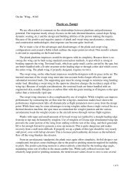
On <strong>the</strong> ’<strong>Wing</strong>...by Bill & Bunny KuhlmanJim Marske has been designingand building full size taillesssailplanes for nearly fifty years,beginning with his XM-1 whichfirst flew in September <strong>of</strong> 1957.The evolution <strong>of</strong> <strong>the</strong> XM-1 to <strong>the</strong>Pioneer II took a number <strong>of</strong> yearsand several prototypes, but <strong>the</strong>evolution <strong>of</strong> Jim’s design did notstop <strong>the</strong>re. The fundamentalplanform has now been used as<strong>the</strong> basis for <strong>the</strong> Pioneer III (avery much updated Pioneer II-D),currently nearing completion, <strong>the</strong>Pioneer IV (15 meter span), and<strong>the</strong> Pioneer V (16.6 meter span),a two place side-by-side trainer.Since Bill attended a <strong>workshop</strong> atMarske <strong>Flying</strong> <strong>Wing</strong>s in 2000,we’ve been keeping abreast <strong>of</strong> <strong>the</strong>happenings at Marske <strong>Flying</strong><strong>Wing</strong>s by visiting <strong>the</strong> web site.Bill noticed a “flying wingdesign” <strong>workshop</strong> announcementon <strong>the</strong> web site early in <strong>2004</strong> andwas seriously consideringattending. Plans were quicklyfirmed up when Mark Nankivilexpressed an interest in attendingas well.The plan was for Bill to fly fromSeattle to St. Louis, and for <strong>the</strong>two to take <strong>of</strong>f on a road tripthrough Muncie (via <strong>the</strong> AMAMuseum) to Marion Ohio, with aside trip to <strong>the</strong> Air force Museumon <strong>the</strong> return. The entire trip wentsmoothly, and some <strong>of</strong> Mark’sphotos from <strong>the</strong> Air ForceMuseum have already appearedin RCSD. (See <strong>the</strong> CG-4A photosin <strong>the</strong> September <strong>2004</strong> issue.)The <strong>workshop</strong> took place over <strong>the</strong>weekend <strong>of</strong> <strong>July</strong> 17-18 at <strong>the</strong>Marske facility near <strong>the</strong> Marionairport. Participants included anaerodynamicist, a couple <strong>of</strong>computer code writers/s<strong>of</strong>twareengineers, a test pilot, and severalo<strong>the</strong>rs with an interest in kitplanes, both as private venturesand with an eye to kit production.Mark and Bill were <strong>the</strong> onlymodelers in attendance.Mat Redsell lead <strong>the</strong> <strong>workshop</strong>and valiantly tried to follow <strong>the</strong>predetermined schedule <strong>of</strong> topicswithin <strong>the</strong> allotted time. As isusual with this sort <strong>of</strong> group, itwas natural for participants tolink one subject to ano<strong>the</strong>r andbecome so entirely engrossed in<strong>the</strong> path <strong>of</strong> conversation that itwas extremely easy to lose track<strong>of</strong> time. Although we nearlyalways gave out groans as Matbrought us back on track, Markand Bill both agreed <strong>the</strong> weekendwas an excellent blend <strong>of</strong> short“lectures” by Mat, Jim, or one <strong>of</strong><strong>the</strong> attendees, and relaxedconversations whererepresentatives <strong>of</strong> <strong>the</strong> variousdisciplines could interact at will.The “icebreaker” was adiscussion focused on <strong>the</strong>misconceptions about taillessaircraft — instability, a tendencyto tumble, complicated controlsystems, etc. Each <strong>of</strong> <strong>the</strong>se wasdispelled in turn by relating <strong>the</strong>experiences <strong>of</strong> Jim and Mat with<strong>the</strong> Pioneer II-D with photo orvideo tape evidence.The Marske planform was <strong>the</strong>npresented as a safe, economicalmethod for achieving exceptionalperformance given its class andconstruction materials. Again,everything was supported withphotos and videos, <strong>the</strong>n Matbrought out <strong>the</strong> spreadsheets.January 2005 1
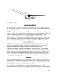
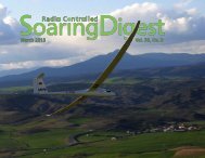
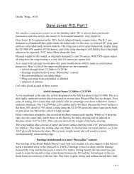
From <strong>the</strong>re, <strong>the</strong> presentationmoved on to <strong>the</strong> actual designprocess. This is <strong>the</strong> one areawhere <strong>the</strong> expertise <strong>of</strong> modelersturned out to be invaluable to <strong>the</strong>ongoing discussion. Compared tothose involved with full sizeaircraft, modelers tend to design,build and fly a much largernumber <strong>of</strong> aircraft over a giventime span. This provides anenormous body <strong>of</strong> first handevidence for what does and doesnot work in practice. And Markand Bill had arrived with a largemental store <strong>of</strong> ideas fromtechnical papers, magazinearticles, and personal experienceregarding tailless planforms.The last portion <strong>of</strong> <strong>the</strong> <strong>workshop</strong>involved <strong>the</strong> future <strong>of</strong> taillessaircraft. Projected improvementsin design and construction, and<strong>the</strong> advances in performancewhich are expected to result,were balanced with <strong>the</strong>acceptance <strong>of</strong> tailless aircraft by<strong>the</strong> public/consumer.Mark and Bill came away from<strong>the</strong> <strong>workshop</strong> with a number <strong>of</strong>ideas for tailless designs,predominantly involvingplanforms with quarter chordlines which are perpendicular to<strong>the</strong> aircraft centerline or slightlyswept forward.As mentioned in prior columns,such a planform, with taper,provides a large arm for <strong>the</strong>elevator function and moves <strong>the</strong>ailerons to a position closer to <strong>the</strong>CG, allowing use <strong>of</strong> differentialwithout adversely affecting pitch.If <strong>the</strong> aspect ratio is held to underten, stall characteristics are quitebenign and <strong>the</strong> Reynolds numbersare larger. Additionally, taillessaircraft <strong>of</strong> this type are quiteeasily constructed, can be verylight, and can be designed to haveminimal drag. All <strong>of</strong> this meansan expanded speed range, ease <strong>of</strong>control, and excellent <strong>the</strong>rmalability.Mat, until recently, had beenflying his Monarch and thrillingin his ability to <strong>the</strong>rmal well invery small areas <strong>of</strong> lift. Whenflying <strong>the</strong> Monarch, <strong>the</strong> pilot isalmost entirely out in <strong>the</strong> open,and subject to feeling <strong>the</strong> airwarm and cool, smelling <strong>the</strong>pollen being lifted by <strong>the</strong>rmals,and having to wipe spider websfrom his or her glasses. Matexplains that flying <strong>the</strong> Monarchis <strong>the</strong> closest thing to actuallybeing a bird that one can imagine.Jim flew his own Monarch atHarris Hill a few years ago andsurprised everyone with a flightMat Redsell takes his Monarch up on auto tow. This launch methodis quite inexpensive. A strain gauge readout visible to <strong>the</strong> drivermakes sure <strong>the</strong> line tension remains consistent.Photo by Bill Kuhlman taken during <strong>the</strong> May 2000 <strong>workshop</strong>.2 R/C Soaring Digest
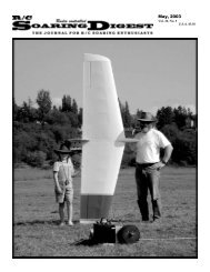
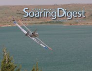
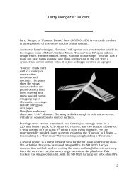
Mike Couts at <strong>the</strong> controls as <strong>the</strong> Pioneer II-D starts its aerotow toaltitude. This ’ship originally belonged to Lloyd Watson who hadpurchased it in nearly complete form from ano<strong>the</strong>r owner. TheMarske <strong>Flying</strong> <strong>Wing</strong>s team rebuilt <strong>the</strong> entire aircraft. The wingsurfaces were contoured to match <strong>the</strong> original airfoil and <strong>the</strong>fuselage underwent some modifications, including addition <strong>of</strong> anose wheel. <strong>Wing</strong> tip extensions were added, increasing <strong>the</strong> wingspan to just over 15 meters. Not readily apparent in this photo are<strong>the</strong> fences which separate <strong>the</strong> inner edge <strong>of</strong> <strong>the</strong> elevator from <strong>the</strong>fuselage fillet. This addittion nearly eliminated <strong>the</strong> separatedturbulent flow at <strong>the</strong> aft end <strong>of</strong> <strong>the</strong> fuslelage. Photo by Bill Kuhlman/in excess <strong>of</strong> four hours from areasonable launch height.Jim and Mat have recentlyexperimented with a moveableCG for <strong>the</strong> Pioneer II-D. Thisopens even more vistas, as trimdrag is substantially reduced. Aten pound weight has beeninstalled, and it travels <strong>the</strong> length<strong>of</strong> <strong>the</strong> fuselage inside a tube,pulled along by a continuouscable attached to a rotary dial.The weight is slid forward forhigh speed cruising, to <strong>the</strong> rearfor <strong>the</strong>rmalling.When Mike Couts landed <strong>the</strong>Pioneer after <strong>the</strong> <strong>workshop</strong>demonstration flight, it seemedlike <strong>the</strong> rollout was extremelylong. Mike later related that once<strong>the</strong> nose wheel touches <strong>the</strong>ground, <strong>the</strong> glider just continuesto travel in a straight line, and it’seasy to run <strong>of</strong>f <strong>the</strong> runway if <strong>the</strong>aircraft is canted on landing dueto a cross-wind. When <strong>the</strong> mainwheel touched <strong>the</strong> ground, Mikehad simply moved <strong>the</strong> weight to<strong>the</strong> extreme rear <strong>of</strong> <strong>the</strong> aircraftand was able to hold <strong>the</strong> nosewheel <strong>of</strong>f <strong>the</strong> ground for anextended run. Rudder authoritywas good enough that he couldsteer <strong>the</strong> aircraft down nearly <strong>the</strong>entire length <strong>of</strong> <strong>the</strong> runway.Was <strong>the</strong> <strong>workshop</strong> worthwhile?Bill and Mark agree <strong>the</strong>y learneda lot from <strong>the</strong> <strong>workshop</strong>,particularly because <strong>of</strong> <strong>the</strong> varieddisciplines involved in <strong>the</strong>frequent discussions both during<strong>the</strong> <strong>workshop</strong> and during breaks.Additionally, watching <strong>the</strong>advanced Pioneer II-D fly was anawesome experience.Mark is currently in <strong>the</strong> laststages <strong>of</strong> designing a TD ’wingwhich he hopes to campaign inlocal contests, and Bill is ready tostart building two competitionaircraft for <strong>the</strong> 2005 Visalia Fallfestival — a two meter and anunlimited.The one o<strong>the</strong>r item which Markand Bill agree on is <strong>the</strong> need forscale models for preliminaryflight testing <strong>of</strong> a new design and<strong>the</strong> desire to construct scalemodels just because it’s so cool tobe flying <strong>the</strong> closest thing to a fullsize aircraft without leaving <strong>the</strong>ground. In fact, Marske <strong>Flying</strong><strong>Wing</strong>s is well on <strong>the</strong> way tobuilding a quarter scale PioneerIV. And a future “On <strong>the</strong>’<strong>Wing</strong>...” column will give details<strong>of</strong> <strong>the</strong> Monarch G, in hopes anR/C Soaring Digest reader willtake on <strong>the</strong> challenge.Until next time...January 2005 3
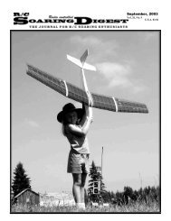
The Pioneer III takes shape at Marske <strong>Flying</strong> <strong>Wing</strong>s in Marion Ohio. This is how<strong>the</strong> airframe appeared in <strong>July</strong> <strong>2004</strong>. Both photos by Mark Nankivil.Left: The fuselage consists <strong>of</strong> a welded steel tube internal frame and a fiberglassshell. The canopy will be hinged from <strong>the</strong> front. When <strong>the</strong> photo was taken, <strong>the</strong>instrument panel was cut out and in place. The rudder was constructed but wasnot attached. As is in keeping with what we have seen as a trend, <strong>the</strong> airfoil hasminimal reflex and <strong>the</strong> pitching moment is only slightly positive.Right: The wings are resting in plywood cradles, leading edge down. Jim Marske’s Monarch wings serve as a backdrop. Notice <strong>the</strong> wing tips carry<strong>the</strong> same elliptical leading edge planform as <strong>the</strong> new tips which have been installed on <strong>the</strong> Pioneer II-D. The ailerons are fabricated but notisntalled as yet. The aileron and air brake pushrods are in evidence. The ribs are specially corrugated fiberglass with lightening holes cut out. Thefabrication <strong>of</strong> <strong>the</strong> Pioneer III owes a lot to a prior building project, an essentially all carbon Monarch. The weight savings and additional strengthmade a big impression on <strong>the</strong> team, and a good portion <strong>of</strong> <strong>the</strong> technology was transferred to <strong>the</strong> fiberglass composite Pioneer II design.Opposite page: The highly modified Pioneer II-D on tow over <strong>the</strong> Marion airport. The Pioneer behaves in excellent fashion when using <strong>the</strong> bridlesystem. Positioning relative to <strong>the</strong> tow aircraft wake is not critical. Photo by Mark Nankivil.Page 30: Mike Couts brings <strong>the</strong> Pioneer II-D in for a smooth landing. Photo by Bill Kuhlman4 R/C Soaring Digest
January 2005 5
6 R/C Soaring Digest