Larry Haig's Minibat - Radio Controlled Soaring Digest
Larry Haig's Minibat - Radio Controlled Soaring Digest
Larry Haig's Minibat - Radio Controlled Soaring Digest
- No tags were found...

Create successful ePaper yourself
Turn your PDF publications into a flip-book with our unique Google optimized e-Paper software.
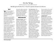
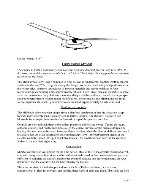
On the ’Wing... #157<strong>Larry</strong> Haig’s <strong>Minibat</strong>The chance to build a reasonably sized 1/2 scale sailplane does not present itself very often. Inthis case, the model wing span would be just 12.5 feet. That’s right, the wing panels turn out to beless than six feet long!The <strong>Minibat</strong> was <strong>Larry</strong> Haig’s response to what he saw as fundamental problems within generalaviation in the late ’70’s. His goals during the design process included safety and performance atthe lowest price, achieved through use of modern materials and recent revisions to FAAregulations; quick building time, approximately 40 to 80 hours; small size and an ability to serveas an inexpensive teaching platform; a modular design which could be expanded to a larger spanand better performance without major modifications. Unfortunately, the <strong>Minibat</strong> did not fulfillsafety requirements, and kit production was terminated. Approximately 55 kits were sold.Planform and controlsThe <strong>Minibat</strong> is also somewhat unique from a planform standpoint in that the wings are sweptforward more severely than is usually seen in tailless aircraft. Jim Marske’s Pioneer II andMonarch, for example, have much less forward sweep of the quarter chord line.Controls are conventional, despite the tailless planform and forward sweep. Central elevators,outboard ailerons, and rudder encompass all of the control surfaces of the original design. Forlanding, the ailerons can be raised into a spoileron position, while the elevator deflects downwardto act as a flap. As of an information bulletin dated April 1981, the outboard ten inches of theelevator could be turned into split panel dive brakes. This modification is noted in the included3-view in the top view, right wing.Construction<strong>Minibat</strong> construction was unique for the time period. Most of the 18 major parts consist of a PVCcore with fiberglass on both sides and formed in a female mold. A few dozen hardware parts aresufficient to complete the aircraft. Despite the extent of molding and preformed parts, the FAAdetermined that the aircraft is 64.5% fabricated by the builder.The wing consists of molded upper and lower shells of E-glass and foam, a spar usingunidirectional S-glass for the caps, and molded shear webs of glass and foam. The shells are held1 of 7
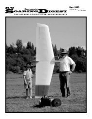
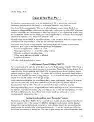
Optional split dive brake Haig <strong>Minibat</strong>Span 25 ft.Length 9.33 ft.Height 5 ft.Wing area 65 ft. 2Airfoil LiebeckWeight, empty 105 lbs.Weight, max. 325 lbs.Load limit 6.0 G’s2 of 7
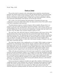
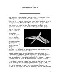
together at the leading edge by J-joint, and at the trailing edge by the molded rear spar. Theelevators and ailerons are made from molded glass upper and lower surfaces over glass and foamribs. The wing halves attach internally at the centerline with pins. Additional wing panels of aboutfour foot length became available to increase the wing span and decrease the wing loading. Theseextensions substantially improved gliding performance.The fuselage is built in the same way as the wings, except there is no spar cap. The outer skincarries the bending loads and the inner skin carries the torsional loads. Reinforcement is providedin the area of the landing gear, tail skid, etc. Besides a J-joint on the outside, the fuselage is tiedtogether on the inside by the seat, armrests and keel.The fin and rudder are constructed like the ailerons and elevators — glass skins are placed overfoam ribs.AirfoilPerhaps the most problematic component of the <strong>Minibat</strong> is the airfoil. A Liebeck section(maximum camber at 20% chord, camber = 5.5%, thickness = 14.5%) was used in an effort toachieve a high coefficient of lift. The Liebeck airfoil was one of the first computer-designedsections, and the code at that time was not reliable. It was predicted that the section would achievea maximum coefficient of lift of at least 1.4 while not having the excessive drag of other high liftsections. Evaluating the Liebeck section with modern computer codes, the Liebeck section doesnot live up to its expectations.• The upper surface does not behave well at Reynolds numbers below three million. A goodsailplane section should be good down to Re = 500K or lower, depending on the local wing chord.The <strong>Minibat</strong> mean chord is 30 inches, and the Reynolds number in slow flight is around onemillion. The wing tips just cannot produce enough lift, and the reaction of the pilot is to feed inmore up elevator. Up elevator produces a large down force, counteracting the lift generated by thewing. Jim Marske predicted that the maximum coefficient of lift of about 0.8 under theseconditions, just 60% of the predicted value.• The bulbous protrusion on the lower surface near the leading edge causes a large amount of dragat high speed. As the angle of attack decreases, this area acts as a lower surface spoiler. Poor uppersurface boundary layer control at low speeds and this lower leading edge protrusion which causesexceptional drag at high speed severely limit the speed range of this section.• Because of the upper surface behavior at low Reynolds numbers, the ailerons on the <strong>Minibat</strong> donot start operating until the aircraft has nearly reached flying speed.• The Liebeck section is not so stable as had been originally thought. In fact, some amount of upelevator trim is required for stable flight. This is not a problem in the <strong>Minibat</strong>, as the elevator islarge, but it is something to keep in mind.Since the Liebeck section performs so poorly on full size aircraft, its performance on a model,even at half size, can be easily predicted to be abysmal. We’ve looked through our collection ofairfoils and found what we believe to be a suitable replacement.Dave Jones was a prolific designer of airfoils for use on plank planforms. Rather than usesophisticated airfoil design programs, Dave utilized relatively simple mathematical formulae to3 of 7
0.20.10-0.10.2Liebeck0.1 0.2 0.3 0.4 0.5 0.6 0.7 0.8 0.9 10.10-0.10.2CJ-21509>240120.10-0.10.2CJ-21509>240140.10-0.10.2CJ-21509>250120.10-0.1CJ-21509>250144 of 7
define camber lines and surface contours. His technique was much like the old NACA 4-digit and5-digit methodologies and the resulting airfoils are turbulent flow sections. This is exactly what isneeded for modeling purposes.One of Dave’s last sections was his CJ-21509 (maximum camber at 20% chord, camber = 1.5%,thickness = 9%). Note that the maximum camber point of the CJ-21509 exactly matches themaximum camber point of the Liebeck airfoil. By increasing the camber of the CJ-21509 to 5%,that parameter can be made roughly the same as the Liebeck. We remain somewhat leery ofincreasing the thickness to 14%. For this reason we’ve plotted other modifications of theCJ-21509 with variations of camber (4% and 5%) and thickness (12% and 14%).We very much recommend that the builder construct a primitive all foam wing and ballast it tomatch the anticipated wing loading of the completed scale model. A free flight prototype would befine. This is the only way to determine if the chosen airfoil will actually work well at the scalemodel Reynolds number.IdiosyncrasiesDuring ROG takeoff, whether by winch or aerotow, there are pronounced pitching momentswhich require compensation. When level on the ground, the CG is below the wing and directlyover the main wheel. While standing still, nose down and ready for takeoff, the CG is in front ofthe wheel. This is because the CG is well above the axle. The elevator and wing reflex areproducing no down force at the rear. As the takeoff roll begins and the air speed increases, theforces generated by the elevator and airfoil reflex increase with the square of the speed. Theaircraft starts to rotate once these aerodynamic forces are great enough, and the CG moves back inrelation to the wheel. As the CG moves over and past the wheel axle, the aircraft is pitched up byboth aerodynamic and mass forces. The greater the upward rotation angle, the more the aircraftwill want to rear back even further.It is therefore possible to lift off the ground at a speed less than the minimal flying speed. Thewing is fully stalled under this condition, the aircraft is not controllable, and a crash is nearlyalways inevitable. Two fatal <strong>Minibat</strong> accidents can most probably be attributed to this behavior.Jim Marske reports, “As I understand it, both accidents occurred during the takeoff run and thegliders cartwheeled down the runway. One wing struck the ground causing a groundloop.”It is imperative that the nose be kept down until flying speed is reached. Once at flying speed andin the air, the location of the CG is below the wing, so the aircraft is self-stabilizing in this regard.The canopy seal must be carefully watched. Air leaks in this area severely degrade performance.Full size flight experiencesTwo flight experiences, while rather harrowing, point out both positive and negative aspects of the<strong>Minibat</strong> design. The first episode, as told by Jim Marske, appeared on the nurflugel e-mail listwhile we were researching this column:“To clear up some mystery concerning the <strong>Minibat</strong> at Elmira, New York back inthe ’80’s. We had a meeting of the U.S. Sailplane Homebuilders group. AlBackstrom, <strong>Larry</strong> Haig and myself gave presentations on flying wings. Just as Icompleted my presentation on the Monarch and Pioneer 2, I was told that <strong>Larry</strong>5 of 7
was about to auto tow his <strong>Minibat</strong> down the Harris Hill runway. If you are notfamiliar with this airstrip, it is about 1,800 feet long with a considerable dropoff ateach end. The <strong>Minibat</strong>, even though it was small and light, it had a small wing alsowhich resulted in a fairly high wing loading. So takeoff speed was quite high andrequired a lengthy run just to get the glider into the air.“Just before my presentation <strong>Larry</strong> told me that one of his elevator bellcrankbrackets had come off. He decided to anchor the bracket with a pair of vise grips (acam lock pliers). Well during the bouncy takeoff the vise grip pliers let go and theyoung pilot was left without any elevator control. The <strong>Minibat</strong> proceeded to climbvery steeply to about 200 feet (65m) where the pilot released. The nose high gliderstalled and dropped vertically for the ground. The pilot, being a hang glider pilot aswell, shifted his weight as far back as he could to effect a recovery - whichfortunately worked. The <strong>Minibat</strong> rounded out just short of the ground andskimmed the runway. The pilot threw his weight forward to keep the glider on theground and stopped just before he slid off the edge of the steep hill. Only the graceof God and his hang gliding experience saved him.“An amusing ending to the story... One fellow was expounding on how dangerousflying wings were as unstable and uncontrollable. I interrupted and asked him justwhat would he have done if he were in a tailed glider and the elevator control didnot respond. I added that if he had been flying anything other than a flying wingunder those circumstances he surely would have been killed. The short coupling ofa flying wing and the rather narrow c.g. range made for a responsive to weight shiftpitch control.”Mat Redsell’s experience was nearly fatal as well. For some reason the CG was misplaced duringpreflight and was too far forward, and this lead to a rather severe dive upon release from the towline. Elevator deflection was not sufficient to correct the situation, so Mat tried shifting back in theseat, much like <strong>Larry</strong> Haig had done at Elmira, but to no avail. In desperation, he folded his kneescloser to his body. This moved the CG far enough aft that the aircraft was controllable in pitch, butthe rudder was free to deflect on its own and it simply followed the oncoming airflow.In contrast to a swept back wing, a forward swept wing is directionally unstable. As soon as heremoved his feet from the pedals, the <strong>Minibat</strong> started yawing. The resulting side slip drasticallyreduced the glide ratio, and stretching the glide to achieve a landing site was next to impossible.When he put his feet back on the pedals to reduce the side slip, the <strong>Minibat</strong> went into a dive. Witha landing site in view, Mat set up an approach. At that point, the <strong>Minibat</strong> went into a side slip andthe canopy blew open. Mat somehow managed to get the canopy closed and make a “successful”landing.ConclusionDespite the relatively poor, unpredictable performance and safety concerns of the full size<strong>Minibat</strong>, it should make a very good scale model. In a model, the CG will not move, controlsurfaces will maintain direct connections to driving servos, and human life is not at stake. Nomatter the airfoil chosen or the scale of the model, keeping the weight down will be the primaryfactor influencing performance. Lower weight equates to lower flying speed and more rapid6 of 7
esponse to control inputs. Additionally, a model at half scale is reasonably sized and would beeasy to detail.Readers wanting coordinate tables for the airfoils mentioned in this month’s column need onlysend a request to us at either our post office box or e-mail address. Suggestions for other viableairfoils are especially wanted.We would appreciate hearing from anyone contemplating construction of a scale rendition of thisaircraft. As usual, we can be reached at P.O. Box 975, Olalla WA 98359-0975, or by e-mail at.ReferencesDevelopments information bulletin. GLA, Inc. April 15, 1981.Jones, Dave. Personal correspondence, December 1989.Hardy, Michael. Gliders and sailplanes of the world. Ian Allan Ltd. London, 1982.Johnson, Dave. MacFoil 1.5. , or throughthe “plotters and helpers” page on the B 2 Streamlines web site.Marske, Jim. Evaluation of the <strong>Minibat</strong>/Liebeck airfoil. Sailplane Homebuilders Association.May 1992. —. Electronic correspondence, February 2002.<strong>Minibat</strong> construction manual. GLA, Inc. Circa 1980.<strong>Minibat</strong> brochure (two pages, folded). GLA, Inc. Circa 1980.<strong>Minibat</strong> brochure (four pages). GLA, Inc. Circa 1980.<strong>Minibat</strong> complete information pack. GLA, Inc. Circa 1980.Redsell, Mat. Personal interview of May 2000, and electronic correspondence, January andFebruary 2002.7 of 7