160 Plank vs Sweptcomplete.FM5 - Radio Controlled Soaring Digest
160 Plank vs Sweptcomplete.FM5 - Radio Controlled Soaring Digest
160 Plank vs Sweptcomplete.FM5 - Radio Controlled Soaring Digest

You also want an ePaper? Increase the reach of your titles
YUMPU automatically turns print PDFs into web optimized ePapers that Google loves.
decades old. Reducing the reflex lowers drag and increases the maximum coefficient of lift.Because the wing is not swept, the air flow tends to remain parallel to the aircraft centerline.Swept wings obtain their stability through aerodynamic wing twist. Depending on theairfoil(s) used, some amount of geometric twist may be required. As can be easily imagined,twisting the wing is a necessary evil — it’s needed for pitch stability, but increases drag duringmost flight regimes.Aerodynamic twist is related directly to some design coefficient of lift. As an example, if thewing twist is set up to provide the stability and coefficient of lift required for thermal flight, highspeed flight will suffer. Large amounts of down elevator will be required to overcome the effectsof the built in washout. This cannot in any way be considered to be aerodynamically “clean.” Dragthus tends to be minimal around some single predetermined design point.Airfoil design for swept wings is challenging as well. While the pitching moment constraint isremoved, an airfoil for use on a swept wing must be able to handle some amount of cross-spanflow. Airfoils designed using two dimensional flow often fail to meet expectations once sweep isapplied. The three-dimensional flow induced by sweep is very much different than the twodimensionalflow which is assumed by the designer and the computer software used.Swept wings may also be able to take advantage of “induced thrust.” Briefly stated, sweeptends to progressively increase the effective angle of attack of outer portions of the wing. Near thewing tips, where the induced upwash is greatest, the lift and drag vectors are rotated forward inrelation to the flight path. To maintain a constant effective angle of attack across the span, someamount of washout is needed. and it is possible to produce some small amount of thrust in theouter region of the wing.But flight is more than simply going forward in a straight line. We want to make sure we cancontrol the aircraft in all three axes — pitch, roll, and yaw — so that we can take off, travel fromone area of lift to another, core any thermals we run into, and land safely.In a conventional tailed aircraft, pitch is handled by the elevator which is mounted on a longarm (the fuselage) well behind the CG. A similar arm is easily applied to a swept wing design bymaking sure the sweep is sufficient to place the elevator some distance behind the CG. The plankplanform is somewhat more limited when it comes to achieving an adequate elevator arm.There are two generalized means of obtaining the required arm within the plank planform: Ifthe planform is of relatively low aspect ratio, obtaining the arm is not too difficult. The elevatorsmay be placed outboard where they can influence the effective angle of attack of the outer portionof the wing. With the elevators deflected upward, the wing has some amount of effective washout,inhibiting tip stall. Dave Jones’ Blackbird 2M serves as an example of this design methodology.As the planform tends to higher aspect ratios, this simple trailing edge placement becomes lesseffective. The usual way of handling this difficulty is to enlarge the local chord near the wing rootso the elevator can be moved inboard and thus further aft.It should be noted that elevator deflection on a plank planform always works against thedesired coefficient of lift. That is, as the elevator is deflected upward to force the wing to a greaterangle of attack, it produces a downforce which to some extent counteracts the generated lift.Similarly, it acts as a flap and produces an increase in lift as it is deflected downward to force thewing to a lower angle of attack.2 of 8
Aileron function is a bit more problematic for swept wing aircraft than for planks, but thereare also some tantalizing possibilities. Adverse yaw is the major problem involved in use ofailerons. In conventional aircraft, adverse yaw is compensated for by aileron differential — theaileron moves further upward than downward — and judicious use of rudder. This is not possibleon the swept wing because of the aft location of the aileron on the wing. The upward movingaileron, with greater deflection, will always tend to pitch the aircraft upward. There are somerather complicated ways of overcoming this tendency, but these involve either some sort ofauxiliary control surface actuated through a mixing function or a special twist and liftdistributions.For a plank with a high aspect ratio tapered planform and a central elevator acting through alarge local chord, like the PN9f or Pioneer II, the outboard ailerons are so close to the CG that anydifferential has no effect on pitch at all. Some method of inhibiting adverse yaw, such as Frisetypecontrol surfaces, may be necessary on a plank with a lower aspect ratio.A single central vertical fin and rudder can be used quite effectively on a plank planform.Proper contouring of the wing-fuselage junction will normally provide a protrusion behind thewing on which this flying surface can be mounted. If there is no fuselage at all, a lightweightboom can be used. It’s important to get a sufficient arm for the fin and rudder to work through.Sweeping the surface rearward can be used to move the aerodynamic center of the flight surfacefurther aft, but it should be noted that a swept hinge line will affect the aircraft in pitch. Someamount of downward lift will be generated each time the rudder is deflected. A swept backvertical fin alone can be used very effectively on designs which do not require a rudder. Thestatements above hold true for swept wings as well.Flaps are always an interesting proposition on tailless aircraft. Conventional tailed aircraft canreadily handle all sorts of flap deflection. That’s because the elevator is mounted on a generousarm, and as long as it’s out of the wing wake, it has a lot of control over the aircraft pitch angleand hence the wing angle of attack. Tailless aircraft, whether swept wing or plank, have a shorterelevator arm. This limits the amount of control over pitch that the elevator has, but controlproblems usually do not arise because of the inherent low moment of inertia. As flaps aredeflected, however, large moments can be generated which cannot be acceptably controlled. It’simportant to formulate the flap size, shape and placement such that deflection does not produceadverse pitching moments.For a plank, flaps of about five percent of the total wing area can usually be mounted such thattheir hinge is at 40% of the local chord. Such a placement minimizes any pitching tendency as theflaps are deflected. Deflection angles of 45 degrees are sufficient. It should be noted that flaps ofthis type are not to be used to improve thermal performance, as the increased lift is far outweighedby the tremendous amounts of drag produced. Such flaps can, however, be used to increase theheight achieved on a winch launch and to effectively control the glide path during landingapproaches.Flaps on swept wings can be used as a means of glide path control and to improve boththermal and high speed performance. Again, placement is an issue, as pitch control should not beadversely affected. Flaps for swept wings should be placed at the trailing edge, but theirplacement along the span is not easily determined. Too far inward and the wing will tend to pitchupward. Too far outboard and flap deflection will force the nose down. Overall size and localchord have an influence as well. Ideally, inner flaps should be deflected downward some small3 of 8
amount while thermalling. The outboard elevons should also be deflected downward tocompensate, thus increasing the generated lift across the entire span. If the root section has anegative (nose down) pitching moment, deflecting the flaps upward by a very few degrees willremove the camber at the rear of the wing, reducing the local coefficient of lift and increasing theflight speed.Inertia in pitch is the one characteristic which we have difficulties evaluating. Our thoughts atthis time are that inertia in pitch is one of those “eye of the beholder” items. Pilots used to flyingconventional tailed aircraft, which have a large amount of inertia in pitch, are initiallyuncomfortable with the relative lack of inertia demonstrated by well designed planks and someswept wing planforms. For full size aircraft, like Jim Marske’s Pioneer II and Monarch, lack ofinertia in pitch gives a more comfortable ride in turbulence. The aircraft reacts quickly todifferences in angle of attack and tends to fly through turbulence by aligning itself with themovement of the local air mass. Tailed aircraft in similar situations tend to bounce up and down.Swept wings tend to react in a way which is somewhere between the two.Some of those who contemplate flying a plank are quite concerned about the lack of overalllength and are worried that they will not be able to see the changes in pitch which allow them tomonitor the performance of their tailed aircraft. After a few flights with a plank, however, theydon’t miss that piece of feedback at all. It becomes “normal” to let the aircraft seek its ownattitude and to control its speed using elevator stick position rather than reacting to perceivedfuselage alignment. The same flying method becomes second nature when steering a swept wingaround the sky.From all of the above, it appears a plank would be the choice of the designer looking for anairframe which can be relatively easily formulated and constructed without resorting tocomposites. <strong>Plank</strong> performance can be exceptional, particularly within thermal duration tasks, andcontrol systems are essentially similar to those of conventional tailed aircraft.A swept wing, while it does pose several unique problems so far as design and construction,certainly has the potential for greater performance in all flight regimes. Although control systemsfor swept wings can be quite complicated, with numerous control surface mixes being the norm, itis possible to tailor the lift distribution across the entire span, greatly increasing efficiency whilemaneuvering. Additionally, the effective dihedral of swept wings varies in direct proportion to thecoefficient of lift, making them very stable in thermals.In the end, it would seem that the designer who is performance driven may be more willing toexpend large amounts of design time for the potential significant performance improvementsavailable from a swept wing. The question as to whether that time and effort is worthwhile,however, is never known until the aircraft is flown.While we most likely haven’t solved any problems, or defined the specific direction a designershould take in producing an airframe, we hope this treatise has provided some useful informationand perhaps initiated some new lines of thought within the minds of readers.Future “On the ’Wing...” columns will cover two topics related specifically to swept wings —wing twist distribution schemes and “induced thrust.” Perhaps an exploration of these topics willentice a few fence sitters to more intensely investigate the rather unique potential of swept wingplanforms.4 of 8
ReferencesJones, Dave. Personal correspondence on installing and using flaps on planks. September 21,1984.Kuhlman, Bill & Bunny. Akaflieg Braunschweig’s SB13 “Arcus,” an update. RC <strong>Soaring</strong> <strong>Digest</strong>.April 1994.—. CO8. RC <strong>Soaring</strong> <strong>Digest</strong>. May and June 1998.—. Six flap control systems. RC <strong>Soaring</strong> <strong>Digest</strong>. July 1995.—. Swept wings and effective dihedral. RC <strong>Soaring</strong> <strong>Digest</strong>. January through April 2000.Marske, Jim. Experiment in flying wing sailplanes. Jim Marske, 1970.—. Pioneer II pamphlet. Jim Marske, circa 1987.Nurflugel e-mail list. Swept back wings <strong>vs</strong>. Marske wings, 13 May through 19 May 1999.Contributions by Al Bowers, Anton Lawrence, Gregg MacPherson, Andrè Luiz Martins, MatRedsell, and others. Paff, Dieter. PN9 and PN9f. The White Sheet, Sean Walbank, editor. February/March 1982.5 of 8
+<strong>Plank</strong>• no twist• basic structure• aileron differential possible• airflow remains parallel to centerline• conventional control system• flaps possible, but see belowSwept• airfoil design has few constraints• substantial elevator arm• winglets improve tip flow• fuselage behind wing leading edge• flaps possible, but see below• can take advantage of “induced thrust”neutral • low inertia in pitch • higher inertia in pitch–• airfoil design limited by C m• increased drag due to reflex• elevator arm relatively short• elevator deflection works against C L• flap effects are limited• fuselage forward of wing leading edge• winglets may harm stall characteristics• required twist increases drag• complicated structure• aileron differential affects pitch• cross-span airflow• winglets work best at one speed• non-conventional control system• flaps difficult to size and positionJim Marske’s Pioneer II-D. An example of a full size plank with taper and an enlarged wing rootchord which allows the elevator to be placed more rearward. Note also the swept back vertical finand rudder which gives a slightly longer arm. Span is 13 meters.6 of 8
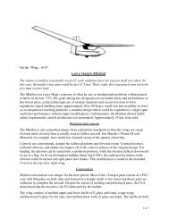
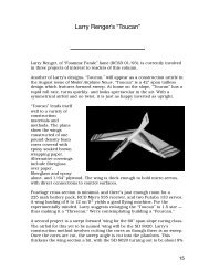
Dieter Paff’s PN9f. This is an RC model based on a preliminary design for a full size sailplane.The wing span is just over three meters.Dave Jones’ Blackbird 2M. The Blackbird 2M is a low aspect ratio plank which uses elevons only.The outboard elevons put effective washout in the wing tips during thermalling. Flaps hinged at40% chord have been used successfully on this model.7 of 8
Akaflieg Braunschweig’s SB 13 Arcus. Constructed by a group of students in Germany, the Arcusfollows the Standard Class rules — 15 meter span, no flaps. Air brakes are used for glide pathcontrol. Note there are two elevon surfaces per side. The spars meet at the fuselage centerperpendicular to the centerline, then curve back roughly following the wing sweep and continuingup the winglet. The spars are monolithic structures of carbon fiber. This airplane was a real handfulto fly until wing fences were installed.Hans-Jürgen Unverferth’s CO8. This is one of the latter in a series of tailless aircraft designed by aGerman team headed by Hans-Jürgen Unverferth. CO8 uses elevons and flaps on a relatively highaspect ratio wing having a span of 2.6 meters.8 of 8