Of for the safe erection and use of scaffolding
Of for the safe erection and use of scaffolding
Of for the safe erection and use of scaffolding
- No tags were found...

Create successful ePaper yourself
Turn your PDF publications into a flip-book with our unique Google optimized e-Paper software.
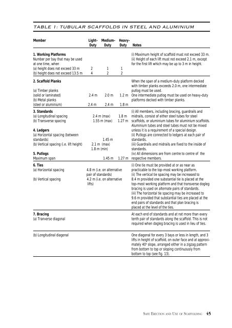
TABLE 1: TUBULAR SCAFFOLDS IN STEEL AND ALUMINIUMMember Light- Medium- Heavy-Duty Duty Duty Notes1. Working Plat<strong>for</strong>ms (i) Maximum height <strong>of</strong> scaffold must not exceed 33 m.Number per bay that may be <strong>use</strong>d(ii) Height <strong>of</strong> each lift must not exceed 2.1 m, exceptat one time, when<strong>for</strong> <strong>the</strong> first lift which may be up to 3 m in height.(a) height does not exceed 33 m 2 1 1(b) height does not exceed 13.5 m 4 2 22. Scaffold Planks When <strong>the</strong> span <strong>of</strong> a medium-duty plat<strong>for</strong>m decked ...with timber planks exceeds 2.0 m, one intermediate(a) Timber planksputlog must be <strong>use</strong>d.(solid or laminated) 2.4 m 2.0 m 1.2 m One intermediate putlog must be <strong>use</strong>d on heavy-duty(b) Metal planksplat<strong>for</strong>ms decked with timber planks.(steel or aluminium) 2.4 m 2.4 m 1.8 m3. St<strong>and</strong>ards (i) All members, including bracing, guardrails <strong>and</strong>(a) Longitudinal spacing 2.4 m (max) 1.8 m midrails, consist <strong>of</strong> ei<strong>the</strong>r steel tubes <strong>for</strong> steel(b) Transverse spacing 1.55 m (max) 1.27 m scaffolds, or aluminium tubes <strong>for</strong> aluminium scaffolds.Aluminium tubes <strong>and</strong> steel tubes must not be mixed4. Ledgers unless it is a requirement <strong>of</strong> a special design.(a) Horizontal spacing (between(ii) Putlogs are connected to ledgers at each pair <strong>of</strong>st<strong>and</strong>ards) 1.45 m st<strong>and</strong>ards.(b) Vertical spacing (i.e. Iift height) 2.1 m (max) (iii) Guardrails <strong>and</strong> midrails are fixed to <strong>the</strong> inside <strong>of</strong>1.8 m (min) st<strong>and</strong>ards.5. Putlogs (iv) All dimensions are from centre to centre <strong>of</strong> <strong>the</strong>Maximum span 1.45 m 1.27 m respective members.6. Ties (i) One tie must be provided at or as near as(a) Horizontal spacing 4.8 m (i.e. on alternative practicable to <strong>the</strong> top-most working plat<strong>for</strong>m.pair <strong>of</strong> st<strong>and</strong>ards)(ii) The vertical tie spacing may be increased to(b) Vertical spacing 4.2 m (i.e. on alternative 8.4 m provided one substantial tie is placed at <strong>the</strong>lifts)top-most working plat<strong>for</strong>m <strong>and</strong> that transverse doglegbracing is <strong>use</strong>d on alternate pairs <strong>of</strong> st<strong>and</strong>ards.(iii) The horizontal tie spacing may be increased to9.6 m provided that substantial ties are placed at <strong>the</strong>end pairs <strong>of</strong> st<strong>and</strong>ards <strong>and</strong> that plan bracing isplaced at <strong>the</strong> level <strong>of</strong> <strong>the</strong> ties.7. Bracing At each end <strong>of</strong> st<strong>and</strong>ards <strong>and</strong> at not more than every(a) Tranverse diagonaltenth pair <strong>of</strong> st<strong>and</strong>ards along <strong>the</strong> scaffold. This is notrequired when dogleg bracing is <strong>use</strong>d in lieu <strong>of</strong> ties.(b) Longitudinal diagonal One diagonal <strong>for</strong> every 3 bays or less in length, <strong>and</strong> 3lifts in height <strong>of</strong> scaffold, on outer face <strong>and</strong> at approximately40 o slope, arranged ei<strong>the</strong>r in a zigzag pattern .from bottom to top or sloping continuously from ...bottom to top (see fig. 13).SAFE ERECTION AND USE OF SCAFFOLDING 45