TUBE-ICE® MACHINE - Vogt Tube Ice
TUBE-ICE® MACHINE - Vogt Tube Ice
TUBE-ICE® MACHINE - Vogt Tube Ice
- No tags were found...

You also want an ePaper? Increase the reach of your titles
YUMPU automatically turns print PDFs into web optimized ePapers that Google loves.
P-24A&P-34A<strong>TUBE</strong>-ICE ®<strong>MACHINE</strong>Service Manual$50 005/31/11
5/31/11
NOTICEThis manual is the property of the owner of this particular <strong>Tube</strong>-<strong>Ice</strong>®machine.Model #____________________ Serial #____________________.It is to be left on the premises with this machine at all times. After start-up,it should be stored in a safe place where it can be readily available whenneeded for future reference in maintaining troubleshooting or servicing.Failure to comply with this notice will result in unnecessary inconvenienceand possible additional expenses.This manual is intended as an informational tool for the installation,operation, maintenance, troubleshooting, and servicing of this equipment.If an existing situation calls for additional information not found herein, wesuggest that you contact your distributor first. If further assistance orinformation is needed, please feel free to contact the factory at 502-635-3000 or FAX at 502-635-3024 or 502-634-0479.IMPORTANT: The Warranty Registration/Start-Up Report found in thefront of this manual is to be completed and returned to the factory promptlyafter the official start-up.Please return to:<strong>Tube</strong> <strong>Ice</strong>, LLC1000 W. Ormsby, Suite 19Louisville, KY 40210Att. <strong>Tube</strong>-<strong>Ice</strong> Service Department5/31/11
<strong>Vogt</strong> ® <strong>Tube</strong>-<strong>Ice</strong> ® MachineMID & LARGE <strong>MACHINE</strong> WARRANTY REGISTRATION/START-UP REPORTMUST COMPLETE AND RETURN TO INITIATE WARRANTYMachine Model No. ________________________________Serial No. ____________________________________________Installed at: ____________________________________________________________( )_______________________________________Company NamePhone_______________________________________________________________________________________________________Address City State Zip______________________________________________________________________________________________________Installed by: ___________________________________________________________( )________________________/____/________Company Name Phone Date_______________________________________________________________________________________________________Address City State ZipDescribe any damage to machine/repairs made: _________________________________________________________________________________________________________________________________________________________________________________________________________________________________________________________________________________________________________________Start up by: ___________________________________________________________( )________________________/____/_________Company Name Phone Date_______________________________________________________________________________________________________AddressName of person starting up machine: ____________________________________________________________________________________PRE START-UP CHECKCHECKService Manual on handMachine room suitable 50°F minimum, 110°F maximumProper power supply, actual voltage _______________, _________________, _________________ (machine not running)Compressor crankcase heater on 12 hour minimumNecessary hand valves opened as requiredSolenoid valve stems in auto positionSystem leak checked/tightAuxiliary equipment overloads wired into control circuitCompressor oil level _______ (1/4 glass min.)All water distributors in place (visually inspected)Water supply and drain lines installed and connected properlyCompressor, pump, cutter and other motor direction of rotation correctMake-up water float valve adjusted properlyHour meter in control panel connectedOPERATION CHECKMachine charged with refrigerant lbs.______________ Actual voltage ____________ , _______________, ________________(machine running)Ambient temp. _____ °F Fan cycles On _____ Off _____ Tower water in _____°F out ______ °FComp motor RLA _____________, _____________, _____________, Actual _____________, _____________, _____________,Pump RLA _____________, _____________, _____________, Actual _____________, _____________, _____________Cutter motor RLA _____________, _____________, _____________, Actual _____________, _____________, _____________Suction pressure end of freezing _______, end of harvest _______ Discharge pressure end of freezing ___________, end of harvest __________Evaporator/suction line frost _____________________________ Receiver liquid level operating ___________________TestCycle#1#2#3#4WaterTempFreezeTimeMin/SecHarvest TimeMin/SecFirst <strong>Ice</strong> OutMin/SecAll <strong>Ice</strong> OutMin/SecAvg. HoleSize<strong>Ice</strong> Lb. PerHarvest<strong>Ice</strong> Lb. PerDayNote: <strong>Ice</strong> lb. per day can be found by: ice lb. per harvest x 1440(freeze time + harvest time)The machine operated satisfactorily for ___ continuous hours. Date _______________________________________Comments____________________________________________________________________________________________________________________________________________________________________________________________________________________________Installer signature ____________________________________________ End user signature _________________________________Please return to: <strong>Tube</strong> <strong>Ice</strong> LLC, 1000 W. Ormsby, Suite #19, Louisville, KY 402105/31/11
VOGT ®<strong>TUBE</strong>-ICE ® <strong>MACHINE</strong>SP24AL & P34AL ModelInstallation, Service Manual, and Parts Catalog #12A-4171L14<strong>Tube</strong> <strong>Ice</strong>, LLC1000 W. Ormsby Avenue, Suite 19Louisville, Kentucky, 40210800-853-8648 • 502-635-3000Fax: 502-634-04795/31/11
iP24AL & P34AL Service ManualTABLE OF CONTENTS1. INTRODUCTIONTABLE OF CONTENTS<strong>Vogt</strong> ® <strong>TUBE</strong>-ICE ® <strong>MACHINE</strong>SModel P24A & P34APage No.A Brief History Of Our Company .................................................................................................................................1-1<strong>Vogt</strong> Energy-Savings <strong>Tube</strong>-<strong>Ice</strong>® Machines ..................................................................................................................1-1Preview .....................................................................................................................................................................1-1Important Safety Notice.................................................................................................................................................1-2Safety Symbols and What They Mean...........................................................................................................................1-2Special Precautions To Be Observed When Charging Refrigeration Systems...............................................................1-3Assembly Drawing Model P24A <strong>Tube</strong>-<strong>Ice</strong> ® Machine....................................................................................................1-4,1-5,1-6,1-7Assembly Drawing Model P34A <strong>Tube</strong>-<strong>Ice</strong> ® Machine....................................................................................................1-8,1-9,1-10, 1-112. RECEIPT OF YOUR <strong>TUBE</strong>-ICE <strong>MACHINE</strong>Inspection .....................................................................................................................................................................2-1Description of Machine .................................................................................................................................................2-1Safety Tags and Labels..................................................................................................................................................2-1Model designation for P-Series <strong>Ice</strong> Machine, Figure 2-1...............................................................................................2-2Storage (prior to installation and start-up) .....................................................................................................................2-23. INSTALLING YOUR <strong>TUBE</strong>-ICE <strong>MACHINE</strong>Machine Room ..............................................................................................................................................................3-1Space Requirements.......................................................................................................................................................3-1Lifting Procedures .........................................................................................................................................................3-1P24A Space Diagram, FIGURE 3-1 ..............................................................................................................................3-2,3-3P24A Foundation Layout, FIGURE 3-2 ........................................................................................................................3-4P34A Space Diagram, FIGURE 3-3 ..............................................................................................................................3-5, 3-6P34A Foundation Layout, FIGURE 3-4 ........................................................................................................................3-7Lifting Procedure for P24A, FIGURE 3-5......................................................................................................................3-8Lifting Procedure for P34A, FIGURE 3-6......................................................................................................................3-9Piping and Drain Connections, Table 3-1......................................................................................................................3-10Make-Up Water In,.......................................................................................................................................................3-10Flushing Water In ..........................................................................................................................................................3-10Compressor Cooling Water In and Out..........................................................................................................................3-10Water Tank Drain ..........................................................................................................................................................3-11Water Tank Overflow .....................................................................................................................................................3-11Condenser water In and Out ..........................................................................................................................................3-115/31/11
P24AL & P34AL Service ManualTABLE OF CONTENTSiiPage No.Cooling Tower...............................................................................................................................................................3-11Condenser Water Requirements TABLE 3-2 ................................................................................................................3-12Marley Cooling Tower Recommendations TABLE 3-3 ................................................................................................3-12Safety Valves ................................................................................................................................................................3-13Cooling Tower Piping Diagram, FIGURE 3-7 ..............................................................................................................3-14Freeze Protection, FIGURES 3-8, 3-9, 3-10 ..................................................................................................................3-15,3-16Wiring and Electrical Connections .................................................................................................................................3-16Power Supply Connections, FIGURE 3-11 ....................................................................................................................3-17Voltage Unbalance..........................................................................................................................................................3-17Current Unbalance..........................................................................................................................................................3-17Rotation Check ...............................................................................................................................................................3-18Auxiliary Controls or Equipment....................................................................................................................................3-19Installation Review: A Checklist ...................................................................................................................................3-20HOW YOUR <strong>TUBE</strong>-ICE <strong>MACHINE</strong> WORKSOperating Features.........................................................................................................................................................4-1Principle of Operation....................................................................................................................................................4-1Freeze Period .................................................................................................................................................................4-1Harvest Period ...............................................................................................................................................................4-2Piping Nomenclature .....................................................................................................................................................4-2Piping Schematic for P24A, FIGURE 4-1 .....................................................................................................................4-3Piping Schematic for P34A, FIGURE 4-2 .....................................................................................................................4-45. START-UP AND OPERATIONRefrigeration System Review ........................................................................................................................................5-1Start-up Checklist ..........................................................................................................................................................5-2Refrigerant Charge.........................................................................................................................................................5-2Ammonia Specification By Grade, TABLE 5-1 ............................................................................................................5-2Special Precautions to be Observed when Charging Refrigeration Systems..................................................................5-2Charging From Tank Truck ..........................................................................................................................................5-3Charging From Cylinders .............................................................................................................................................5-3Start-Up .....................................................................................................................................................................5-5Adding Refrigerant ........................................................................................................................................................5-6Operating Tips ...............................................................................................................................................................5-66. ELECTRICAL CONTROLS & THEIR FUNCTIONSBin Level Control ..........................................................................................................................................................6-1Safety Switches..............................................................................................................................................................6-1Control Panel (Door Opened), FIGURE 6-1..................................................................................................................6-2Description of Control Panel Parts (Inside), TABLE 6-1 ..............................................................................................6-2Control Panel (Door Closed), FIGURE 6-2...................................................................................................................6-3Description of Control Panel Parts (Outer Door), TABLE 6-2......................................................................................6-3Electrical Schematic All Voltages 50-60 Hz. Across Line Start, FIGURE 6-3 .............................................................6-45/31/11
iiiP24AL & P34AL Service ManualTABLE OF CONTENTSPage No.7. MAINTENANCEPreventive Maintenance.................................................................................................................................................7-1Preventative Maintenance Form ....................................................................................................................................7-2<strong>Ice</strong>-Making Section........................................................................................................................................................7-3Cleaning Procedure........................................................................................................................................................7-3Water Distributors, TABLE 7-1 ....................................................................................................................................7-3Average Hole Size in <strong>Tube</strong>-<strong>Ice</strong> ® , TABLE 7-2...............................................................................................................7-4Water Tank ....................................................................................................................................................................7-4Water Cooled Condenser Cleaning ...............................................................................................................................7-5Cooling Tower / Evap Condenser .................................................................................................................................7-5Cooling Tower Maintenance Schedule, TABLE 7-3 .....................................................................................................7-5Compressor ...................................................................................................................................................................7-6Compressor Maintenance, TABLE 7-4 .........................................................................................................................7-7Cutter Gear Reducer ......................................................................................................................................................7-7V-Belt Maintenance.......................................................................................................................................................7-88. TROUBLESHOOTINGList Of Symptoms..........................................................................................................................................................8-1Machine Stopped ...........................................................................................................................................................8-2, 8-3Freeze-Up Due To Extended Freezing Period ...............................................................................................................8-4Freeze-Up Due To <strong>Ice</strong> Failing To Discharge.................................................................................................................8-5Low <strong>Ice</strong> Capacity...........................................................................................................................................................8-6, 8-7Poor <strong>Ice</strong> Quality.............................................................................................................................................................8-7High Discharge Pressure................................................................................................................................................8-8Low Discharge Pressure ................................................................................................................................................8-9High Suction Pressure....................................................................................................................................................8-9Compressor Running Unloaded During Freeze .............................................................................................................8-9Compressor Oil Pressure Low .......................................................................................................................................8-10Compressor Loosing Oil Excessively............................................................................................................................8-10Machine Short Cycles....................................................................................................................................................8-11Shut Down By Oil Pressure Switch ...............................................................................................................................8-11High Compressor Discharge Temperature.....................................................................................................................8-11Suction Line Frosting To Compressor...........................................................................................................................8-115/31/11
P24AL & P34AL Service ManualTABLE OF CONTENTSivPage No.9. SERVICE OPERATIONSAutomatic Blowdown (Harvest Cycle)..........................................................................................................................9-1Cleaning the <strong>Ice</strong> Making Section...................................................................................................................................9-1Float Valve (Make-Up Water) .......................................................................................................................................9-1Float Switch...................................................................................................................................................................9-1Hand Expansion Valve ..................................................................................................................................................9-2Freeze Timer..................................................................................................................................................................9-2Freezer Pressure Switch, FIGURE 9-1 ..........................................................................................................................9-2High/Low Pressure Switch ............................................................................................................................................9-3High/Low Pressure Switch, FIGURE 9-2......................................................................................................................9-3Fan Control (Cooling Tower) ........................................................................................................................................9-3Fan Control Switch, FIGURE 9-3 .................................................................................................................................9-3Compressor Crankcase Heater.......................................................................................................................................9-4Oil Pressure Switch........................................................................................................................................................9-4Oil Pressure Switch, FIGURE 9-4 .................................................................................................................................9-4Control Circuit Protection..............................................................................................................................................9-4Thawing Timer ..............................................................................................................................................................9-5Thawing Timer, FIGURE 9-5........................................................................................................................................9-5Condenser Cleaning......................................................................................................................................................9-5Cutter Gear Reducer ......................................................................................................................................................9-6Drive Gear Replacement................................................................................................................................................9-6Gear Reducer Replacement ...........................................................................................................................................9-7Water Tank and Cutter Parts Weights, TABLE 9-1.......................................................................................................9-9Water Tank Removal.....................................................................................................................................................9-9Cutter Assembly Removal and Installation....................................................................................................................9-10Bearing Bracket and Cutter Disc Removal ....................................................................................................................9-10Cutter Shaft and Bearing Removal ................................................................................................................................9-11Cutter Shaft and Bearing Installation.............................................................................................................................9-11Cutter Height Adjustment..............................................................................................................................................9-12Water Tank Installation .................................................................................................................................................9-13P24A Cutter Assembly, FIGURE 9-5A.........................................................................................................................9-13P24A Water Tank Assembly, FIGURE 9-5B ................................................................................................................9-14P24A and P34A Cutter and Water Tank Part No., TABLE 9-2.....................................................................................9-15, 9-16Cutter Ring Gear Replacement ......................................................................................................................................9-16Cutter Blade Replacement .............................................................................................................................................9-16Cutter Blade and Adapter Plate Adjustment, FIGURE 9-6............................................................................................9-17Cutter Adapter Plate Installation....................................................................................................................................9-17Pumpdown .....................................................................................................................................................................9-18Removal of Ammonia Refrigerant from the Machine ...................................................................................................9-185/31/11
vP24AL & P34AL Service ManualTABLE OF CONTENTSPage No.Refrigerant Leaks...........................................................................................................................................................9-19Non-Condensable Gases ................................................................................................................................................9-19Purging Non-Condensables ...........................................................................................................................................9-19Draining the Oil Trap.....................................................................................................................................................9-20Removing Excess Water from Ammonia ......................................................................................................................9-21Circulating Water Pump Motor .....................................................................................................................................9-22The Thaw Gas Solenoid Valve ......................................................................................................................................9-22Thaw Gas Solenoid Valve, FIGURE 9-7.......................................................................................................................9-23The Liquid Feed Solenoid Valve ...................................................................................................................................9-23The Liquid Feed Solenoid Valve, FIGURE 9-8.............................................................................................................9-24Water Flush Solenoid Valve ..........................................................................................................................................9-24Compressor Cooling Solenoid Valve ( dedicated high side only)..................................................................................9-24Compressor Oil Changing .............................................................................................................................................9-24Compressor Inspection ..................................................................................................................................................9-25Belt Tension...................................................................................................................................................................9-25Compressor Servicing....................................................................................................................................................9-2610. OPTIONS AND ACCESSORIESCrushed <strong>Ice</strong> Production .................................................................................................................................................10-2Length of <strong>Ice</strong> .................................................................................................................................................................10-2PLC (Programmable Logic Controller) ........................................................................................................................10-3Reduced Voltage Cutter Motor Starter ......................................................................................................................... 10-13Power Monitor...............................................................................................................................................................10-1411. TABLES AND CHARTSP24A Specifications, TABLE 11-1................................................................................................................................11-2P34A Specifications, TABLE 11-2................................................................................................................................11-3P24A Capacity Ratings, TABLE 11-3...........................................................................................................................11-4P24A Condenser Water Usage, TABLE 11-4................................................................................................................11-5P34A Condenser Water Usage, TABLE 11-5................................................................................................................11-5P24A Make-up Water Usage, TABLE 11-6 ..................................................................................................................11-6P34A Make-up Water Usage, TABLE 11-7 ..................................................................................................................11-6P24A Normal Operating Vitals, TABLE 11-8...............................................................................................................11-7P34A Normal Operating Vitals, TABLE 11-9...............................................................................................................11-7Recommended Spare Parts List .....................................................................................................................................11-8Temperature - Pressure Chart for Common Refrigerants, TABLE 11-10......................................................................11-9Conversion Factors: English to Metric, TABLE 11-11 .................................................................................................11-10Constants, TABLE 11-12 ..............................................................................................................................................11-1012. APPENDIX5/31/11
P24AL & P34AL Service ManualTABLE OF CONTENTSvi5/31/11
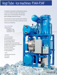
P24A & P34A Service Manual1-1INTRODUCTION1. Introduction<strong>Vogt</strong> <strong>Tube</strong> <strong>Ice</strong>, L.L.C.A Brief History Of Our Company. <strong>Vogt</strong> <strong>Tube</strong> <strong>Ice</strong>, L.L.C. (formerly Henry <strong>Vogt</strong> Machine Co.)was founded as a small machine shop in Louisville, Kentucky in 1880. Today, it is one of theworld’s leading producers of ice-making equipment.In 1938, <strong>Vogt</strong> built the first <strong>Tube</strong>-<strong>Ice</strong> ® machine and revolutionized the ice-making industry. Ourfirst “sized-ice” machine quickly replaced the old can-ice plants, which required hard labor and largeamounts of floor space for freezing, cutting, and crushing ice by hand.<strong>Vogt</strong> Energy-Saving <strong>Tube</strong>-<strong>Ice</strong> Machines Are Cost Effective. Today, <strong>Vogt</strong> <strong>Tube</strong>-<strong>Ice</strong> ® machinesenjoy a well-earned reputation as the most energy efficient, dependable ice-making equipment in theworld.Using as little as one-half to one-third the energy required by competitors’ ice makers, <strong>Tube</strong>-<strong>Ice</strong> ®machines produce the same amount of ice--in restaurants, sports arenas, packing plants, andwholesale operations around the globe--at great savings.In addition, <strong>Tube</strong>-<strong>Ice</strong> ® machines are renowned for their long life, giving many customers more than35 years of dependable service. Ask someone who owns one.Preview. All the skill in engineering and fabrication that we’ve learned in over a century ofexperience is reflected in every <strong>Tube</strong>-<strong>Ice</strong> ® machine. Since <strong>Vogt</strong> introduced <strong>Tube</strong>-<strong>Ice</strong> ® machines in1938, the process of making <strong>Tube</strong>-<strong>Ice</strong> ® ice has been widely recognized as the most economicalmeans of production. The machine’s economic and reliable operation has been proven over andover again, in a network of varied types of installations throughout the world.Furnished with your machine is the Certificate Of Test--the report of operating data that is a recordof the unit’s satisfactory operation at our factory test floor. It is evidence of our desire to deliver toyou “the finest ice-making unit ever made.”This manual is designed to assist you in the installation, start-up, and maintenance of your unit.Your <strong>Tube</strong>-<strong>Ice</strong> ® machine will give you a lifetime of service provided you install, maintain, andservice it properly.Please read your manual carefully before attempting installation, operation, or servicing of thisprofessionally designed piece of equipment. Also, make sure the Warranty Registration/Start-upReport is completed and returned.If you have additional questions, please call your distributor. Also, feel free to phone the factorydirect at (502) 635-3000.8/7/07
1-2INTRODUCTIONP24A & P34A Service ManualImportant Safety Notice. This information is intended for use by individuals possessing adequatebackgrounds in electrical, refrigeration and mechanical experience. Any attempt to repair majorequipment may result in personal injury and/or property damage. The manufacturer or seller cannotbe responsible for the interpretation of this information, nor can it assume any liability in connectionwith its use. It is important that personnel understand the properties of this refrigerant and that theybe thoroughly trained in safe practices for its use and handling. Refer to the enclosed “AnhydrousAmmonia Safety” in Appendix A.Safety Symbols & What They Mean. Prior to installation or operation of the <strong>Tube</strong>-<strong>Ice</strong> ® machine,please read this manual. Are you familiar with the installation, start-up, and operation of a <strong>Tube</strong>-<strong>Ice</strong> ® machine? Before you operate, adjust or service this machine, you should read this manual,understand the operation of this machine, and be aware of possible dangers.These safety symbols will alert youwhen special care is needed.Please heed them.! DANGER !Indicates an immediate hazard and that special precautionsare necessary to avoid severe personal injury or death.! DANGER !! WARNING !Indicates a strong possibility of a hazard and that anunsafe practice could result in severe personal injury.! WARNING !! CAUTION !Means hazards or unsafe practices could resultin personal injury or product or property damage.! CAUTION !8/7/07
P24A & P34A Service Manual1-3INTRODUCTIONSpecial Precautions To Be Observed When Charging Refrigeration Systems. Only technicallyqualifiedpersons, experienced and knowledgeable in the handling of anhydrous ammonia refrigerantand operation of refrigeration systems, should perform the operations described in this manual. Alllocal, federal, and EPA regulations must be strictly adhered to when handling ammonia (R-717)refrigerant. See “Material Safety Data Sheet”, MSDS Code No. 5B81-83.If a refrigeration system is being charged from refrigerant cylinders, disconnect each cylinder whenempty or when the system is fully charged. A gage should be installed in the charging line toindicate refrigerant cylinder pressure. The cylinder may be considered empty of liquid R-717refrigerant when the gauge pressure is 25 pounds or less, and there is no frost on the cylinder. Closethe refrigerant charging valve and cylinder valve before disconnecting the cylinder. Loosen theunion in the refrigerant charging line--carefully to avoid unnecessary, excessive or illegal release ofrefrigerant into the atmosphere.! CAUTION !Immediately close system charging valve at commencement of defrost or thawing cycle ifrefrigerant cylinder is connected. Never leave a refrigerant cylinder connected to systemexcept during charging operation. Failure to observe either of these precautions can result intransferring refrigerant from the system to the refrigerant cylinder, over-filling it, andpossibly causing the cylinder to rupture because of pressure from expansion of the liquidrefrigerant brought on by an increase in temperature.! CAUTION !Always store cylinders containing refrigerant in a cool place. They should never be exposed totemperatures higher than 120°F and should be stored in a manner to prevent abnormal mechanicalshocks.Also, transferring refrigerant from a refrigeration system into a cylinder can be very dangerous andis not recommended.! CAUTION !It is not recommended that refrigerant be transferred from a refrigeration system directly intoa cylinder. If such a transfer is made, the refrigerant cylinder must be an approved, CLEANcylinder--free of any contaminants or foreign materials--and must be weighed continuously toassure contents do not exceed net weight specified by cylinder manufacturer or any applicablecode requirements.! CAUTION !8/7/07
1-4INTRODUCTIONP24A & P34A Service ManualFIGURE 1-1P24A Front Side (Control Panel)8/7/07
P24A & P34A Service Manual1-5INTRODUCTIONFIGURE 1-2P24A Right Side8/7/07
1-6INTRODUCTIONP24A & P34A Service Manual8/7/07FIGURE 1-3P24A Back Side
P24A & P34A Service Manual1-7INTRODUCTIONFIGURE 1-4P24A Left Side8/7/07
1-8INTRODUCTIONP24A & P34A Service ManualFIGURE 1-5P34A Front Side8/7/07
P24A & P34A Service Manual1-9INTRODUCTIONFIGURE 1-6P34A Right Side8/7/07
1-10INTRODUCTIONP24A & P34A Service ManualFIGURE 1-7P34A Back Side8/7/07
P24A & P34A Service Manual1-11INTRODUCTIONFIGURE 1-8P34A Left Side (Control Panel)8/7/07
1-12INTRODUCTIONP24A & P34A Service ManualFIGURE 1-9P24A Compressor Diagram8/7/07
P24A & P34A Service Manual2-1RECEIPT OF YOUR <strong>TUBE</strong>-ICE <strong>MACHINE</strong>2. Receipt Of Your <strong>Tube</strong>-<strong>Ice</strong> Machine! CAUTION !Only service personnel experienced in ammonia refrigeration andqualified to work on high amperage electrical equipment shouldbe allowed to install or service this <strong>Tube</strong>-<strong>Ice</strong> ® machine.Eye protection should be worn by all personnelworking on or around the <strong>Tube</strong>-<strong>Ice</strong> ® machine.It is very important that you are familiar with and adhere toall local, state, and federal, etc. ordinances and laws regardingthe handling, storing, and use of anhydrous ammonia.An approved ammonia mask should be readily availablefor use in an emergency and all personnel should be awareof its location and proper use.! CAUTION !Inspection. As soon as you receive your machine, inspect it for any damage. If damage issuspected, note it on the shipper’s papers (i.e., the trucker’s Bill of Lading). Immediately make aseparate written request for inspection by the freight line’s agent. Any repair work or alteration tothe machine without the permission of <strong>Vogt</strong> <strong>Tube</strong> <strong>Ice</strong>, L.L.C. can void the machine’s warranty. Youshould also notify your <strong>Vogt</strong> distributor or the factory.Description Of Machine. A <strong>Vogt</strong> package <strong>Tube</strong>-<strong>Ice</strong> ® machine is a complete ice producing plantrequiring only make-up water supply, condenser water supply, electrical connection, and the properrefrigerant charge.The machine has been fully factory tested prior to shipment and should require minimumadjustment.After factory testing of the machine, the liquid ammonia is removed and only ammonia gas pressureis allowed to remain. This prevents air or moisture from entering the system during transit. Thereshould be a positive pressure (20-25 psig) indicated on the control panel gages when the machine isreceived.The compressor oil is drained and the compressor suction strainer and cloth filter are cleaned andreinstalled. The crankcase is inspected and cleaned by removing the side handhold cover, swabbingout the remaining oil and wiping the interior sides and bottom with a clean dry cloth. Do not usewoolen fabrics or material which may leave loose fibers. New oil is added and the compressor isevacuated then pressurized with ammonia vapor to 20-25 psig.Refer to your compressor manual for additional operation, service, maintenance instructions, andinformation.Safety Tags and Labels. Be sure to read and adhere to all special tags and labels attached to valvesor applied to various areas of the machine. They provide important information necessary for safeand efficient operation of your equipment.8/7/07
2-2RECEIPT OF YOUR <strong>TUBE</strong>-ICE <strong>MACHINE</strong>P24A & P34A Service ManualThe machine is available in three different tube sizes for producing ice 7/8” OD x 1” long, 1 1/8”OD x 1” long, or 1 3/8” OD x 1” long. The ice is cut to length by a rotating breaker type cutter. <strong>Ice</strong>can be produced up to 1 1/2” long by modifying the spacers under the adapter plates (see Chapter10, “<strong>Ice</strong> Length” for modifying instructions). Crushed ice is also available by modifying the cutterand making minor adjustments to the machine (see Chapter 10, “Crushed <strong>Ice</strong>”).Nominal Capacity"02K" - 2000 lbs/day"03K" - 3000 lbs/day"04K" - 4000lbs/day"03T" - 3 tons/day"05T" - 5 tons/day"10T" - 10 tons/day"25T" - 25 tons/day"50T" - 50 tons/day"80T" - 80 tons/day("K" = 1000's lbs/day, "T" = tons/day)(Consult Specifications for Actual Capacity)Model VariationA number assigned to indicate majorvariations within any one family series.02KA - P F B 4 - 26 AC-RCBasic Configuration"P" - Package"L" - Low-side"H" - High-side<strong>Tube</strong> Size (in 1/4's of an inch)"4" - 1""5" - 1 1/4""6" - 1 1/2""8" - 2"Refrigerant"F" - R-22"A" - Ammonia"H" -R-404aElectrical Codes"26" - 208/230-3-60"46" - 460-3-60"25" - 200-3-50"45" - 400-3-50"21" - 230-1-60Type of <strong>Ice</strong>"B" - Cylinder"K" - Crushed"D" - Dual <strong>Ice</strong> (Cru & Cyl)"L" - 1 1/2" Long CylinderCondenser Type"AC" - Air Cooled"WC" - Water Cooled"HP" - High Pressure Water Cooled"SW" - Sea Water"NC" - No CondenserProduct Variation Codes (A number or letter designator assigned to specific variations within a family.)"000 or Blank" – Standard Product"001" – Pillsbury Job"002" – Liquid Overfeed, Less Control Panels“003” – Liquid Overfeed, Panel shipped separate, No Wiring"RCP" – Remote Control Panel"PWS" – Part-Wind Starter"LOF" – Liquid Overfeed"120" – 120 Volt Controls"FPS" – Freezer Pressure Switch (Instead of timer)"HKA" – Insulated Casings & Part-Wind Start (Hong Kong Airport)"LCP" – Less Control Panel"45T" – Transformer added for 400-3-50, 0_K Models“SSC” – Stainless Steel Casing“VTC” – Von’s Type Cutter“ISC” – Insulated Stainless Steel Casings“SCT” – Stainless Steel Casings and Bin ThermostatFIGURE 2-1Model Designation for P-Series <strong>Ice</strong> Machines8/7/07
P24A & P34A Service Manual2-3RECEIPT OF YOUR <strong>TUBE</strong>-ICE <strong>MACHINE</strong>Rated Capacity. The <strong>Tube</strong>-<strong>Ice</strong> ® machine is rated to produce a given amount of ice when operatingunder the proper conditions as specified in this manual. You should be prepared to handle the iceproduced as it is discharged from the machine and move it to your storage or bagging area promptly.The following specifications are given to help you do just that.Model P24A-1.5” Model P24A-1.25” Model P24A-1”MakeupMakeupWater Capacity Tons/day Water Capacity Tons/dayGPM (2000 lbs/24 hrs.) GPM (2000 lbs/24 hours)MakeupWaterGPMMakeup WaterTemp.Capacity Tons/day(2000 lbs/24 hours)85°F/29°C 19.5 4.06 21.0 4.37 20.0 4.1880°F/24°C 20.0 4.16 21.5 4.48 20.5 4.2775°F/23°C 20.5 4.27 22.0 4.60 21.0 4.3770°F/21°C 21.0 4.38 22.6 4.71 21.5 4.4865°F/18°C 21.6 4.49 23.2 4.84 22.0 4.5960°F/15°C 22.2 4.62 23.9 4.97 22.6 4.7155°F/13°C 22.8 4.75 24.5 5.11 23.2 4.83<strong>Ice</strong> lb/harvest 750 lbs/340 Kg 600 lbs/272 Kg 450 lbs/204 KgShipping weight 12,200 lbs/5533 Kg 12200 lbs/5533 Kg 11,800 lbs/5352 KgOperating weight 14,000 lbs/ 6350 Kg 14000 lbs/6350 Kg 13,450 lbs/6100 KgModel P34A-1.5” Model P34A-1.25” Model P34A-1”MakeupMakeupWater Capacity Tons/day Water Capacity Tons/dayGPM (2000 lbs/24 hrs.) GPM (2000 lbs/24 hours)MakeupWaterGPMMakeup WaterTemp.Capacity Tons/day(2000 lbs/24 hours)85°F/29°C 36.0 7.50 39.5 8.24 35.9 7.4880°F/24°C 36.9 7.69 40.5 8.45 36.7 7.6675°F/23°C 37.8 7.89 41.6 8.67 37.6 7.8470°F/21°C 38.8 8.10 42.7 8.90 38.6 8.0465°F/18°C 39.9 8.32 43.8 9.14 39.6 8.2560°F/15°C 41.0 8.55 45.1 9.39 40.6 8.4755°F/13°C 42.2 8.79 46.4 9.66 41.7 8.70<strong>Ice</strong> lb/harvest 1350 lbs/612 Kg 1300 lbs/589 Kg 850 lbs/385 KgShipping weight 21500 lbs/9750 Kg 21500 lbs/9750 Kg 20900 lbs/9480 KgOperating weight 23000 lbs/10500 Kg 23000 lbs/10500 Kg 22400 lbs/10200 KgNotes:1. Makeup water is average flow and includes 25% blowdown. Peak flow rate is 15 GPM. at 40 PSI minimum. When water quality is good,machine can be operated with 5% to 10% blowdown.2. Ratings are at 90°F ambient for ice machine.3. Capacity ratings are based on 85°F water entering condenser. For entering water temperatures above 85°F, deduct 4% in capacity for each 5°F.4. Capacity shown is the average for model. Individual machines may vary up to 5% above or below depending on field conditions.TABLE 2-1P24A and P34A SpecificationsStorage (prior to installation or start-up). The machine must not be stored or installed in an areathat is subject to reach temperatures at or above 110°F (43.3°C).8/7/07
2-4RECEIPT OF YOUR <strong>TUBE</strong>-ICE <strong>MACHINE</strong>P24A & P34A Service Manual8/7/07
P24A & P34A Service ManualINSTALLING YOUR <strong>TUBE</strong>-ICE <strong>MACHINE</strong>3-13. Installing Your <strong>Tube</strong>-<strong>Ice</strong> MachineYour machine will be shipped to you as one package. You will need to arrange for the handling ofthe package as soon as it arrives, see the machine specifications Table 2-1 for shipping and operatingweight. Before you remove the unit from the truck, be certain that any sign of damage, howeverslight, is noted on the carrier’s papers.Note: See “Lifting Procedure” drawing furnished with this manual, Fig 3-5 and 3-6.Machine Room. The machine must be located inside a suitable building and must not be subjectedto ambient temperatures below 50°F (10°C) or above 110°F (43.3°C). Heat radiation from othersources (sunlight, furnaces, condenser, etc.) and unusual air current may affect the operation of themachine and should be avoided. The electrical components of the <strong>Tube</strong>-<strong>Ice</strong> ® machine are ratedNEMA 1. Therefore, the machine should not be located in a hazardous area or sprayed withwater. The machine should be installed in an area where water will not stand, but will readily drainaway from the machine.Space Requirements. Refer to the space diagrams, Figures 3-1 and 3-3, for recommendedminimum clearance around the machine for ease of servicing and observation. Pay particularattention to the additional space required. If it ever becomes necessary to mechanically clean thecondenser tubes, extra space will be required on one end (preferably on the opposite end from thewater inlet and outlet) for the cleaning tools.Foundation. Refer to the space diagrams, Figures 3-2 and 3-4, for recommended minimumfoundation requirements. The figures show anchor bolt details and machine anchor hole details.Contact your local distributor for seismic anchoring requirements in your area.! WARNING !Lifting or moving heavy equipment should only be attempted bycompetent rigging and hoisting contractors. Never allow personnelnear or under heavy equipment when it is being moved or lifted.Failure to comply could result in personal injury or loss of life.! WARNING !Lifting Procedures. Your <strong>Tube</strong>-<strong>Ice</strong> ® machine is provided with lifting lugs for the purpose ofunloading and moving the machine to its operation location. Refer to the enclosed drawings forinstructions and illustrations of their use.P24A - Figure 3-5. Machine weight 13,000 lbs.P34A - Figure 3-6. Machine weight 22,000 lbs.These figures are intended as a guide to unloading and lifting the P24A and P34A <strong>Tube</strong>-<strong>Ice</strong> ®machine. <strong>Vogt</strong> <strong>Tube</strong> <strong>Ice</strong>, L.L.C. is not responsible for product damage or personnel injury orloss of life during the loading or lifting procedure.8/7/07
3-2INSTALLING YOUR <strong>TUBE</strong>-ICE <strong>MACHINE</strong>P24A & P34A Service ManualFIGURE 3-1AP24A Space Diagram (Front View)8/7/07
P24A & P34A Service ManualINSTALLING YOUR <strong>TUBE</strong>-ICE <strong>MACHINE</strong>3-3FIGURE 3-1BP24A Space Diagram (Side View)8/7/07
3-4INSTALLING YOUR <strong>TUBE</strong>-ICE <strong>MACHINE</strong>P24A & P34A Service Manual8/7/07FIGURE 3-2P24A Foundation Layout
P24A & P34A Service ManualINSTALLING YOUR <strong>TUBE</strong>-ICE <strong>MACHINE</strong>3-5FIGURE 3-3AP34A Space Diagram (Front View)8/7/07
3-6INSTALLING YOUR <strong>TUBE</strong>-ICE <strong>MACHINE</strong>P24A & P34A Service ManualFIGURE 3-3BP34A Space Diagram (Side View)8/7/07
P24A & P34A Service ManualINSTALLING YOUR <strong>TUBE</strong>-ICE <strong>MACHINE</strong>3-7FIGURE 3-4P34A Foundation Layout8/7/07
3-8INSTALLING YOUR <strong>TUBE</strong>-ICE <strong>MACHINE</strong>P24A & P34A Service Manual8/7/07FIGURE 3-5Lifting Procedure for P24A
P24A & P34A Service ManualINSTALLING YOUR <strong>TUBE</strong>-ICE <strong>MACHINE</strong>3-9FIGURE 3-6Lifting Procedure for P34A8/7/07
3-10INSTALLING YOUR <strong>TUBE</strong>-ICE <strong>MACHINE</strong>P24A & P34A Service ManualPiping and Drain Connections. See Figure 1-1 to 1-8 for connection locations.! CAUTION !Exterior shut-off valves must be provided in the waterinlet lines. The minimum inlet water pressure forsatisfactory operation of the machine is 40 psig.The maximum allowable pressure is 100 psig.! CAUTION !ModelMake-upWater InFlushingWater InP24A 3/4” FPT 3/4” FPT72 gal/3 min.P34A 1” FPT 3/4” FPT104 gal/3 min.CompressorCoolingWater InCompressorCoolingWater OutCondenserWaterIn and OutWaterTankDrainWaterTankOverflow3/4” FPT 1” FPT 3” FPT 2” FPT 3” FPT3/4” FPT 1” FPT 5” FPT 2” FPT 3” FPTTABLE 3-1Water Supply and Drain Connections(See FIGURE 1-1 through 1-8 for locations)Make-Up Water In. The water required for ice making must be potable water, safe for humanconsumption, and should be of the highest quality available. The best way to determine waterquality is to have a complete water quality analysis by a qualified laboratory.It is advisable to install a particle filter in the make-up and flushing water lines to trap dirt, sand,rust, or other solid particles prior to entering the water tank and contaminating the ice. Be sure tosize the filter large enough to meet the water demands of 15 GPM (peak flow), allowing for arestriction through the filter as it traps these particles. The inlet water pressure should be a minimumof 40 psi. Refer to TABLE 3-1 for line size and TABLE 2-1 for average flow rate at various watertemperatures.Flushing Water In. Flushing water (blowdown) is necessary to melt ice fines and flush dissolvedsolids from the water tank during the thawing (harvest) cycle. This function is important and helpsto maintain good ice quality. If water quality is superior, this blowdown can be reduced byinstalling a smaller orifice in the flushing outlet elbow. Make sure there is enough flushing water toprevent the accumulation of excessive ice fines in the tank.If make-up and flushing water are from the same source, they can be connected by a common line tothe machine.Compressor Cooling Water In and Out. This water supply should be a maximum temperature of85°F (29°C). It is used for cooling the oil and compressor heads. A thermometer and waterregulating valve are installed at the cooling water outlet. The regulating valve should be adjusted tomaintain a water outlet temperature of 100°F (37.8°C) when the compressor is running. A solenoidvalve is installed at the cooling water supply inlet to prevent water flow through the oil cooler andheads when the compressor is not operating. This is to avoid condensation of refrigerant in thecompressor during shut-down periods. The cooling water outlet should be extended to an opensump or drain in order to observe water flow and temperature and to make sure there is no water8/7/07
P24A & P34A Service ManualINSTALLING YOUR <strong>TUBE</strong>-ICE <strong>MACHINE</strong>3-11flow through the heads during shutdown. Do not connect this drain line into a common header withany drain line from the water tank. Note: The water regulating valve contains a 1/8” orifice throughinter gate to permit some flow though the compressor if the solenoid is open.Water Tank Drain. This valve and connection is for the purpose of flushing and draining the watertank of impurities, foreign material and cleaning chemicals used during servicing. It should be pipedto an open drain or sump for visible discharge. It can be tied in with the overflow line but no others.Water Tank Overflow. A 3” FPT connection on the side of the water tank is provided to carryaway overflow water during the thawing (harvest cycle). This water contains ice fines accumulatedduring harvesting and dissolved solids accumulated during the freezing cycle. Do not reduce thesize of this line. Three inches is needed to provide sufficient area for ice fines to be flushed out,especially if the incoming flushing water is 55°F (13°C) or below. This overflow line should not tiein with any other drain line except the water tank drain.Condenser Water In and Out. One end of the condenser has two water connections. The lowerconnection is the inlet and the upper connection is the outlet. See TABLE 3-2 for waterrequirements and machine total heat rejection. The condenser water outlet must be extended to anopen drain or sump for visible discharge.! CAUTION !The condenser water outlet must not be connected onto a pressure tight commonheader with the water tank due to the possibility that contaminated condenserwater may back up into the water tank. The condenser wateroutlet must be piped separate from the drain or sump.! CAUTION !Cooling Tower. When selecting a cooling tower, careful attention must be given to operating wetbulb conditions. It is advisable to check with your local cooling tower distributor for theirrecommendations based on actual operating conditions in your area. An average wet bulb of 78°F istypical in the U.S., but many localities have designed wet bulbs as low as 72°F or as high as 82°F.The cooling tower water pump must be capable of delivering the required volume of water throughthe condenser. Due to cooling tower location and pressure drop through water lines and regulatingvalves, the water pump must be sized for each installation. Refer to TABLE 3-2 for condenser waterrequirements. The water piping for the cooling tower and the installation of the pump must be inaccordance with the manufacturer’s instructions. Caution must be used to prevent the condenserwater pump from losing it’s prime during off cycles.Proper water treatment for the prevention of mineral and foreign matter accumulation in thecondenser or cooling tower is recommended. A water analysis should be obtained to determine theproper chemicals to use. The use of a 40 mesh strainer in the condenser water supply line is alsorecommended.8/7/07
3-12INSTALLING YOUR <strong>TUBE</strong>-ICE <strong>MACHINE</strong>P24A & P34A Service ManualP24A Condenser WaterP34A Condenser WaterEnteringWaterFlowGPMCond.PSIDEnteringWaterFlowGPMCond.PSID85°F 196 14 85°F 371 1280°F 131 6 80°F 241 575°F 98 3 75°F 185 370°F 79 2 70°F 148 265°F 66 2 65°F 124 160°F 56 1 60°F 106 155°F 49 1 55°F 93 150°F 44 1 50°F 82 1Total Heat RejectionTHR = 981,300 BTUHTotal Heat RejectionTHR = 1,852,500 BTUHCondenser water flow is based on pulldown of 30°F SST and 105°F SDT.Condenser water pressure drop does not include water regulating valve. Consultfactory for sizing if desired.TABLE 3-2Condenser Water RequirementsThe following table show the model of Marley cooling tower required for operating at various wetbulbs to cool 91°F (33°C) entering water to 85°F (29.4°C) exiting water.Model GPMCond. PDPSIG 75°F 76°F 77°F 78°F 79°F 80°FP24A 187 15 4832 4841 4841 4841 4842 4851P34A 371 12 4861 4861 4861 4862 4871 4871TABLE 3-3Marley Cooling Tower RecommendationsTower nozzles will be selected based on GPM required for condenser.The condenser water pump should be sized on GPM required for condenser at 80 ft. total dischargehead for a typical installation. However, due to cooling tower location and pressure drop throughwater lines, the water pump should be sized for each installation.The ice machine is supplied with a fan control switch for cycling the cooling tower fan on and off,thereby maintaining the proper operating head pressure. If the condenser inlet water temperature isexpected to be below 75°F/24°C, a water regulating valve should be installed in the condenser waterinlet line and adjusted to maintain a head pressure of not less than 175 psig.See FIGURES 3-5 through 3-8 for possible cold climate installations with indoor sump.8/7/07
P24A & P34A Service ManualINSTALLING YOUR <strong>TUBE</strong>-ICE <strong>MACHINE</strong>3-13Safety Valves. Four safety pressure relief valves are an integral part of the packaged <strong>Tube</strong>-<strong>Ice</strong> ®machine. Two are located in the low side of the system on the freezer, and two are in the high sideof the system on the receiver. Vent each of the pressure relief valves to the atmosphere in such amanner as to comply with local and national codes. Refer to the International Institute of AmmoniaRefrigeration (IIAR) standard for specific requirements and instructions.8/7/07
3-14INSTALLING YOUR <strong>TUBE</strong>-ICE <strong>MACHINE</strong>P24A & P34A Service Manual8/7/07FIGURE 3-7Cooling Tower Piping Diagram
P24A & P34A Service ManualINSTALLING YOUR <strong>TUBE</strong>-ICE <strong>MACHINE</strong>3-15COOLING TOWERWATERCOOLEDCONDENSERCHECK VALVEINDOOR SUMPFIGURE 3-81 PUMP/2-WAY VALVE* Poor Freeze ProtectionBecause low flow rate = high freeze chanceCOOLING TOWERWATERCOOLEDCONDENSEROnly enough water tomaintain head pressureSame flow rateto cooling towerCHECK VALVEINDOOR SUMPFIGURE 3-91 PUMP/3-WAY VALVE* Better Freeze Protection8/7/07
3-16INSTALLING YOUR <strong>TUBE</strong>-ICE <strong>MACHINE</strong>P24A & P34A Service ManualCOOLING TOWERWATERCOOLEDCONDENSERCHECK VALVEINDOOR SUMPOutdoor pump is off untilindoor sump needs coolingFIGURE 3-102 PUMP/2-WAY VALVE* Best Freeze ProtectionWiring and Electrical Connections.! WARNING !Only service personnel experienced in refrigeration and qualifiedto work with high voltage electrical equipment should be allowedto install or work with the <strong>Tube</strong>-<strong>Ice</strong> ® machine.! WARNING !A fused disconnect must be provided near the <strong>Tube</strong>-<strong>Ice</strong> ® machine. The control panel andcompressor motor starter are attached to the structurals on the front of the <strong>Tube</strong>-<strong>Ice</strong> ® machine (seeFIGURE 3-11). Incoming 3 phase power will be connected at the compressor motor starter (1M).Terminals L1, L2, L3 for operation of the <strong>Tube</strong>-<strong>Ice</strong> ® machine and its controls. Rotation checking ofthe compressor, cutter motor, and water pump is required (see rotation check). Also, if one leg ofthe 3 phase power is higher or lower (“wild”), then it should be connected to terminal L3. Connectthe ground wire to the “ground” terminal provided.Make sure wires #22 and #27 are connected to the elapse time (ET) indicator in the control panel.8/7/07
P24A & P34A Service ManualINSTALLING YOUR <strong>TUBE</strong>-ICE <strong>MACHINE</strong>3-17FIGURE 3-11Power Supply ConnectionsVoltage Unbalance. Voltage unbalance can cause motors to overheat and fail. Voltage imbalancebetween any two legs should be no greater than 2%.Example: Supply voltage = 230-3-60Voltage Readings: AB = 220 VoltsBC = 225 VoltsAC = 227 VoltsAverage = (220 + 225 + 227)/3 = 224 Volts(AB) 224-220 = 4 Volts (Highest Deviation)(BC) 225-224 = 1 Volts(AC) 227-224 = 3 Volts% Voltage Unbalance = 100 x (4/224) = 1.78% “Acceptable”Important: If the supply voltage phase unbalance is more the 2%, contact your localelectric utility company.Current Unbalance. Voltage unbalance will cause a current unbalance, but a current unbalancedoes not necessarily mean that a voltage unbalance exists. A loose terminal connection or a buildupof dirt or carbon on one set of contacts would cause a higher resistance on that leg than on the other8/7/07
3-18INSTALLING YOUR <strong>TUBE</strong>-ICE <strong>MACHINE</strong>P24A & P34A Service Manualtwo legs. Current follows the path of least resistance, therefore if terminal connection L1 is loose ordirty, L2 and/or L3 will have higher current.Higher current causes more heat to be generated in the motor windings. The maximum acceptablecurrent unbalance is 10%.Example:Current Readings:L1 = 96 AmpsL2 = 91 AmpsL3 = 98 AmpsAverage = (96 + 91 + 98)/3 = 95Amps(L1) 96-95 = 1 Amps(L2) 95-91 = 4 Amps (Highest Deviation)(L3) 98-95 = 3 Amps% Current Unbalance = 100 x (4/95) = 4.2% “Acceptable”Rotation Check. The compressor, cutter, and pump motor rotation are factory synchronized, butmust be checked at installation. For cylinder ice production, the cutter disc as viewed at the icedischarge opening should turn from left to right.Check rotation by the following procedure:1. Turn the power to the machine on and check voltages.2. Make sure the water tank is full of clean water.3. Turn the Hand-Auto switch (ISS) to HAND position. The water pump will start and the freezing(1LT) and the liquid feed (2LT) pilot lights will illuminate. Check pump rotation.4. Push the MANUAL HARVEST button. The water pump will stop, the “Freezing and LiquidFeed” lights will go out, and after 20-30 seconds, the cutter motor will start. The thawing gassolenoid valve will open and the “Thawing” pilot light (3LT) will illuminate.5. Check the cutter disc rotation. It should be turning from left to right (CCW looking from thetop).6. Turn the HAND-AUTO switch to AUTO to stop the cutter.To change rotation, follow this procedure:1. Disconnect power to the machine and lock it out to make sure it can’t be turned back on.2. Check for power at L1, L2, L3 with a volt meter to make sure it is off.3. At the compressor motor starter (1M) or at the power disconnect, reverse wires L1 and L2.4. Make sure these terminals are tight and restore power to the machine.5. Perform rotation check again to confirm that it is correct.! CAUTION !Do not attempt to start the compressor motor until first making sure allconditions listed in the Installation Review Checklist and allnecessary valves have been opened for operation.! CAUTION !8/7/07
P24A & P34A Service ManualINSTALLING YOUR <strong>TUBE</strong>-ICE <strong>MACHINE</strong>3-19Auxiliary Controls or Equipment. When connecting other equipment such as tower fan,condenser pump, conveyor motors, bin level control, etc., refer to the control panel wiring drawingfor the proper connecting terminals and instructions. See Figure 6-3.8/7/07
3-20INSTALLING YOUR <strong>TUBE</strong>-ICE <strong>MACHINE</strong>P24A & P34A Service Manual! IMPORTANT !Be sure to follow the wiring schematic when incorporating overloads ofconveyor, fan, or pump motor starters (i.e., 5 MOL, 6 MOL, 7 MOL). Alsoremove jumpers as instructed. This is necessary to provide properprotection for the <strong>Tube</strong>-<strong>Ice</strong> ® machine and its component parts.! IMPORTANT !Installation Review: A Checklist. Make a visual check to be sure these steps have been takenBEFORE continuing.CHECK: _____ PRIOR TO OPENING VALVES, check all joints for leaks which may havedeveloped during shipment. (NOTE: the machine was shipped with a positive pressure of 20-25PSIG, which should be indicated on the suction and discharge gages.)CHECK: _____ All water supply and drain connections for conformity to requirements stipulated inthis manual and properly connected to inlets and outlets.CHECK: _____ Electrical supply for proper size of fuses and for compliance to local and nationalcodes. See the machine nameplate for minimum circuit ampacity and maximum fuse size.CHECK: _____ All field installed equipment (augers, conveyors, cooling towers, bin level controls,etc.) for proper installation.CHECK: _____ The applicable portion of the warranty registration/start-up report for propercompletion.CHECK: _____ Cutter gear reducer oil level oil should run out of side pipe plug when removed.CHECK: _____ The water distributors at top of freezer to make sure they are all in position (oneseated firmly in each tube with a vent tube in each distributor).! CAUTION !The crankcase heater should be energized for a minimum offour hours and the oil temperature should be 100-110°Fbefore attempting to start the compressor.! CAUTION !8/7/07
P24A & P34A Service ManualHOW YOUR <strong>TUBE</strong>-ICE <strong>MACHINE</strong> WORKS4-14. How Your <strong>Tube</strong>-<strong>Ice</strong> Machine WorksOperating Features. Your packaged <strong>Tube</strong>-<strong>Ice</strong> ® machine is an efficient ice producing plant. Ifinstalled and maintained properly, it will give many years of operation with a minimum amount ofrepairs. Refer to piping schematics, FIGURE 4-1 and 4-2 to identify component parts whilefollowing the information and instructions in this manual.The machine is manually started and stopped by the START and STOP push buttons. The machinewill automatically stop by safeties such as compressor, cutter and pump overloads, as well as otherauxiliary motor overloads. It will also stop automatically by high head pressure, low suctionpressure or low compressor oil pressure. The circulating water pump can be operated independentlyfor chemically cleaning the freezer tubes and water tank by use of the HAND/AUTO selectorswitch. The machine can be manually forced into a harvest cycle with the manual harvest pushbutton.Principle of Operation. The freezer (2) is a shell and tube-type vessel. During the freezing period(cycle), water is constantly recirculated through the vertical tubes of the freezer by a centrifugalpump (6). Make-up water is maintained by a float valve (12) in the water tank (7). The float switch(10) opens and closes the liquid feed “A” solenoid valve (20) and maintains the desired refrigerantlevel in the freezer (2) (evaporator).Refrigerant gas from the top of the freezer (2) passes through the suction accumulator (88) and to thecompressor (3). Here, the cool gas is compressed to a high temperature, high pressure gas whichdischarges through the oil separator (14), then through the heat coil of the condenser and then intothe P24 condenser/receiver (15). P34A condenser (15C)/receiver (15R). In the condenser, heat isremoved and the gas is condensed to a high temperature, high pressure liquid. The high pressureliquid goes out the liquid line through a strainer (43), liquid “A” solenoid valve (20) check valve(101), and hand expansion valve (17). At the hand expansion valve (17), the refrigerant expandsfrom a saturated high pressure liquid state to a low pressure, low temperature liquid. This coldliquid enters the freezer (2) where it absorbs heat from the circulating water in the freezer tubes.Cool gas is again pulled out of the freezer through the suction outlet, thereby completing the circuit.The freezing period is completed by action of the freezer pressure switch (2PS) in the control panel.The water pump (6) stops and the “A” solenoid valve (20) closes. After a delay of 20-30 seconds,the cutter motor starts, the thawing gas “D” solenoid valve (18) opens, and the harvest (thawing)timer (2TR) is activated. Warm gas from the receiver is discharged through the thawing chamber(16), check valve (101), and into the freezer. There it warms the refrigerant and the outer surface ofthe freezer tubes, allowing the ice to release on the inside of the tubes and drop down onto therotating cutter for sizing. After sizing, the ice drops on the tines cutter disc and discharged throughthe ice discharge opening.See “Freeze Period” and “Harvest Period” for more detailed description of machine.Freeze Period. The <strong>Tube</strong>-<strong>Ice</strong> ® is frozen inside the stainless steel tubes of the freezer (2) by thedirect application of refrigerant to the outside shell side of the tubes. <strong>Ice</strong> is produced fromconstantly recirculating water down each tube. As the ice thickness increases, the freezer suctionpressure decreases. At a set pressure, the freezer pressure switch (2PS) energizes the relay (1CR),which stops the water pump, closes the “A” liquid feed solenoid valve (20), turns out the two pilotlights, ammonia feed and freezing.8/7/07
P24A & P34A Service ManualHOW YOUR <strong>TUBE</strong>-ICE <strong>MACHINE</strong> WORKS4-38/7/07FIGURE 4-1Piping Schematic for P24A
4-4HOW YOUR <strong>TUBE</strong>-ICE <strong>MACHINE</strong> WORKSP24A & P34A Service Manual8/7/07FIGURE 4-2Piping Schematic for P34A
P24A & P34A Service ManualSTART-UP & OPERATION5-15. Start-Up & OperationRefrigeration System Review. The refrigeration system uses anhydrous ammonia (R-717)refrigerant. Following the piping schematic (Figure 4-1 or 4-2), you will see that during themachine’s freeze cycle, the compressor discharge gas goes through the oil separator (14) to removeany oil present in the discharge gas and return the oil to the compressor crankcase. From the oilseparator, the discharge gas continues through a heat coil in the lower part of the condenser/receiver(15). 1 It is then discharged into the condenser and condensed into a liquid by the removal of heat bywater passing through the condenser tubes. A reservoir of liquid R-717 (approximate 375 lbs forP24A and 625 lbs. for P34A) is accumulated in the receiver and is required for thawing purposes.Liquid from the receiver flows through the strainer to the “A” solenoid valve (20) which opens andcloses by action of the low side float switch (10). The liquid is then expanded through the handexpansion valve (17) and into the evaporator (2) (freezer). The cold wet R-717 refrigerant floods theevaporator and is in contact with the outside of the ice making tubes which water is being circulatedthrough. The heat contained in the water passes through the wall of the tubes, lowering thetemperature of the water causing it to freeze and form a long tube of ice that adheres to the inside offreezer tubes. Since the purest water freezes first, the circulating water continues to wash thedissolved solids down into the sump area of the water tank. The flushing valve helps to rid the watertank of increased dissolved solids by flushing them out the overflow during the harvest (thawing)period.The wet suction gas leaves the freezer and passes through the suction accumulator (88), where liquiddroplets are removed, allowing dry gas to enter the suction side of the compressor. The suction gasis then compressed and discharged once again, completing the cycle. As ice continues to form in thefreezer tubes, the suction pressure steadily decreases until the freezer pressure switch is satisfied andthe contact closes, initiating the thaw (harvest) cycle.Note: Freezing time will vary, depending on make-up water temperature and thickness of iceproduced.During the harvest period, the “D” thawing gas valve (18) opens and the compressor unloads,allowing the warm high pressure gas from the receiver to enter the freezer. As the tubes warm up toslightly above freezing, the ice inside the tubes releases and falls down onto the rotating cutter forsizing and discharging. Harvesting requires about three minutes, but can vary depending on icethickness, suction pressure, and discharge pressure (thawing gas temperature).! IMPORTANT !It is a good idea and will be profitable for you to observe andbecome familiar with the proper operating characteristics of your<strong>Tube</strong>-<strong>Ice</strong> ® machine. It will help you to recognize and correct minorirregularities as they occur in order to help prevent major problems.“An ounce of prevention is worth a pound of cure.”! IMPORTANT !1 Note: in the P24A the condenser and receiver are combined. In the P34A the condenser and the receiver are separated. The P34A receivercontains the heating coil.8/7/07
5-2START-UP & OPERATIONP24A & P34A Service ManualStart-up Checklist. Be sure to complete and return the “Warranty Registration/Start-up Report”located in the front of the manual.1. See that the water-inlet connections are attached properly. The water inlet shutoff valve (62) forthe water tank should be open. The water level in the water tank should be at a height where themake-up float valve will be closed when the machine is idle and water is not running out of theoverflow (9).2. See that the condenser cooling water is connected properly and the valves are opened forcirculation.3. Fill the cooling tower sump and check the tower manufacturer’s installation and operationinstructions to make sure it is ready to run.4. Check condenser cooling water pump rotation.5. Check rotation of augers or ice handling equipment to make sure they are rotating the properdirection.6. Check all tagged valves and make sure they are in their correct operational position (opened,closed, or automatic).7. See that the electrical disconnect is closed and the proper power is supplied to the machine.8. See that the compressor oil temperature is 100-110°F and there is no liquid ammonia in thecrankcase. The oil level should be 1/2-3/4 of the sight glass.9. Check the elapsed time indicator (ET) and make sure wire #22 and #27 are attached.10. Reconfirm “Rotation Check” for compressor, cutter and water pump (See Section 3).Refrigerant Charge. Prior to charging the machine with anhydrous ammonia (R-717) make surethe system is leak tight and free of non-condensibles or other contaminants.The machine will require a full charge of pure anhydrous ammonia. Make sure it is from a reputablesupplier who can and will furnish quality ammonia of Refrigeration or Federal Technical grade.GradeMinimumAmmonia ContentMaximumWater ContentMaximumOil ContentMaximum NoncondensableFertilizer 99.50% 5000 PPM 5 PPM N/ARefrigeration 99.98% 150 PPM 3 PPM .2 ml/gFederal Technical 99.98% 200 PPM 5 PPM NoneMetallurgical 99.99% 33 PPM 2 PPM 10 ml/gResearch 99.999% 5 PPM 1 PPM 7 PPMTABLE 5-1Ammonia Specification By Grade(Reference IIAR Ammonia Data Book Chapter 1, General Information)NOTE: Do not use Fertilizer grade ammonia.Total ammonia (R717) charge required is approximately;P24A = 800 lbs.P34A = 1600 lbs.Special precautions to be observed when charging refrigeration systems. Only technicallyqualified persons, experienced and knowledgeable in the handling of anhydrous ammonia refrigerantand operation of refrigeration systems should perform the operations described in this manual. Alllocal, federal, and EPA regulations must be strictly adhered to when handling ammonia (R717)refrigerants. See “Material Safety Data Sheet”, MSDS Code5B81-83, located in the Appendix A.8/7/07
P24A & P34A Service ManualSTART-UP & OPERATION5-3Charging From Tank Truck. The machine may be charged by bulk from a tank truck and bepumped directly into the receiver through the drain valve (44).Follow these instructions with caution:1. Using a ammonia approved charging hose, connect one end to the charging valve (44) in thebottom of the receiver.2. Connect the other end of the charging hose to the tank truck. It is best to have a gage in this lineto indicate pressure.3. Open the charging valve (44) and the fill valve from the tank truck.4. Fill the receiver to the indicated mark on the sight glass (30).! CAUTION !Do NOT attempt to bulk charge the machine through the freezercharging valve (28). The freezer will not hold the full chargewithout exposing the compressor to serious damage.! CAUTION !Charging From Cylinders. The machine may also be charged from refrigerant cylinders. Tocharge from cylinders, the compressor will have to operate to transfer the ammonia from the freezerto the receiver. Again, make sure all the necessary valves are opened for operation and thecompressor crankcase heater has been energized for a minimum for four hours.Follow these instructions with caution:1. Using a approved for ammonia charging hose, connect one end to the charging valve (28) in theliquid line near the freezer.2. Lay a full cylinder of anhydrous ammonia horizontally with the cylinder valve outlet pointing upto withdraw liquid and the bottom end raised about 2” higher than the top end.3. Connect the other end of the charging hose to the cylinder valve. It is recommended that a gagebe attached to this line to indicate cylinder pressure.4. Close the liquid line stop valve (29) or (58).5. Open charging valve (28) and carefully purge air from the charging hose.6. Open the cylinder valve slowly, checking for leaks in the line and allow the suction pressure tobuild up to approximately 40 psig and check again for leaks in the system.7. With the power off, open the control panel door and disconnect wire #24 from the freezerpressure switch (2PS), then turn the power back on.8. Check compressor rotation by starting and stopping the compressor momentarily using the green“Start” push button (2PB) and the red “Stop” push button (1PB). Correct compressor rotation isindicated by an arrow on the outer rim of the oil pump assembly (opposite the shaft end of thecompressor.9. Set the Hand/Auto switch (1SS) to the “Hand” position allowing the circulating water pump tocirculate water through the freezer.10. As the pressure continues to rise in the freezer, start the compressor and pump the ammonia intothe receiver. Make sure water is circulating through the condenser and freezer tubes.If a refrigeration system is being charged from refrigerant cylinders, disconnect each cylinder whenempty or when the system is fully charged. A gage should be installed in the charging line toindicate refrigerant cylinder pressure. The cylinder may be considered empty of liquid R-7178/7/07
5-4START-UP & OPERATIONP24A & P34A Service Manualrefrigerant when the gauge pressure is 25 pounds or less and there is no frost on the cylinder. Closethe refrigerant charging valve and cylinder valve before disconnecting the hose from the cylinder.Loosen the union in the refrigerant charging line--carefully to avoid liquid ammonia release into theatmosphere.! CAUTION !Immediately close system charging valve at commencement of defrost orthawing cycle if refrigerant cylinder is connected. Never leave a refrigerantcylinder connected to system except during charging operation. Failureto observe either of these precautions can result in transferringrefrigerant from the system to the refrigerant cylinder, over-filling it,and possibly causing the cylinder to rupture because of pressurefrom expansion of the liquid refrigerant.! CAUTION !Transferring refrigerant from a refrigeration system into a cylinder can be very dangerousand is not recommended.As the machine is being charged, continually observe the following operating characteristics:a) Discharge pressure - 175 psi to 200 psi maximumb) Compressor oil pressure - (Mycom) 18-27 psi above suction, (Vilter 35-50 psi above suction)c) Liquid level in receiver - marked on gage glass guardd) Compressor cooling water - 100°F outlet temperaturee) Compressor oil level - approximately 1/2 glassWhile charging the machine, the low pressure switch will stop operation at approximately 15 psisuction pressure. The switch will automatically reset at 35 psi at which time you can restart themachine. It is best to use warm water in the tank and open the tank drain valve somewhat to allowcold water to exit and warm water to enter continually. The idea is to prevent ice from freezing inthe tubes as much as possible while charging. It may be necessary to initiate a short harvest cycle todispel any ice made. To initiate a harvest cycle, close the charging valve and push the manualharvest push button (3PB) while the compressor is running. As soon as all the ice clears the cutterarea, turn the Hand/Auto switch to “Hand” and then back to “Auto”. This will stop the harvest andstart another freeze to continue the charging procedure. When the liquid level in the receiver is nearthe pumpdown level and the freezer is down to 15 psi suction with little of no frost on the shell, youcan stop the charging procedure and disconnect the cylinder. Make sure the charging valve is closedand the cylinder valve is closed before attempting to disconnect the cylinder. Loosen the union in thecharging line gradually to relieve the ammonia pressure slowly.When charging is complete, stop the machine, disconnect and lock-out the power. Open the controlpanel door and reconnect wire #24 to the freezer pressure switch. Open valves #29 and #58 in theliquid line and you will hear liquid refrigerant flowing through to the liquid solenoid valve #20.Turn main power disconnect to the on position and the machine is read for start-up and iceproduction.8/7/07
P24A & P34A Service ManualSTART-UP & OPERATION5-5FIGURE 5-1.Control PanelStart-Up. Starting the machine can be accomplished as follows:1. Make sure the crankcase oil temperature is approximately 100°F and there is no liquid ammoniain the compressor crankcase.2. Turn the Hand/Auto switch (1SS) to the “Hand” position and allow the water tank to refill.MAKE SURE THE DRAIN VALVE IS CLOSED.3. Push the green “Start” push button to start the compressor and immediately observe the oilpressure, the oil level, the discharge pressure, and listen for any unusual sounds. Thecompressor starts unloaded and will load automatically after several seconds by action of thedelay timer (DT).4. Turn the Hand/Auto switch to the “Auto” position.5. When the discharge pressure increases to about 170 psi, push the “Manual Harvest” button toinitiate the harvest cycle. See “Harvest Period”.6. When the suction pressure raises to 50-55 psig, any ice made should release and discharge.After all of the ice clears the cutter and auger, turn the Hand/Auto switch to “Hand” and back to“Auto”. This will interrupt the harvest cycle and start another freeze cycle. See “Freeze Cycle”.As the machine continues its freezing cycle, the liquid ammonia will feed into the freezer until thelevel float switch (10) is satisfied. The float switch will open and close the liquid line solenoid valve(20) to maintain that level of ammonia in the freezer during the freeze cycle. When the suctionpressure pulls down to the setting of the freezer pressure switch (2PS), the switch will close andinitiate the harvest cycle. See “Harvest Period”.8/7/07
5-6START-UP & OPERATIONP24A & P34A Service ManualBe sure to observe several complete cycles of ice production to confirm the satisfactory operation ofthe machine.! IMPORTANT !Complete the remaining part of the “Warranty/Registration Start-Up Report”and return it to <strong>Vogt</strong> <strong>Tube</strong> <strong>Ice</strong>, L.L.C.! IMPORTANT !Check the refrigerant level at the receiver liquid gage glass to make sure it is near the operating levelmark.Adding Refrigerant. Add refrigerant while the machine is running by the following procedure:1. With a cylinder of anhydrous ammonia laying on its side, cylinder valve outlet pointing up andbottom end raised two inches higher than the valve end, connect an “approved for ammonia”charging hose between the freezer charging valve (28) and the cylinder valve.2. Purge all air from the charging hose and open the cylinder valve gradually to check for possibleleaks around the packing nut or hose fittings. Then open the cylinder valve fully.3. While the “ammonia feed light is not illuminated, open the charging valve (28) and ammoniawill flow from the cylinder to the freezer.4. Close the cylinder valve immediately when the ammonia feed light comes on and reopen it whenthe light goes out. Repeat until properly charged.! CAUTION !Do not leave a refrigerant cylinder attached to the machine unattended.Disconnect it immediately when the machine is charged or the cylinder is empty.! CAUTION !Operating Tips.• Make sure the machine is left running in the “Auto” position. This will assure a completeshutdown if a safety or overload is tripped.• To initiate a harvest cycle, simply push the Manual Harvest push button (3PB).• To interrupt the harvest cycle and revert to a freeze cycle, turn the Hand/Auto switch to “Hand”and back to “Auto”.• Too much ammonia in the condenser/receiver can contribute to high discharge pressure. Do notgo above 13 ½” for the P24A or 25” for the P34A from the center of the lower gage glass cockwhile in normal operation. A higher level can begin to cover the condenser tubes and reducecondenser efficiency.• The circulating water overflow tubing will show that water is being slightly lifted up the tubingnear the end of the freezing cycle. If this action ceases and water begins overflowing from thetop water box, it is an indication that the tubes are freezing solid and the machine should begin aharvest cycle. It is best not to freeze the ice solid with no hole.• To cease ice production manually, allow the machine to complete the harvest period and start thefreeze period. When the “liquid feed” light comes on at the beginning of the freeze period, pushthe “Stop” button to cease ice production.8/7/07
P24A & P34A Service ManualELECTRICAL CONTROLS6-16. Electrical ControlsYour packaged <strong>Tube</strong>-<strong>Ice</strong> ® machine is equipped with a compressor motor starter (1M) as required foryour particular voltage and a transformer (if required) for the control circuit power. The motorstarter and transformer are mounted on the machine front side (see Figures 1-1 or 1-8).The control panel wiring schematic, FIGURE 6-3, illustrates these components as well as provisionsfor auxiliary equipment which may be incorporated by the customer such as:(FU1) Main power disconnect(5M) Conveyor motor starter and overload (5MOL)(6M) Tower fan starter and overload (6MOL)(7M) Condenser pump starter and overload (7MOL)When adding motor starters for auxiliary equipment, be sure to incorporate the overload protectionas indicated between terminals #12-#13 and remove the jumper wire. This will assure that themachine will shutdown when any auxiliary equipment fails.Bin Level Control. Included in the wiring schematic is provision for a bin level control (BLC).The NC contract of your control should be wired between terminals #8-#9 and the jumper wireremoved as indicated. Installation in this manner will allow the machine to finish the harvest periodbefore shutdown. However, the machine will still need to be manually started to resume production.Safety Switches. The machine is also equipped with the following safeties and control switches,which are mounted to the frame near the compressor. Refer to the wiring schematic FIGURE 6-3 fortheir circuitry.• High/Low dual pressure switch (1PS) to stop the machine if the compressor suction pressuregoes too low (15-20 psi) or the compressor discharge pressure goes too high (225-250 psi). See“High/Low Pressure Switch”.• Oil failure pressure switch (0PS) to stop the machine if the compressor oil pressure drops to 15psi net (suction pressure minus oil pressure gage reading). See “Oil Pressure Switch”.• Fan control switch to maintain a desirable head pressure (discharge pressure) of 175 to 200 psiduring operation. See “Fan Control Switch”.8/7/07
6-2ELECTRICAL CONTROLSP24A & P34A Service Manual(1M) Not shownCompressor MotorStarterFIGURE 6-1Control Panel (Door Opened)Provides power to the compressor motor. Continuously energizedduring freezing and thawing with auxiliary hold contact andauxiliary contact to de-energize the compressor crankcase heaterwhen the motor is running.(2M) Pump Motor Starter Provides power to the circulating water pump during the freezerperiod or when the Hand/Auto switch is in the “Hand” position tocirculate water or ice machine cleaner, etc.(3M) Cutter Motor Starter Provides power to the cutter during the harvest period.(1CR)Control Relay WithPneumatic TimerFor making and breaking various circuits during freezing andthawing period with pneumatic timer to delay the actual thawingprocess. Energized during thawing.(2CR) Control Relay For making and breaking circuits during freezing and thawing.Energized during freezing, thawing, and hand. Momentarily deenergizedat the end of the harvest.(2TR) Thawing Timer Controls the time of the harvest (thawing) period.Energized during the harvest period.(DT) Delay Timer Allows the compressor to start unloaded by delaying the energizingof the “UR-SOL” (unloader solenoid) valve. This gives lower inrush amps and helps prevent belt slippage at start-up.(2PS) Freezer Pressure Switch Controls the desired ice thickness (hole size) by sensing the freezersuction pressure and initiating the harvest period.(ET) Elapsed Time Indicator Indicates total hours of machine operation. Is powered when thecompressor is running.(CB4) Circuit Breaker Overload and short circuit protection for crankcase heater and thecontrol circuit.(CB2) Circuit Breaker Secondary protection for the circulating water pump motor.(CB3) Circuit Breaker Secondary short circuit protection for the cutter motor.(TB) Terminal Block Numbered for multiple wire connections and ease oftroubleshooting.TABLE 6-1Description of Control Panel Parts (Inside)8/7/07
P24A & P34A Service ManualELECTRICAL CONTROLS6-3FIGURE 6-2Control Panel (Hinged Door)(1LT) Amber Pilot Light - Freezing Illuminated during the freeze period or whenever thecirculating water pump is running.(2LT) Clear Pilot Light - Liquid Feed Illuminated when the circulating water pump is running andthe float switch (10) is closed. Indicates that the liquid linesolenoid valve (20) is opened.(3LT) Red Pilot Light - Thawing Illuminated when the machine is in a harvest period.(2PB) Green Push Button - Start For starting the compressor motor and ice production. (NO)(1PB) Red Push Button - Stop For stopping the compressor motor and ice production. (NC)(3PB)White Push Button - Manual For manually initiating a harvest cycle. (NO)Harvest(1SS) Selector Switch - Hand/Auto “Hand” position for running the circulating water pumpindependently at start-up or for cleaning the freezer tubes andwater tank.“Auto” position for provision of automatic system shutdownif there is a control circuit power interruption.TABLE 6-2Description of Control Panel Parts (Outer Door)8/7/07
6-4ELECTRICAL CONTROLSP24A & P34A Service Manual8/7/07FIGURE 6-3Electrical Schematic for P24A and P34A all Voltages, 50-60 Hz.
P24A & P34A Service ManualELECTRICAL CONTROLS6-16. Electrical ControlsYour packaged <strong>Tube</strong>-<strong>Ice</strong> ® machine is equipped with a compressor motor starter (1M) as required foryour particular voltage and a transformer (if required) for the control circuit power. The motorstarter and transformer are mounted on the machine front side (see Figures 1-1 or 1-8).The control panel wiring schematic, FIGURE 6-3, illustrates these components as well as provisionsfor auxiliary equipment which may be incorporated by the customer such as:(FU1) Main power disconnect(5M) Conveyor motor starter and overload (5MOL)(6M) Tower fan starter and overload (6MOL)(7M) Condenser pump starter and overload (7MOL)When adding motor starters for auxiliary equipment, be sure to incorporate the overload protectionas indicated between terminals #12-#13 and remove the jumper wire. This will assure that themachine will shutdown when any auxiliary equipment fails.Bin Level Control. Included in the wiring schematic is provision for a bin level control (BLC).The NC contract of your control should be wired between terminals #8-#9 and the jumper wireremoved as indicated. Installation in this manner will allow the machine to finish the harvest periodbefore shutdown. However, the machine will still need to be manually started to resume production.Safety Switches. The machine is also equipped with the following safeties and control switches,which are mounted to the frame near the compressor. Refer to the wiring schematic FIGURE 6-3 fortheir circuitry.• High/Low dual pressure switch (1PS) to stop the machine if the compressor suction pressuregoes too low (15-20 psi) or the compressor discharge pressure goes too high (225-250 psi). See“High/Low Pressure Switch”.• Oil failure pressure switch (0PS) to stop the machine if the compressor oil pressure drops to 15psi net (suction pressure minus oil pressure gage reading). See “Oil Pressure Switch”.• Fan control switch to maintain a desirable head pressure (discharge pressure) of 175 to 200 psiduring operation. See “Fan Control Switch”.8/19/04
6-2ELECTRICAL CONTROLSP24A & P34A Service Manual(1M) Not shownCompressor MotorStarterFIGURE 6-1Control Panel (Door Opened)Provides power to the compressor motor. Continuously energizedduring freezing and thawing with auxiliary hold contact andauxiliary contact to de-energize the compressor crankcase heaterwhen the motor is running.(2M) Pump Motor Starter Provides power to the circulating water pump during the freezerperiod or when the Hand/Auto switch is in the “Hand” position tocirculate water or ice machine cleaner, etc.(3M) Cutter Motor Starter Provides power to the cutter during the harvest period.(1CR)Control Relay WithPneumatic TimerFor making and breaking various circuits during freezing andthawing period with pneumatic timer to delay the actual thawingprocess. Energized during thawing.(2CR) Control Relay For making and breaking circuits during freezing and thawing.Energized during freezing, thawing, and hand. Momentarily deenergizedat the end of the harvest.(2TR) Thawing Timer Controls the time of the harvest (thawing) period.Energized during the harvest period.(DT) Delay Timer Allows the compressor to start unloaded by delaying the energizingof the “UR-SOL” (unloader solenoid) valve. This gives lower inrush amps and helps prevent belt slippage at start-up.(2PS) Freezer Pressure Switch Controls the desired ice thickness (hole size) by sensing the freezersuction pressure and initiating the harvest period.(ET) Elapsed Time Indicator Indicates total hours of machine operation. Is powered when thecompressor is running.(CB4) Circuit Breaker Overload and short circuit protection for crankcase heater and thecontrol circuit.(CB2) Circuit Breaker Secondary protection for the circulating water pump motor.(CB3) Circuit Breaker Secondary short circuit protection for the cutter motor.(TB) Terminal Block Numbered for multiple wire connections and ease oftroubleshooting.TABLE 6-1Description of Control Panel Parts (Inside)8/19/04
P24A & P34A Service ManualELECTRICAL CONTROLS6-3FIGURE 6-2Control Panel (Hinged Door)(1LT) Amber Pilot Light - Freezing Illuminated during the freeze period or whenever thecirculating water pump is running.(2LT) Clear Pilot Light - Liquid Feed Illuminated when the circulating water pump is running andthe float switch (10) is closed. Indicates that the liquid linesolenoid valve (20) is opened.(3LT) Red Pilot Light - Thawing Illuminated when the machine is in a harvest period.(2PB) Green Push Button - Start For starting the compressor motor and ice production. (NO)(1PB) Red Push Button - Stop For stopping the compressor motor and ice production. (NC)(3PB)White Push Button - Manual For manually initiating a harvest cycle. (NO)Harvest(1SS) Selector Switch - Hand/Auto “Hand” position for running the circulating water pumpindependently at start-up or for cleaning the freezer tubes andwater tank.“Auto” position for provision of automatic system shutdownif there is a control circuit power interruption.TABLE 6-2Description of Control Panel Parts (Outer Door)8/19/04
6-4ELECTRICAL CONTROLSP24A & P34A Service Manual8/19/04FIGURE 6-3Electrical Schematic for P24A and P34A all Voltages, 50-60 Hz.
P24A & P34A Service Manual 7-1MAINTENANCE7. MaintenancePreventative Maintenance. A careful inspection of the <strong>Tube</strong>-<strong>Ice</strong> ® machine for leaks and correctoperational functions at the time of installation and start-up will begin its long satisfactory life ofservice. In order to insure this degree of dependability, a systematic maintenance program isnecessary. Therefore, the following schedule is suggested as a minimum.A. Daily1) Check operating pressures (suction, discharge, oil).2) Check ice quality.3) Check “ice out” time (maintain 30 seconds of continued harvest after last ice is out).4) Check compressor oil level.5) Check refrigerant operation level.6) Check frost pattern on freezer shell and oil trap.7) Check make-up water float valve adjustment.8) Rotate the Mycom-Cuno oil filter - tee handle two complete turns.B. Weekly (in addition to daily checks)1) Check all belts for proper tension. Do not use belt dressings.2) Check for leaks after 400 hours or four weeks of operationC. Monthly (in addition to weekly checks)1) Check calibration and operation of all controls (high and low pressure switches, oil pressureswitch, etc).2) Check cooling tower spray nozzles and pump suction screen for scaling and algae (consultwater treatment suppliers for corrective measures).3) Check water distributors in freezer for scale accumulation.4) Check water tank for solids to be removed.5) Check all motor drive units (compressor, cutter and pump motors, cooling tower fan, andpump, etc) for abnormal noise and/or vibrations.6) Check oil level in gear reducer.7) Check one complete freeze/thaw cycle, record data and compare with production check ofRegistration/Start-up Report.D. Yearly (in addition to weekly and monthly)1) Check entire system for leaks.2) Drain water from condenser and cooling tower and check condenser tubes. Check closelyfor damage by corrosion or scale.3) Remove all rust from all equipment, clean, and paint.4) Check all motors for shaft wear and end play.5) Check operation and general condition of all electrical controls, relays, motor starters, andsolenoid valves.6) Check freezing time, ice release time, and ice out time.7) Change oil in gear reducer box once a year.8) Lubricate compressor motor bearings.9) Drain compressor oil, open compressor, inspect and clean inside crankcase. Change oilfilter and add new oil. Inspect compressor suction strainer.8/7/2007
7-2 P24A & P34A Service ManualMAINTENANCEPREVENTATIVE MAINTENANCE FORMThis form can be removed and duplicated for record keeping.Date: _____________ Model #: ________________________ Serial #: _____________The following service performed and checked:Hour meter reading _______________ , Ambient temperature (inside)_______ °FMake-Up water float valve adjusted properlyWater distributors clean and in placeAll drains freely drainingCleaned and flushed water tankCompressor oil changedCleaned and inspected inside compressor crankcaseChanged compressor oil filterChecked/adjusted compressor belt tensionLubricate compressor motor bearingsCheck/change cutter gear reducer oilCheck/adjust cutter drive gear meshingLeak check entire systemCheck liquid refrigerant level in receiverDrained oil from oil trapCompressor crankcase heater workingCompressor net oil pressure (gage reading less suction)Motor amps: Compressor ________ Cutter ________ Pump ________Suction psig (end of freeze) __________ Discharge psig (end of freeze)_____________Suction psig (end of thaw) __________ Discharge psig (end of thaw) _____________Compressor water out ____°F Tower fan cycles ___ On ___ OffProduction CheckTestCycle#1#2#3#4Make-upWaterTempFreezingTimeMin/SecHarvestTimeMin/SecFirst<strong>Ice</strong> OutMin/SecAll<strong>Ice</strong> OutMin/SecAvg.HoleSize<strong>Ice</strong> lb.Per Harvest(est)<strong>Ice</strong> lb.Per Day(est)Comments: _________________________________________________________________________________________________________________________________________________________________________________________________________________________________________Name: __________________________________8/7/2007
P24A & P34A Service Manual 7-3MAINTENANCE<strong>Ice</strong> Making Section. The ice making section of the <strong>Tube</strong>-<strong>Ice</strong> ® machine should be cleaned at leasttwice a year (more often if water conditions cause mineral build up). Use an approved food-gradeice machine cleaner. The water pump is used to circulate the cleaner through the system. Forcomplete instructions, follow the “Cleaning Procedure” below.Cleaning Procedure.1. Stop the machine at the end of harvest.2. Shut off make-up water supply.3. Drain the water tank, flushing out any loose sediment.4. Close the drain valve and fill the tank with warm water. Warm water promotes faster cleaning.5. Cover the ice discharge opening to prevent water from splashing out and contaminating anystored ice.6. Add sufficient ice machine cleaner to the water tank.P24 tank = 2.5 gallons water per inch of water height in tank, 13” = 32.5 gallonsP34 tank = 4.7 gallons water per inch of water height in tank, 13” = 60.6 gallonsMix cleaning solution according to manufacturer’s recommendations.7. Remove top water box cover, inspect distributors, remove any hard particles from orifices, andmake sure all distributors are in place. Replace cover.8. Turn Hand/Auto switch to “Hand” position and circulate the cleaning solution until deposits aredissolved or the solution is neutralized. After draining, the pump may have to be stopped andrestarted to dispel air.9. Turn switch to “Auto” position to stop the pump. Drain and flush the water tank. Repeatcleaning as necessary.10. After cleaning, fill the tank with fresh water, start the pump again, and circulate for 15 minutes.11. Stop the pump, drain and flush the tank and again refill with fresh water.12. Remove the cover from the ice discharge opening, and clean any area that may have beensplashed with solution during cleaning.13. Make sure the make-up water float valve is adjusted properly and the drain valve is closed.14. Start and stop the pump again to make sure it is circulating water and it is not air bound.You are now ready to produce ice.Water Distributors. The water distributors are located under the top freezer cover. Thesedistributors are similar in design to those used in mid-size and small machines (i.e. P18F, P118, etc.)except they have a small vent tube. It is important that this plastic vent tube remain in place in eachdistributor. The distributors may require occasional or periodic cleaning to remove solids, foreignparticles, or mineral deposit accumulated from the circulating make-up (ice making) water. Thefrequency of cleaning operation will depend on the characteristics of the water supply. Thedistributors need inspection when the inside diameter of a large portion of the ice becomes irregular(due to channeling of water), if some of the ice is opaque or if there is a noticeable decrease in icecapacity and quality.8/7/2007
7-4 P24A & P34A Service ManualMAINTENANCE<strong>Tube</strong> Size 1 1/2” 1 1/4” 1”ModelNumber of DistributorsP24A 144 198 264P34A 306 420 564TABLE 7-1Water DistributorsYou may look through the plastic freezer cover to inspect the water distributors if the view is clear.For a closer inspection you should stop the unit, remove the nuts and retaining ring sections and liftoff the top cover. Make sure the two orifices in the side of each distributor are open, the vent tubesare in place, and a distributor and vent tube assembly is installed firmly in each tube.To remove the water distributors for cleaning:1. Grip the top of the distributor body (not at the vent tube) with adjustable pliers.2. Hold and twist the distributor while pulling upward.3. Lift the distributor out of the hole.To install the distributors:1. Insert one in each tube hole and seat firmly by using a short piece of pipe or conduit.2. Slide the pipe or conduit down over the vent tube and gently tap the distributor in place.3. Do not allow the distributor to be recessed below the top of the tube sheet.To replace the cover:1. Replace water distributor box cover gasket.2. Install the cover over the bolt studs.3. Install the four (4) cover retaining rings sections and nuts.4. Tighten the wing nuts firmly to prevent foreign materials from entering the water box.Note: The freezer cover and gasket are not intended to hold the pressure of the circulating waterin the event of a freeze up. Therefore every effort should be made to prevent the <strong>Tube</strong>-<strong>Ice</strong> ® fromfreezing solid (with no hole).<strong>Tube</strong> Size 1 1/2” 1 1/4” 1”Hole Size 1/4”-3/8” Avg. 1/8”-3/16” Avg. 1/16”-1/8” Avg.TABLE 7-2Average Hole Size In <strong>Tube</strong>-<strong>Ice</strong> ®Water Tank. The production of opaque ice can indicate that the water in the water tank contains aconcentrated amount of solids or salts. See Troubleshooting, “Poor <strong>Ice</strong> Quality”.8/7/2007To clean the water tank:
P24A & P34A Service Manual 7-5MAINTENANCE1. Stop the machine at the end of harvest.2. Shut off the make-up water supply.3. Open the drain valve and drain the tank.4. Remove the water box cover and flush out any loose sediment from the tank. The wire meshscreen can be removed if necessary.5. If further cleaning is needed, follow “Cleaning Procedure”.6. If further cleaning is not needed, close the drain valve and refill the tank with fresh water.7. Make sure the float valve is adjusted properly and install the water box cover.8. Start and stop the pump again to make sure it is circulating water and is not air bound.Water Cooled Condenser Cleaning. As water evaporates from a cooling tower, the solidimpurities remain and must be flushed from the system to prevent a scale build-up in the condenserand cooling tower. This can be accomplished by a continuous bleed off valve located in the pumpdischarge line. The valve should be adjusted to bleed off an equal amount of water which isevaporated. If water hardness is very high, a higher bleed off rate or chemical treatment may berequired. Consult your local water treatment company for recommendations.If after a period of time, scale has formed inside the tubes, mechanical cleaning may be necessary.See “Servicing Section--Condenser”.Cooling Tower/Evap Condenser. See Figure 3-7 for parts location.1. Bleed off valve. The bleed off valve should be checked monthly to assure that is not blockedand that water is flowing as required. If the unit is controlled by a water treatment system, thebleed off valve may not be required.2. Strainer. The pan or sump strainer is located in the bottom of the sump at the suction connectionto the pump. The strainer should be inspected monthly and kept clean. Do not operate the unitwithout the strainer in place.3. Make-up water float valve. This valve should be checked monthly for proper operation andadjustment. It should be adjusted to maintain a water level below the overflow and high enoughto prevent the pump from cavitating when the system is in operation.4. Spray nozzles. The spray nozzles should be checked monthly to make sure none are restrictedand the spray pattern is complete and even.5. Pump motor and fan motor. The motors should be checked and/or lubricated every six monthsaccording to the motor manufacturer’s recommendations.6. Fan bearings. The fan bearings should be lubricated every six months. Make sure the propergrade of grease is used (normally conforms to NLCI-Grade 2) and it is best to use a hand greasegun.7. Fan belts. The fan belt tension should be checked weekly for the first two weeks of operation,then monthly during continuous use.The best tension for a V-belt is the lowest tension at which the belt will not slip under its full load.Never use dressing on V-belts. Keep belts and grooves clean and free of oil, grease, and foreignmaterial. Clean with non-flammable, non-toxic degreasing agent or commercial detergent andwater.! CAUTION !Follow all lock-out and tag-out procedures before servicing any electrical equipment.! CAUTION !8/7/2007
7-6 P24A & P34A Service ManualMAINTENANCEService/Frequency Start-Up Monthly Six Months ShutdownClean debris from unit X X XClean strainer and flush sump X X XCheck fan and pump rotationXClean spray nozzles X XCheck belt tension X XCheck for noise/vibration X XCheck/adjust make-up water valve X XCheck/adjust bleed rate X XCheck/lubricate fan bearings X XLubricate motor base adj. screw X X XDrain sump and pipingXTABLE 7-3Cooling Tower Maintenance ScheduleCompressor. In starting and charging the unit, the oil sight glass should be continually checked tomake sure an adequate oil level is maintained. The oil level should be 1/4-3/4 of the sight glass. Ifthe oil level drops below 1/4 of the glass, add two quarts of 300 SSU viscosity refrigeration oil asper the compressor manufacturer recommendations. Never allow the oil level to be out of sight,above or below the sight glass when the compressor is operating.! CAUTION !The crankcase heater should be energized for a minimum offour hours and the oil temperature should be 100°-110°Fbefore attempting to start the compressor.! CAUTION !During operation, the specified net oil pressure should be maintained for proper lubrication andoperation of the cylinder unloader mechanism.Mycom N&W Series net oil pressure: 17-28 psigVilter 450 Series net oil pressure: 35-50 psigNote: Net oil pressure is calculated by subtracting the compressor suction pressure from the oilpressure gage reading while the compressor is running.Example: Oil pressure gage reading: 65 psigSuction pressure gage reading: 40 psigNet Oil Pressure: 25 psigThe compressor oil should be changed at close intervals during initial break-in operation and up tothe first 1000 hours (see Table 7-4 below). Your machine was test operated at the factory andcompressor oil was drained, crankcase cleaned, suction strainer sock cleaned, new oil filter installed(if applicable), and clean oil added prior to shipping.8/7/2007
P24A & P34A Service Manual 7-7MAINTENANCENote: It is the owner’s responsibility to make sure normal maintenance is initiated to insure that thecompressor is not subjected to premature wear or failure due to neglect or lack of sufficientmaintenance and care.Frequency1st 2nd 3rd 4th ThereafterChange oil 200 hr. 500 hr. 1500 hr. 4000 hr. every 4000 hrs.Clean suction strainer cloth 200 hr. 500 hr. Remove if clogging is minimalTABLE 7-4Compressor MaintenanceThe above maintenance is only a guide. The compressor should be inspected anytime there isunusual noise, damage is suspected or the oil becomes discolored. The oil should be changed anytime the compressor is opened. For specific recommendations and instructions, refer to theparticular compressor manufacturer’s manual. See “Compressor Oil Changing and Inspection”Although the ice machine is equipped with an oil separator which has an automatic return, some oilwill pass through the separator and eventually settle in the oil trap (36), which is offset from the baseof the freezer. This oil trap will have evidence of frost on its surface during the freeze cycle andmay be more pronounced at the end of a normal freeze cycle just before the harvest. Where there isoil in the trap, there will not be frost. Where there is frost, there will not be oil. When the trap is 1/2to 3/4 full of oil, it should be drained.The machine should be shutdown for at least 12 hours before attempting to drain oil from the trap.Follow the procedure outlined in the service section, “Draining Oil Trap”.! CAUTION !Only qualified refrigeration service personnel familiar andexperienced in the handling and use of anhydrous ammonia (R717) should beauthorized to perform the “Draining Oil Trap” procedure.! CAUTION !Cutter Gear Reducer. The oil level of the gear reducer should be checked monthly or when thereis any evidence of leakage. The correct level is indicated by the pipe plug in the side of the gearhousing. The oil should run out of the hole when the plug is taken out. If low, add oil through oneof the top plugged holes. A high grade lubricant such as Mobil 600W or SAE 140 gear oil should beused. The oil should be changed annually. Drain the oil and flush the gear case with mineral spirits.Drain the mineral spirits completely and refill with the proper oil.Note: If a USDA high food grade lubricant is desired, use Chevron FM Lubricating Oil 460X.! CAUTION !Follow all lock-out and tag-out procedures before servicing any electrical equipment.! CAUTION !8/7/2007
7-8 P24A & P34A Service ManualMAINTENANCEV-Belt Maintenance. Belts should be kept clean, free of oil and protected from sunlight as much aspossible. To clean belts, they should be wiped with a dry cloth. The safest way to remove dirt andgrime is to wash the belt with soap and water and rinse well. BELT DRESSING SHOULDNEVER BE USED ON A V-BELT DRIVE.The tension on a 5 rib, banded V-belt can be checked as follows:1. Apply 50-75 pounds of deflection force uniformly across the belt, midway between the pulleycenters. Lay a straight edge across the sheaves to measure the deflection. The deflection shouldbe 5/8” to 3/4”.2. When installing a new belt, move the sheaves together to allow the belt to slide across thesheaves. Rotate the belt and sheaves to obtain proper seating. Remove the slack from the beltand measure the outside circumference to the nearest 1/4”. Multiply this reading by .0075 and.001, add these amounts to the circumference reading. Elongate the belt to the new length.Example: 105 x .0075 = .7875, 105+ .7875 = 105.7875=105 3/4” min.105 x .001 = 1.05, 105+ 1.05 = 106.05=106 1/16” max.3. Check compressor sheave and motor sheave with a straight edge to be sure they are parallel andin the same plane.4. The tension should be checked after 24 to 48 hours of operation to compensate for initial stretchand wear-in. Periodic checks should be made and tension restored as necessary.General Rules:1. The best tension for a V-belt drive is the lowest tension at which the belt will not slip under thehighest load. Too much tension shortens belt and bearing life.2. Check tension often during the first 48 hours of operation and periodically afterwards.3. Keep belts and sheaves free of any foreign material which may cause slippage.4. If a belt slips, tighten it.8/7/2007
P24A & P34A Service ManualTROUBLESHOOTING8-18. TroubleshootingNote: Your machine’s electrical system has several built-in safety and overload protection featuresto stop operation when a single component fails or there is a problem from an outside sourcesuch a power supply. Make sure all auxiliary equipment is connected to incorporate safetyand overload circuits and protect all related equipment.When the machine stops, it must be manually restarted by pushing the “Start” button. If it stoppedwhile in a freeze cycle, it should be manually harvested to remove all ice from the freezer. This isdone by pushing the white “Manual Harvest” button.Always check the machine operation thoroughly after remedying the problem. Be sure to correct thesource or cause of the problem to prevent the problem from occurring again.SymptomPageMachine stopped 8-2Freeze-up due to extended freeze period 8-4Freeze-up due to ice failing to discharge 8-5Low ice capacity 8-6Poor ice quality 8-7High discharge pressure 8-8Low discharge pressure 8-9High suction pressure 8-9Compressor running unloaded during freeze 8-9Compressor oil pressure low 8-10Compressor loosing oil excessively 8-10Machine short cycles 8-11Shut down by oil pressure switch 8-11High compressor discharge temperature 8-11Suction line frosting to compressor 8-12Notice:Opening the compressor for observation or determination of failure does NOT void thewarranty.Contact your distributor first for technical service assistance about operation problems not coveredin this manual.Also feel free to contact the factory for additional service (502) 635-3235.8/7/07
8-2TROUBLESHOOTINGP24A & P34A Service ManualSymptom: Machine StoppedPossible CausePower failure or interruptionCircuit breaker (CB4) for control circuittrippedCompressor motor starter overload (1MOL)trippedWater pump, cutter motor, tower fan, towerpump, conveyor motor, overload trippedFreezer water pump motor overload (2MOL)trippedCutter motor overload (3MOL) trippedBin level control (optional) openPossible RemedyCheck fused disconnect or circuit breakersupplying power to the machine. If power hasbeen off, make sure the crankcase heater isenergized and there is no liquid refrigerant inthe compressor crankcase prior to restarting thecompressor. If ice is in the freezer, initiate amanual harvest.Check compressor crankcase heater, coils ofrelays, contactors, starters, solenoid valves, andthawing timer for a ground. Repair or replaceany defective part and reset circuit breaker.Make sure there is no liquid refrigerant in thecompressor crankcase prior to restarting themachine.Check for a loose connection on all motorstarter and motor terminals which could causeexcessive amp draw. Reset overload andrestart the machine, check amperage, powersupply, and head pressure. (Check TR in partwind starts only).Check for loose connection on all terminalswhich could cause excessive amp draw. Resetthe overload and manually run that particularmotor to check actual voltage and amperageagainst motor rating.Check for loose terminal connections and/ordefective breaker (CB2), reset the overload andstart the pump by turning the selector switch(1SS) to “Hand”. Check voltage and amperageagainst motor rating. Confirm proper rotation.Check for loose terminal connections andblown fuse, reset the overload. Clear all icethat may have jammed cutter. Turn theselector switch (1SS) to “Hand” and push the“Manual Harvest” button. Check voltage andamps against motor rating. If tripping repeatsbut ice is not jammed, check the gear reducerfor resistance, cutter bearings for wear, drivegear and ring gear for proper engagement, andreducer motor for defect or single phasing.Adjust or replace control as required. If binlevel control is not used, make sure jumperwire #8 and #9is installed at of the terminalblock.8/7/07
P24A & P34A Service ManualTROUBLESHOOTING8-3Symptom: Machine Stopped (con’t)Possible CauseHigh/Low pressure safety switch (1PS) trippedLow oil pressure tripped (OPS)Possible RemedyIf the machine stops by low pressure cutout,the switch will reset automatically when thepressure raises to the “cut-in” setting. Checkthaw gas valve (18) to make sure it opensduring harvest time.If the machine stops by high pressure cutout,the switch will have to be manually reset afterthe pressure drops below the “cut-in” setting.Check the head pressure during the next freezecycle. See FIGURE 9-2, Section 9 (High/LowPressure Switch).Manually reset the switch after the switchheater cools. Check the crankcase oil level(1/4-3/4 full). Add oil if below 1/4 glassbefore attempting to restart the machine.Restart the machine and check net oil pressure(net oil pressure = oil pump line pressureminus crankcase suction pressure). SeeFIGURE 9-4, Section 9 (Oil Pressure Switch).See “Low Compressor Oil Pressure”.Net oil pressure range:Defective control panel component such as1PB, 1SS, 1M contact, 2CR contactCircuit breaker (CB2 or CB3) for pump orcutter motor tripped.Mycom = 17-28 psigVilter = 35-50 psigSee FIGURE 6-3, Wiring Schematic, andcheck for open circuit. Refer to FIGURES 6-1and 6-2, Control Panel to identify parts. Checkfor loose wires. Replace defective part, restartmachine, check power supply, and currentdraw.Check for loose connection on all terminals,reset breaker and check amp draw againstbreaker rating. Check voltage and currentunbalance, Section 3. Replace breaker ifdefective.8/7/07
8-4TROUBLESHOOTINGP24A & P34A Service ManualSymptom:Freeze-up due to extended freeze periodPossible CauseFreezer pressure switch (2PS) set too low ordefectiveWater tank drain valve, make-up water floatvalve or flushing valve stuck or openedThaw gas solenoid valve (18) leaking throughduring freezeCompressor running unloadedPossible RemedyAdjust switch or replace if defective. SeeFIGURE 9-1.Close, repair, or replace valve as needed. Thefloat valve should be adjusted low enough thatwater should not run out the tank overflowduring the freeze cycle.Check the manual opening stem to make sure itis in the automatic position (stem screwed in).Check for leakage by sound, temperaturedifference and frost during the freeze cycle.Leakage should stop by closing the hand stopvalve downstream of thaw gas valve. Isolateand repair or replace the valve as needed.If the compressor is running unloaded, themotor amp draw will only be 60%-70% of thenormal amp draw of a loaded compressor.Check the delay timer (DT) electrical circuit tomake sure the “UR-SOL” coil is not energized.Refer to the compressor manual for normal oilpressure needed to load the compressorcylinders and any further procedures to checkthe mechanical function of the unloadermechanism.8/7/07
P24A & P34A Service ManualTROUBLESHOOTING8-5Symptom: Freeze-up due to ice failing to dischargePossible CausePossible RemedyExtended freeze period Check freezer pressure switch (2PS)adjustment. See FIGURE 9-1 for adjustmentand TABLE 7-2 for average hole size. Makesure all water distributors are in place (one ineach tube).Thaw time too shortAdjust thaw timer (2TR) to allow all ice toclear the cutter and ice discharge opening withat least 30 seconds to spare. Replace defectivetimer.Insufficient heat for thawing due to lowcondensing pressureThe head pressure should be maintained form175-190 psi (maximum 200) usually by a waterregulating valve or fan cycling switch. Checkto make sure these controls are workingproperly. Cold prevailing wind can also be aInsufficient heat due to non-condensables(usually air) in the systemInsufficient heat due to low refrigerant chargeCutter or cutter disc does not turnCompressor not running unloaded during thawcycle.factor.If non-condensables are present with therefrigerant, the saturated temperature will notrelate to the pressure reading at the receiverand the refrigerant will be cooler, althoughpressure will be high. Air can be purged fromthe system by following the procedure in theSection 9, “Purging Non-Condensables”.The refrigerant level in the receiver should benear the operating mark at the end of a freezingcycle to provide enough volume of warm gasfor harvesting. DO NOT OVERFILLRECEIVER.Check cutter gear reducer and drive gear forproper operation and alignment. Check forbroken gear teeth or sheared shaft key.Replace defective parts.Check compressor motor Amp draw. Duringthe thaw cycle, the compressor motor Ampdraw should be 60 - 70% of normal amp drawduring the freeze cycle. Check compressorunloader solenoid coil (UR) to make sure it isenergized and the valve opening during thethaw cycle.8/7/07
8-6TROUBLESHOOTINGP24A & P34A Service ManualSymptom: Low ice capacity.Suspicions of low ice capacity should be confirmed by accurate calculations of actual ice product.Much weight can be lost by melting and off fall through augers and other ice handling equipment.1. Time the total freeze and thaw cycle for the cycle which is to be caught and weighed.2. Catch all the ice at the ice discharge opening of the machine.3. Weight the total amount of ice caught.Lbs. ice per cycleCycle time minutes X 1440 = _____ lbs. production per 24 hoursMore than one cycle should be caught and weighed to get an accurate average.Possible CauseInadequate water for ice makingWater distributors may be stopped upFreezer pressure switch or thaw timer out ofadjustmentExcessive ice chips in the water tank, causingshort cyclingCompressor running unloaded or not pumpingfull volumeRestriction in the refrigerant liquid line or floatswitch not operating properlyLow refrigerant charge, causing re-freezeWarm make-up water for ice makingPossible RemedyWater pressure of 40 psig minimum is requiredto assure proper water supply. Check waterpressure. Check for a restriction in the incomingline or at the make-up water float valve.Check distributors and clean orifices as needed.Check hole size in <strong>Tube</strong>-<strong>Ice</strong> (See TABLE 7-2).Crushed ice should be 3/16”-1/4” thick. Checkand adjust thawing time. Thawing should be 30seconds longer than it takes for all the ice toclear the freezer.Check incoming water temperature (45°Fminimum). Check flushing valve to make sureice chips are being melted and flowing out thetank overflow during the harvest cycle.Check compressor motor amp draw. Check forbelt slippage and tighten as needed. Check forleaking compressor suction or discharge valves.Refer to your compressor manual. See otherrelated symptoms.Check for a partially closed valve or anobstruction at the strainer, solenoid valve, orhand expansion valve. The liquid line willnormally have frost on the downstream side of arestriction, especially as the suction pressuredecreases.Check the receiver gage glass mark for theproper level. Check for and repair leaks. Addrefrigerant.Capacity of the machine is proportional to icemaking water temperature. Warmer water willreduce the ice making capacity. Refer to Section10, Capacity Table. Check float adjustment andwater tank drain valve.8/7/07
P24A & P34A Service ManualTROUBLESHOOTING8-7Symptom: Low ice capacity (cont.)Possible CauseExcessively high head pressureThawing gas solenoid valve (18) leakingthrough during freeze cyclePossible RemedyCheck cooling tower or evap condenser tomake sure sufficient water is provided forcooling and the equipment is operational tocool the water. Also see “Symptom High HeadPressure”.Check the manual opening stem to make sure itis in the automatic position (stem screwed in).Check for leak by sound, temperaturedifference and frost during a freeze cycle.Close the stop valve (90) to confirm suspicionof leakage. Repair or replace the valve.Symptom: Poor ice qualityPossible CauseExcessive concentration of solids in the watertank usually indicated by a build-up of mineraldeposit on the sides and bottom of the tank andopaque ice production. Also, waterdistributors restricted.Insufficient water supply indicated by a lowlevel in the tankWater pump rotation wrong directionLow refrigerant charge, causing an ice outproblem and re-freezeRestriction in liquid line, causing short freezecyclePossible RemedyPerform a cleaning procedure as well asremoving the freezer cover and cleaning thewater distributors. Make sure the flushingvalve (63) is functioning and the tank overflowpiping is not restricted.Check water pressure, 40 psig is recommendedminimum. Check for a water line restriction,partially closed valve, or defective make-upwater float valve. Make sure the water tankdrain is closed.Check rotation in relation with arrow on pumphousing and reverse two wires at the motor ifnecessary.Check refrigerant level mark on the receiverand on the painted portion of the gage glassguard. Be sure to keep the gage glass cocksclosed when finished checking the level.Check for closed valve, defective solenoidvalve (20), float switch defective or strainerrestricted. The liquid line will normally havefrost on the down-stream side of a restriction,especially as the suction pressure decreases.8/7/07
8-8TROUBLESHOOTINGP24A & P34A Service ManualSymptom: High discharge pressure (check gage accuracy)Possible CauseInsufficient water flow through the coolingtower or condenserFan control out of adjustmentNon-condensable in system.Cooling tower or evap condenser in need ofmaintenanceDirty condenser tubesToo much liquid in condenser/receivercovering tubes causing inefficiencyPossible RemedyCheck the condenser water pump to make sureit is pumping enough water as specified inTABLE 3-2. Check sump strainer screen andclean. Check condenser pump direction ofrotation.Check adjustment. Refer to FIGURE 9-3, “FanControl”. Replace if defective.If non-condensables are present with therefrigerant, the saturated temperature will notrelate to the pressure reading at the receiver.The refrigerant will be cooler, although thepressure will be high. Air can be purged fromthe system by following instructions in Section9, “Purging Non-Condensables”.Check fan motor and fan belts for properoperation and tension. Check spray nozzles,tubes, sump, and sump screen, foraccumulation of mineral deposit and clean asrequired. Check tower blowdown andchemical treatment if applicable.Visually inspect the condenser tubes to see ifthere is any build-up of mineral deposit whichwould reduce the cooling effect of the tubesand water. Clean chemically or mechanicallyas applicable.Remove refrigerant so all tubes will be aboveliquid refrigerant level.8/7/07
P24A & P34A Service ManualTROUBLESHOOTING8-9Symptom: Low discharge pressure (check gage accuracy)Possible CauseFan cycling switch out of adjustment ordefectiveCompressor running unloaded or not pumpingefficientlyAmbient temperature low and prevailing windsblowing through towerToo much cold water circulating throughcondenserThaw gas valve #18 leaking throughPossible RemedyCheck adjustment. Refer to FIGURE 9-3, “FanControl”. Replace if defective.Check compressor motor amp. If thecompressor is running unloaded, the amperagewill only be approximately 60% of normal ampdraw (FLA). Refer to the compressor manual.Shield tower from prevailing winds to preventexcessive cooling. Install an indoor sump.Install a water regulating valve in the waterline form the condenser and control flow byreceiver pressure.Make sure manual opening stem is in theautomatic (screwed in) position. Repair orreplace defective parts.Symptom: High suction pressure (check gage accuracy)Possible CauseCompressor running unloaded or not pumpingefficientlyThaw gas valve #18 leaking throughDefective gagePossible RemedyCheck compressor motor amp. If thecompressor is running unloaded, the amperagewill only be approximately 60% of normal ampdraw. Refer to the compressor manual.Make sure manual opening stem is in theautomatic (screwed in) position. Repair orreplace defective parts.Check pressure with accurate gage and replaceas necessary.Symptom: Compressor running unloaded during freezePossible CauseLow oil pressureUnloader solenoid valve openPossible RemedyCheck compressor net oil pressure.Net oil pressure = oil pressure gage readingless suction pressure.Mycom = 17-28 psigVilter = 35-50 psig.Refer to the compressor manual for “OilPressure Adjustment”.Check solenoid coil to make sure it is notenergized. If valve is stuck open, replacevalve.Unloader mechanism not working properly Refer to compressor manual. Mycomcompressor can be loaded manually.8/7/07
8-10TROUBLESHOOTINGP24A & P34A Service ManualSymptom: Compressor oil pressure low (check gages)See Section 7, for compressor oil pressure requirements.Possible CausePossible RemedyOil diluted with refrigerantOil will be very foamy. Check liquid feedcontrol for overfeed problem.Oil pressure regulating valve out of adjustment Adjust valve to increase oil pressure. Turnstem in to increase, out to decrease.Compressor rotation incorrectCheck rotation direction by arrow indication.Reverse rotation, if necessary.Restriction strainer, oil filter, pick-up tube oroil passageClean strainer or restriction in passage orreplace filter.Compressor thrust bearing installed upsidedownThe Mycom compressor thrust bearing on theshaft seal end has an oil passage hole whichhas to be in the proper position when installingthe thrust bearing. Hole up for “WA” and“WB” series Mycom compressor. Refer toyour compressor manual.Symptom: Compressor loosing oil excessivelyPossible CauseNon-effective oil separator or floatLiquid refrigerant in crankcaseCompressor piston rings seized or brokenLeaking shaft sealPossible RemedyThe oil separator will normally return a goodportion of oil leaving the compressor, if it isworking properly. Check the oil float andreturn line to see it is not restricted.Check liquid feed to make sure it is notoverfeeding and that the solenoid valve #20 isnot leaking through when the machine isstopped.Check compressor efficiency. If rings areseized or broken, replace defective parts.A few drops per minute is okay. If ammonia isleaking, replace the seal.8/7/07
P24A & P34A Service ManualTROUBLESHOOTING8-11Symptom: Machine short cyclesPossible CauseFreezer pressure switch (2PS) set too low ordefectiveFreeze-upClogged water distributorsLack of water for making iceLack of sufficient liquid refrigerant feedWater pump rotation incorrect or pumpdefectivePossible RemedyAdjust switch or replace if defective. SeeFIGURE 9-1.See “Freeze-up due to extended freezer period”and “Freeze-up due to ice failing to discharge”.Clean water distributors.Check water tank for sufficient water level.Check for restriction in water line, defectivefloat valve, open drain valve, excessive icechips or low water pressure and correct.Check float and float switch, solenoid valveand coil #20 in liquid line, strainer, andrefrigerant level in receiver.Check pump motor rotation. Check for leakingpump seal or defective motor and repair orreplace as needed.Symptom: Shut down by oil pressure switchPossible CauseSwitch adjusted too high or defectiveOil pressure lowLow oil levelDefective thawing timer causing long harvestcycle and oil dilutionPossible RemedyCheck switch adjustment and cutout pressureactivation against an accurate gage. Replaceswitch if defective. See Figure 9-4.See “Compressor oil pressure low”.Add oil.Replace defective timer.Symptom: High compressor discharge temperaturePossible CauseHigh head pressureDefective suction or discharge valvesRestriction in the discharge gas lineInternal relief valve leakingPossible RemedyCheck gage accuracy and “High dischargepressure”.Feel the compressor heads for hot spots or onehead running hot. Replace worn or leakingvalves.Check all hand and check valves to make surethey are fully opened and not stuck. Repair orreplace as needed.Check the compressor manual to see if yourcompressor is so equipped. Replaceaccordingly.8/7/07
8-12TROUBLESHOOTINGP24A & P34A Service ManualSymptom: Suction line frosting to compressorPossible CauseLiquid refrigerant overfeedRefrigerant contaminated with waterPossible RemedyCheck float switch to make sure it isfunctioning properly. Replace if defective.Check solenoid valve #20 to make sure it is notleaking through. Repair or replace if defective.Test refrigerant or oil for water contamination.Completely pump the freezer out (pumpdown)and blow excess water out through the oil trapdrain valve #61. Refer to Service, Section 9“Removing Excess Water”.8/7/07
P24A & P34A Service ManualSERVICING OPERATIONS9-19. Servicing OperationsAutomatic Blowdown (harvest cycle). A feature of this machine is a solenoid activated flushingvalve (63) which is provided to eliminate or reduce the necessity for frequent flushing or cleaning ofthe water tank. This flushing during the harvest cycle helps to remove salts or solids accumulated inthe water as a result of the freezing action. It also helps melt ice chips which fall into the water tankduring harvest. The flushing valve is opened (energized) during each thaw cycle when the waterpump stops and the water in the freezer tubes returns to the water tank. If water quality is superior,this blowdown can be reduced by installing a smaller reducer bushing in the outlet elbow.The flushing action carries accumulated salts, solids, and ice chips (fines) out through the water tankoverflow pipe. This overflow should be kept open at all times to allow the water to drain freely andkeep the water level below the cutter disc and ice discharge opening. If the flushing solenoid valveleaks through during the freeze cycle, it can be disassembled and cleaned, then reassembled.Cleaning <strong>Ice</strong> Making Section. Refer to Section 7, Maintenance for instructions for cleaning thecirculating water tubes, water distributors, and water tank.Float valve (make-up water). The make-up water float valve (12) maintains the proper pumpinglevel in the water tank for ice making. The valve should be set to maintain a water level in the watertank during the freezing period, so that there will be a quantity of blowdown only during the thawmode. The water level during the freeze mode should always be below the overflow piping toprevent excessive waste of cold water, resulting in loss of ice capacity.If it should become necessary to clean the float valve, close the stop valve in the make-up water lineto the machine and remove the float valve. After the valve has been cleaned and reinstalled, checkto ascertain if the proper water level is being maintained. After the machine is stopped and the waterin the tank seeks its normal level, there should be no water flow through the float valve or out theoverflow.It is advisable to install a large area strainer in the water supply line to protect the float valve fromdirt or solids in the water which would necessitate frequent cleaning. A strainer of 40 mesh screen isusually satisfactory.Float Switch. The float switch is installed on a header assembly that is attached to the freezer shell.Valves are provided for isolation of the float switch assembly if replacement or servicing isnecessary. The float switch closes as the level of refrigerant in the freezer rises and opens as thelevel falls.The float switch is connected to the “A1” solenoid valve coil. This is the solenoid valve directlybefore the hand expansion valve. Therefore when the refrigerant level in the freezer drops, the floatswitch closes, thereby energizing and opening the “A1” liquid feed solenoid until sufficient level hasbeen reached to open the float switch. The float switch has a fixed 1/2” differential.The float switch is installed at the correct height at the factory and should not need to be adjusted.The float switch is installed at the position which provides highest capacity. The correct height willproduce compressor superheat which climbs throughout the freeze cycle to a minimum of 30° F.8/7/07
9-2SERVICING OPERATIONSP24A & P34A Service ManualHand Expansion Valve. The hand expansion valve is located directly after the “A1” solenoidvalve. This valve should be set at a point where the float switch is open for a length of timeapproximately equal to the time it is closed.Freezer Pressure Switch. The freezing time period for producing ice of a desired thickness iscontrolled by the freezer pressure switch (2PS), Figure 9-1, located inside the control panel.The original switch was set at the factory to produce ice of recommended thickness. Look at the“Certificate of Test” which was provided with the machine for a sample set of pressure readingswith corresponding time periods and water temperatures. Also see TABLE 11-8/ 11-9, OperatingVitals for typical settings. When making adjustments, allow two ice discharging cycles betweenadjustments. Switch adjustment is as follows: See Figure 9-1.1. Turn the low signal adjustment nut CCW until low signal setting indicator is fully down. Turnthe high signal adjustment nut until high signal setting indicator is slightly beyond the actuationsetting of 55 psig.2. Starting with the pressure above the actuation pressure, reduce the pressure to desired actuationpressure of 55 psig, contact opens.3. Advance the low signal adjusting nut until the switch actuates and contact closes.FIGURE 9-1ASCO Freezer Pressure Switch (2PS)It is preferable that the freezing cycle be such that a small diameter hole remain in the center of theice cylinder (1/16” diameter for 7/8” diameter ice, 1/8” diameter for 1 1/8” diameter ice, 1/4”diameter for 1 3/8” diameter ice). This insures that the freezing cycle is not extended unnecessarilyand eliminates a possible opaque core in the center of the ice, as well as a loss of production.High-Low Pressure Switch. The high-low pressure switch (1PS), Figure 9-2, is a two pole dualfunction switch mounted to the frame near the compressor. It protects the machine from possibledamage due to abnormal pressure during operation.8/7/07
P24A & P34A Service ManualSERVICING OPERATIONS9-3! CAUTION !When this switch causes the machine to stop, the cause should beidentified and corrected before resuming normal operation.! CAUTION !The LOW pressure cut-in should be set at 35 psig and the cut-out set at 15 psig. After tripping at thecut-out setting, the switch will reset automatically when the pressure rises to the cut-in setting.The HIGH pressure cut-out should be set at 250 psig. After tripping, reset the switch manually.Note: Do not rely on the switch calibration for accuracy. For accurate adjustment, check settingswith a test gage.FIGURE 9-2High-Low Pressure Switch (1PS)Fan Control (cooling tower). The fan control switch is used to cycle the cooling tower fan on andoff, thereby maintaining the proper operating head pressure. This switch is mounted on the frame ofyour machine and should be adjusted to maintain a head pressure between 175-190 psig (max. 200psig). The fan control supplies power to the starter coil for the tower fan motor(s) (6M not furnishedby <strong>Vogt</strong>). See FIGURE 9-3 for adjustment instructions.FIGURE 9-3Fan Control SwitchCompressor Crankcase Heater. When electrical power is supplied to terminals 12 and 22 of thecontrol panel (see Figure 6-3), the crankcase heater is energized when the compressor is not running.It is deenergized when the compressor is operating. Adjust the heater to maintain a temperature of8/7/07
9-4SERVICING OPERATIONSP24A & P34A Service Manualthe oil in the crankcase at 100-110°F (38-43°C) when the compressor is not running. This willprevent the migration of refrigerant to the compressor during off periods.Oil Pressure Switch. The compressor is protected by a manual reset type low oil pressure safetyswitch which is set at 15 psig. The oil pressure switch has a built-in 60 second time delay. If the netoil pressure (pump pressure minus suction pressure equals net oil pressure) falls below the switchsetting for a time period of 60 seconds and the pressure does not increase at least 5 psi above thesetting during that 60 seconds, the switch contact will open and stop the machine. After a period oftime as the delay heater cools, the switch can be manually reset and the machine restarted. Thecompressor should not be operated under low oil pressure or low oil level conditions.If oil is added to the compressor crankcase to resume operation after a loss of oil, be sure to observeseveral cycles to make sure the oil level remains stable. See “Troubleshooting”, “Low Oil PressureSwitch Tripped”.If it is necessary to install a new oil pressure switch, see FIGURE 9-4 for adjusting.! CAUTION !When this switch causes the machine to stop, the cause should be identifiedand corrected before resuming operation.! CAUTION !FIGURE 9-4Oil Pressure SwitchControl Circuit Protection. The electrical control circuit of the machine is protected by a 6 ampcircuit breaker (CB4). If this breaker should open, the machine will immediately stop. Beforeresetting the circuit breaker, open the disconnect switch and lock-out all power to the control panel.Reset CB4 and restore power. Check circuitry with a volt meter. If the machine was off for anextended time, the crankcase heater must be energized for a minimum of four (4) hours and no liquidrefrigerant in the crankcase before restarting the machine. When ready to restart the machine,depress the “Start” button. As usual, initiate a harvest cycle if there is ice remaining in the freezer.Check Amp draw through the breaker for excessive load or unbalance.Thawing Timer. The thawing timer (2TR), Figure 9-5, governs the ice thawing period. It islocated inside the control panel (FIGURE 6-1). It is started by action of the freezer pressure switch(2PS) which energized the “1CR” relay. This timer is set prior to shipment for approximately a8/7/07
P24A & P34A Service ManualSERVICING OPERATIONS9-5three minute period. To replace the timer, simply pull the timer from its base and plug in another,set to “X1” and “Min” and set the thawing period for at least 30 seconds longer than the timerequired to harvest the entire discharge of ice. If it should be necessary to change the setting of thetimer, turn the adjustment dial clockwise to increase the time or counter-clockwise to decrease thetime. Check thaw time after each adjustment.Note: Thicker ice may require a longer thaw period, due to slower ice release time.FIGURE 9-5Thawing Timer (2TR)Condenser Cleaning. There are 124- 1 1/4” OD x 84” long steel tubes in the P24A condenser/receiver. These tubes are approximately 1 1/32” inside diameter (contact the factory for P34Acondenser tube sizing). Any brush or cleaning tool should be sized accordingly so as not to damagethe tubes during cleaning. The cleaning tools should be rotated at the specified speed for theparticular tool used. The tubes should be kept wet during cleaning After cleaning the tubes shouldbe flushed thoroughly and all foreign material removed. Contact your distributor or <strong>Vogt</strong>’s ServiceDepartment to obtain the proper cleaning tools.The following is the condenser cleaning procedure:1. Refer to the space diagrams to, Section 2, to make sure ample room is provided for removing thecondenser heads and using the mechanical cleaning equipment.2. Order replacement cover gaskets for use at the time of reassembly.3. Disconnect and lock-out power to the ice machine and auxiliary equipment.4. Disconnect water piping and drain the condenser. Additional water can be drained by looseningthe cover (heads) hex nuts and separating the covers from the condenser end.5. Remove the heads stud bolts and gasket completely.6. Inspect the tubes for excessive corrosion and possible ammonia leaks to determine whether or notfurther cleaning is feasible.7. Clean the inside of each tube as well as possible, being careful not to damage the tube. Followthe instructions for the particular tool being used.8. Flush each tube with water to remove all loose material to prevent contamination of the coolingtower and sump.9. Clean the ends of the tube sheets, so the new gasket will seal properly.10.Insert the stud bolts to the proper depth and install the replacement gasket. Make sure the gasketdoes not cover the extended tube ends.8/7/07
9-6SERVICING OPERATIONSP24A & P34A Service Manual11.Install the end covers (heads) and fasten securely in place with the hex nuts.12.Reconnect the water piping, turn on the power. Check for leaks by turning the Hand-Auto switchto Hand allowing the condenser pump to run.13.Turn the switch back to Auto and wait for the crankcase heater to warm-up compressor beforestarting the machine.Cutter Gear Reducer. The cutter motor and gear reducer (54), Figure 9-5B, drive the ring gear ofthe cutter assembly. It is important that the teeth of the drive gear and the ring gear mesh properlyboth vertically and horizontally. The drive gear and hub can be raised or lowered on the gearreducer shaft to obtain maximum vertical tooth engagement and the reducer assembly can be movedin or out horizontally to obtain the proper tooth depth for maximum gear life.Note: The motor and gear reducer are an integral unit. Only qualified personnel should attempt todisassemble and repair this unit.Drive Gear Replacement.1. Disconnect and lock-out all power to the machine.2. Remove the top and side bolts holding the mounting plate to the support bracket. Lift the plateand gear reducer from the bracket and rest the assembly on a stable work table sitting next to thetank. Leave the electrical conduit connected to the gear reducer motor.3. Inspect the drive gear teeth for proper vertical alignment and wear pattern.4. If the wear pattern indicates less than a full width of tooth engagement, measure the differenceand make a note to correct at the time of reassembly.5. Measure and record the dimension from the drive gear to the bottom side of the mounting plate.6. Remove the three or four cap screws holding the drive gear to the split taper bushing.7. Using two of the same cap screws in the threaded holes of the bushing, jack the gear off thebushing and remove both from the gear reducer shaft.8. Clean the split bushing and tapered hole of the new drive gear and insert the bushing into thedrive gear making sure the tapers match.9. Slide the split hub and gear onto the keyed shaft with the key in place, positioning the hub (bymeasurement previously recorded) so the full width of the gear teeth will engage whenassembled and tightened.10. Tighten the cap screws (three or four) progressively and uniformly around the hub and recheckthe location measurement. If it is not correct, loosen the cap screws, hub and gear assembly andmake correction. Then retighten the cap screws.11. Install the reducer and mounting plate assembly on the water tank bracket and fasten in placewith the side and top cap screws.8/7/07
P24A & P34A Service ManualSERVICING OPERATIONS9-712. Rotate the cutter and disc assembly by hand and stop at the point where you feel the least amountof backlash between the gear teeth.NOTE: There should be only a slight amount of backlash (more specifically “tooth tipclearance”). Too much clearance will cause premature wear and possible tooth damage. Whenthe cutter runs under a no load condition, it should have a smooth uniform sound. Forlubrication, see Section 7, Maintenance.13. If the tooth tip clearance needs adjusting, loosen the four hex nuts holding the reducer to themounting plate and move the reducer as required for proper tooth engagement. Tighten the hexnuts securely and recheck backlash.Gear Reducer Replacement.1. Disconnect and lock out all power to the machine.2. Disconnect electrical wires and conduit from the motor.3. Remove the top and side bolts holding the mounting plate to the support bracket and lift the plateand gear reducer assembly from the tank bracket.4. Inspect the drive gear teeth for proper vertical alignment and wear pattern. If the wear patternindicates less than a full width of tooth engagement, measure the distance so correction can bemade at the time of reassembly.5. Measure and record either the distance of the drive gear from the mounting plate or the split hubfrom the shaft end for future reference when reassembling.6. Remove the three or four cap screws from the split taper bushing.7. Use two of the cap screws in the threaded holes of the busing as jacking screws for pushing thedrive gear from the hub.8. Drive a wedge in the split of the hub (bushing) and slide both the hub and gear from the shaft.9. Remove the four hex nuts and lock washers from the carriage bolts around the reducer base andmounting plate and separate the plate and reducer.10. Install the replacement gear reducer and motor onto the mounting plate using the carriage bolts,lock washers, and hex nuts. Tighten the nuts snug only for later adjustment.11. Clean the split hub and drive gear, insert the hub into the gear, making sure the tapers of the twomatch and slide the hub and gear onto the shaft.12. Position the hub on the shaft (note measurements previously taken) so the full width of the gearteeth will engage when assembled and tightened.13. Tighten the cap screws (three or four) progressively and uniformly around the hub, checking themeasurements and adjusting as necessary.8/7/07
9-8SERVICING OPERATIONSP24A & P34A Service Manual14. Install the reducer and mounting plate assembly on the water tank bracket and fasten in placewith the side and top cap screws.15. Rotate the cutter and disc assembly by hand and stop at the point where you feel the least amountof backlash between the gear teeth.16. If the gear tooth tip clearance needs adjusting, loosen the four hex nuts around the reducer baseand move the reducer as required for proper tooth clearance. Tighten the hex nuts securely andrecheck for backlash.17. Reconnect the electrical wires and conduit to the motor.18. Check cutter rotation and correct as necessary.NOTE: When the cutter runs under a “no-load” condition, it should have a smooth uniformsound.The weights listed in TABLE 9-1 will give you an idea of manpower or equipment needed whenservicing and handling the various parts of the water tank and cutter. Be sure to use safe lifting andhandling practices to prevent bodily injury and/or damage to parts. If additional information isneeded, you should contact your distributor or the factory.To inspect the cutter assembly and make repairs or replace parts, it will be necessary to lower andremove the water tank from its mounting to the bottom of the freezer. The water tank has metalcasters allowing it to be rolled out from under the freezer for inspection and servicing.8/7/07
P24A & P34A Service ManualSERVICING OPERATIONS9-9Water Tank RemovalWeight (lbs.)Description P24 P34Water tank (bare) 333 428Bearing bracket assembly and cutter disc 106 150Cutter assembly and ring gear 89 164Water tank and cutter assembly 528 742Cutter disc 57 97Cutter drive gear 8 14Gear reducer and motor 56 96Water pump 85 85TABLE 9-1Water Tank and Cutter Parts Weights1. Disconnect and lock-out all power to the machine.2. There should be ample space to roll the water tank from under the machine. It may be necessaryto provide a flat level surface such as a sheet of plywood sufficiently supported to hold theweight of the tank and cutter assembly. See TABLE 9-1.3. Turn off water supply, drain water, and disconnect water and drain lines from the tank.4. Remove the overflow tubing from the water tank and remove the circulating water tubing fromthe pump.5. P34A only - the water pump is mounted to the structural frame of the machine and will have tobe disconnected from the tank at the pump inlet bolted flange before moving the water tank.6. Disconnect the ice discharge chute or hopper from the ice discharge opening of the water tank,making sure the tank is free to be moved.7. Remove the mounting bolts from around the flange of the tank, allowing the tank to be loweredto rest on its casters.8. P34A only - the channel support at the right side base of the machine (opposite from the pumpside) will have to be removed for the tank to be rolled out from under the freezer.9. Roll the water tank from under the freezer, turning it as you go to clear the gear reducer andmotor. It is now accessible for inspecting and/or repair of the cutter assembly.8/7/07
9-10SERVICING OPERATIONSP24A & P34A Service ManualCutter Assembly Removal and Installation.1. Follow water tank removal instructions, Steps 1-9. See Figure 9-5B.2. Remove the socket head cap screw from the center of the cutter shaft and lift out the retainer andgasket.3. Lift the cutter straight up and off the shaft, taking care to catch the shaft key as it is removed.4. To install the cutter, lower it down onto the shaft, allowing the ring gear to mesh with the drivegear.5. Rotate the cutter, aligning the shaft and hub key way and inserting the key to its full depth.6. Install the gasket, the retainer, and the socket head cap screw and tighten to approximately 15 ft.lb. torque.7. Check and adjust the cutter height per “Cutter Height Adjustment” instructions.Bearing Bracket and Cutter Disc Removal.1. Remove the cutter assembly per instructions.2. Match mark the bearing bracket support arms with the water tank for reassembly reference.3. Remove the splash shield and ice deflector plate from the ice discharge opening.4. Support the bearing bracket to keep it from falling in the tank. Loosen and remove the four capscrews and lock washers from the ends of the bearing bracket support arms.5. Lift the bracket and cutter disc from the tank. Be sure the support arms are match marked forreassembly. You may have to gently drive the support arms up or down to release them from thetank walls.6. With the bracket and disc assembly turned upside down, remove the cotter pin from the shaft.7. Loosen and remove the slotted hex nut, spring washer, and spacer.8. Lift the cutter disc from the keyed shaft, being careful not to loose the shaft key.The cutter shaft and bearings are sealed in the bearing bracket assembly. The cavity between thebearings has been filled with a food-grade grease to prevent the presence of moisture and prolongthe life of the unit. If there is any vertical or side movement of the shaft or if the bearings feel roughor tight when turning the shaft, the assembly should be dismantled and rebuilt. Refer to the cuttertank assembly drawing, Figure 9-5B, for parts location and identification.8/7/07Cutter Shaft and Bearing Removal.
P24A & P34A Service ManualSERVICING OPERATIONS9-11Note: Use only a soft mallet or other soft tool for fitting all parts into place.1. With the bearing bracket assembly removed from the tank, press the shaft out of the housingfrom the bottom up.Note: The two top bearings may come out with the shaft along with the upper seal and excluder.2. Turn the bracket over and press the bottom bearing out the bottom, along with the lower seal.3. There are three spacers on the shaft which should be removed and labeled as to their location.Remove them as they are made accessible.4. Clean and inspect all parts for wear or damage. Discard all parts showing any indication ofdamage.Cutter Shaft and Bearing Installation.1. Clean the inside of the bearing housing of grease or foreign matter. Further clean the top bearinghousing with pro-lock cleaner and primer (or a suitable substitute) and remove the pipe plugsfrom the side of the housing.2. Apply a thin coat of Loctite ® RC/609 retainer (or a suitable substitute) to the inner surface andbearing shoulder of the top of the bearing bracket.3. Insert a bearing in the top housing and set it in place.4. Clean the cutter shaft and press the top bearing onto the shaft.5. Slide the upper bearing spacer on the shaft and begin driving the shaft down through the middlebearing of the housing. Do not start the top shaft bearing in the housing.6. Partially fill the housing with grease (MPG-2 or a USDA approved grease). Use enough to fillthe area between the two upper bearings, forcing some out the pipe plug hole when the shaft andtop bearing are seated.7. Finish driving the shaft and bearing into the housing until it is firmly seated.8. Turn the bracket and shaft upside down and fill the housing around the shaft with MPG-2 (orsuitable substitute) grease.9. Slide the lower bearing spacer over the shaft and into the housing.10. With the top end of the shaft supported, install the lower bearing on the shaft driving it downinto the housing firmly against the housing shoulder.11. Slide the seal spacer (ridged end in, flat end out) and seal (open face out) onto the shaft together.12. Uniformly tap the seal into the housing against its shoulder.NOTE: The purpose of the seals and excluders are to prevent moisture from entering the8/7/07
9-12SERVICING OPERATIONSP24A & P34A Service Manualhousing area not to hold the grease in.13. Wipe off excess grease and install the two pipe plugs.14. Install the largest excluder on the bracket as illustrated by the assembly drawing.15. Install the tines disc, the 1/4 x 1/4 key, spacer, spring washer, castle nut, and cotter pin.16. Turn the assembly right side up and install it in the water tank, locating the support arms as theywere match marked when removed and secure in place using the 5/8” stainless steel cap screwand lock washer maximum torque should be 90 ft. lbs.17. Install the top seal (open side facing out*), tapping it uniformly into the housing until it seats.18. Install the top water excluder.19. Install the splash shield and ice deflector plate in the ice discharge opening.20. Install the cutter assembly, using the 1/4” X 1/4” X 3 3/16” lg. stainless steel key to align the keyways and lock the cutter and shaft together.21. Install the red rubber gasket, retainer, and 3/8” stainless steel socket head cap screw. Tighten toapproximately 15 ft. lbs.22. Check and adjust the cutter height per “Cutter Height Adjustment” instructions.Cutter Height Adjustment. The height of the cutter can be adjusted by the four bolts holding thebearing bracket assembly in place. These bolts are threaded into holes in the end of each armthrough holes in the water tank. The current design has these washers welded in place after the cutterheight is properly adjusted. This helps to insure proper adjustment during servicing. Using a truestraight edge long enough to reach across the top flange of the water tank (30” for P24 and 40” forP34), the top of the cutter rim and blade should be 1/8” ± 1/16” below the top of the water tankflange.Keep one end of the straight edge at the same point and swing the other end across the tank atvarious points to check the clearance.Also, rotate the cutter to check all points. If adjustment is necessary, loosen the four side bolts andraise or lower each arm as needed. Tighten the bolts securely to approximately 90 ft. lb.8/7/07
P24A & P34A Service ManualSERVICING OPERATIONS9-13Water Tank Installation.1. Place the 3/16” thick gum rubber gasket on the top of the tank flange. It can be held in placewith narrow strips of tape through the bolt holes.2. Push the water tank in and under the freezer aligning the bolt holes and installing the mountingbolts around the flange and tightening the nuts securely.3. Reconnect the discharge chute or hopper to the ice discharge opening.4. Mount the water pump (P34 only) and attach the circulating water tubing and overflow tubing.5. Reconnect all water piping such as drain, overflow, and make-up water lines. Turn water on andcheck for leaks.6. Fill the water tank with water and make sure the drain valve is closed.When ready, turn the power “On” to the machine, but don’t operate the compressor until the oil iswarm and there is no liquid refrigerant in the crankcase.Figure 9-5AP24A Cutter Assembly8/7/07
9-14SERVICING OPERATIONSP24A & P34A Service ManualFigure 9-5BP24A Water Tank Assembly8/7/07
P24A & P34A Service ManualSERVICING OPERATIONS9-15Item # Description P24A Part Number P34A Part Number1 Water Tank Assembly 19T4500S2400 19T4500S34002 Water Box Cover (Not Shown) 19T2150C0100 19T2150C02003 Water Pump See Pump Model # See Pump Model #4 5/8”-11 NC x 3” Long S.S. Stud 12A 2222L11190000 12A 2222L111900005 5/8”-11 NC x 2” Long S.S. Stud 12A 2222L11150000 12A 2222L111500006 2” Red Rubber Gasket 12A 2600R07000000 12A 2600R080000007 2 1/2” Red Rubber Gasket 12A 2600R08000000 12A 2600R090000008 5/8” S.S. Hex Nut (8) 12A 2240A11300000 12A 2240A113000009 5/8” S. S. Lock Washer (8) 12A 2250B11300000 12A 2250B1130000010 PVC Ell 2” MPT x Insert 12A 2450E12000000 12A 2450E1600000011 2” PVC Round Flange 12A 2535F07060000 12A 2532F0606000012 2” FPT Valve 12A 4200G14010000 12A 4200G1401000013 WC 45° Ell 7/8” ODC 12A 2409W0006000 NA14 7/8” OD Copper Tubing 12A 4180A00080000 12A 41080A000900015 3/4” MPT x FPT PVC 90° Ell 12A 2450E07000000 12A 2450E0700000016 3/4” S.S. Pipe Nipple 12A 3050S04010000 12A 3050S0401000017 3/4” FPT Solenoid 12A 4200A06020000 12A 4200A0602000018 Thermometer 12A 4170T01000000 12A 4170T0100000019 1/2” MPT x 1/4” Brass Bushing 12A 2451B03000000 NA20 1/2” FPT x 7/8” ODC Adapter 12A 2401W0120000 NA21 WC Tee 7/8” ODC 12A 2422W0009000 12A 2422W001000022 WC 90° Ell 7/8” ODC 12A 2417W0004000 12A 2417W000500023 3/4” Brass Service Valve (1” for P34A) 12A 4205G06010000 12A 4205G060200024 3/4” MPT x 1/2” PVC Bushing 12A 2450B04000000 12A 2450B0400000025 1/2” MPT x 1/4” PVC Bushing 12A 2450B05000000 12A 2450B0500000026 3/4” MPT x 7/8” ODC Adapter 12A 2400W0023000 12A 2400W002300027 3/4” MPT Float Valve 12A 4200H06010000 12A 4200H0601000028 Float Valve Stem 12A 4200HP0100000 12A 4200HP010000029 Valve Float 12A 4200HP0200000 12A 4200HP020000030 WC 3/4” FPT x 7/8” ODC Adapt. 12A 2401W0007000 NA31 Key 1/4” x 1/4” x 3 3/16” S.S. 12A 2785S04000000 12A 2785S0400000032 Cutter Adapter Plate 19T2010A1100 19T2010A0533 Bearing 12A 2020M0200000 12A 2020M0200000034 Bearing Bracket 19T2025B0105 19T2025B010635 Cutter Blade 19T2035B0100 19T2035B020036 Breaker Cutter Assembly 19T2160C0401 19T2160C050137 Tines Disc Assembly 19T2163D0302 19T2163D040338 Top Excluder 12A 2210E01000000 12A 2210E0100000039 Bottom Excluder 12A2210E04000000 12A2210E0400000040 Cap Screw, 5/16-18 x 1” S.S. (4 ) 12A 2215G1110000 12A 2215G111000041 Cap Screw, 3/8-16 x 1” S.S. (8 ) 12A 2215H1110000 12A 2215H111000042 Cap Screw, 3/8-16 x 1” 12A 2215H6110000 12A 2215H611000043 Cap Screw, 5/8-11 x 1 1/2” S.S. (4) 12A 2215L11130000 12A 2215L1113000044 Carriage Bolt, 3/8-16x1 1/4” (4 ) 12A 2218H11120000 12A 2218H1112000045 Mach Screw 3/8”-16 x 2” Flat (8) 12A 2226H11150000 12A 2226H1115000046 Hex Nut, 3/8-16 S.S. (12) 12A 2240A13090000 12A 2240A1309000047 Slotted Nut, 1-14 NF S.S. 12A 2240E12160000 12A 2240E1216000048 Lock washer 5/16” S.S. 12A 2250B10800000 12A 2250B1080000049 Lock washer 3/8” S.S. 12A 2250B10900000 12A 2250B1090000050 Lock washer 5/8” S.S. 12A 2250B11300000 12A 2250B1130000051 1/4” S.S. Sq. Head Pipe Plug (2) 12A 2475T00010000 12A 2475T0001000052 Gasket, 3/4” OD x 7/16” ID 12A 2600R02000000 12A 2600R0200000053 Key, 3/8” x 5/16”x 3/4” S.S. 12A 2785S01000000 12A 2785S0100000054 Gear Motor 12A 2900M07020000 12A 2900M0702000055 Cotter Pin, 3/16” x 1 1/2” S.S. 12A 3040S06000000 12A 2900M0801000056 Cutter Support Washer 19T4001S0224 19T4001S022457 Retainer 19T4065R0100 19T4065R010058 Seal 12A 4080S02000000 12A 4080S0200000059 Cutter Shaft 19T4090S0300 19T4090S030060 Upper Bearing Spacer 19T4130C0100 19T4130C010061 Tines Disc Spacer 19T4130C0200 19T4130C020062 Seal Spacer 19T4130C0300 19T4130C030063 Lower Bearing Spacer 19T4130C0400 19T41030C0464 Spacer, 5/8” OD x 7/8” Long (8) 19T4130T0400 19T4130T040065 Disc Spring 12A 4138S01000000 12A 4138S0100000066 Split Taper Bushing 12B 2060B04000000 12B 2060B010000008/7/07
9-16SERVICING OPERATIONSP24A & P34A Service Manual67 Drive Gear 12B 2615D03000000 12C 2615D0500000068 Splash Curtain Holder 19T4001S0162 19T4001S016369 Splash Curtain Bottom Plate 19T4001S0415 19T4001S041170 Splash Curtain 12A 4078C03000000 12A 4078C02000000Cutter Ring Gear Replacement.1. Remove the water tank assembly (see water tank removal).2. Remove the cutter assembly from the cutter shaft.3. Remove the 3/16” drive pins (1/4” on P34A) which hold the ring gear to the cutter bank (P24=6pins, P34=8 pins).4. The ring gear is a shrink fit onto the cutter band and therefore will have to be driven off. Itshould be driven off progressively and uniformly around its circumference to avoid binding.5. Inspect and clean the cutter bank, removing any burrs, scale, or dirt.6. Attempt to put the new gear onto the cutter and check for fit. If it will not fit, it will have to beexpanded by heat.7. Move the ring gear away from the cutter and heat the gear uniformly to 300-400°F (150-205°C).This can be done by passing a hand/held oxy/acetylene torch uniformly over the entire ring gear.DO NOT HEAT THE CUTTER.8. Align the valley of the ring gear teeth with the existing drive pin holes and carefully set the ringgear onto the cutter. Make sure it is fully seated all the way against the machined shoulder of thecutter bank.9. After the gear has cooled, drill 3/16” holes (1/4” on P34A) in the valley (between the teeth) of thering gear and install the drive pins. Make sure the drive pins do not protrude and interfere withthe engagement of the drive gear.10.Install the cutter assembly onto the shaft.11.Check and adjust cutter height and meshing of the gear teeth.12.Install the water tank assembly.Cutter Blade Replacement. The cutter blades are designed to give many years of satisfactoryservice and rarely need to be replaced. If they become damaged, they can be replaced by thefollowing procedure.1. Disconnect and lock-out all power and remove the water tank assembly so the cutter assembly isaccessible. (See water tank removal).2. Remove the 3/8” cap screws holding the blades to the cutter plate and remove the blades.8/7/07
P24A & P34A Service ManualSERVICING OPERATIONS9-173. Set the new blades in place and install the cap screws and washers but do not tighten.4. Refer to FIGURE 9-6, adjust each blade to dimension “A” and lock the blade in position bytightening the 3/8” cap screws. Note: Use a 90° square (as illustrated) to obtain the proper bladeclearance required for satisfactory ice discharge. Dimension “A” is critical and should bemeasured at both ends of the blade. Note: 3/8” x 1” cap screw must be flush with cutter blade.5. Make sure all bolts and nuts are tightened securely then reinstall the tank assembly.Figure 9-6Cutter Blade and Adapter Plate AdjustmentCutter Adapter Plate Installation.1. Disconnect and lock-out all power to the machine and remove the water tank assembly so thecutter is accessible (see water tank removal).2. Locate the new adapter plate, holding the correct dimension “A” from the edge of the plate to theedge of the blade. See Figure 9.3. Using two C-clamps to hold the adapter plate securely in place, drill four 7/16” diameter holesthrough the adapter plate and through the cutter plate at the same time so they will adjoinedproperly.4. Countersink the holes in the adapter plate to make the bolt heads flush with the plate.5. Install bolts and spacers as illustrated and tighten securely. Note: the length of ice is determinedby the spacer length. Refer to “<strong>Ice</strong> Length” for details.6. Install the water tank assembly to the machine.Note: Length of cylinder ice can be changed. See Section 10.8/7/07
9-18SERVICING OPERATIONSP24A & P34A Service ManualPumpdown. The function of the pumpdown is to transfer all the liquid refrigerant from the freezer(evaporator) into the receiver. Pumpdown should only be performed when the freezer is clear of ice.Its main purposes are:1. To check the total refrigerant charge.2. To perform service or repair work on the machine.3. To winterize the machine.4. To remove excess water from the ammonia.5. To prepare the machine for disconnection or moving.To perform a pumpdown, follow this procedure:1. With the machine running, close the liquid feed stop valve (58) nearest the receiver.2. Open the water tank drain valve partially to allow a continuous flow of warm make-up water intothe water tank and still maintain a good level in the tank. An auxiliary supply of warm water (notto exceed 100°F) may be used if available. Warmer water affords a more complete pumpdown.3. Allow the machine to operate and complete two freeze and harvest cycles.4. After the second harvest cycle, stop the machine, throw the electrical disconnect, and lock-out allpower to the machine.5. Remove wire #17 from the freezer pressure switch (2PS) and insulate the end to prevent a shortcircuit.6. Restore power to the machine and start the water pump only, to circulate warm water through thefreezer.7. When the suction pressure increases to 70 psig or higher, start the compressor and allow themachine to stop automatically by the low pressure switch at approximately 15 psig. (Lowerpressure can be obtained by jumping out the pressure switch.) Remove all power from themachine before opening the control panel cover. With the pressure switch jumped out, themachine can be manually started and stopped. Do not operate the machine below 2 psig.8. When the desirable pumpdown is obtained, close the thawing gas stop valve, #90, and thedischarge line stop valve, #55. Other valves may also be closed to isolate a particular area whichmay require attention.9. To perform a total pumpdown, it may be necessary to apply heat directly to the oil trap in order toboil off the liquid ammonia and oil mixture.Removal of Ammonia Refrigerant from the Machine. Liquid ammonia can be removed from themachine through the receiver drain valve, #44. Refer to Sections 1, 2 and Appendix A for specialwarnings and instructions regarding the handling of ammonia. Make sure you are familiar with andtechnically qualified to handle anhydrous-ammonia refrigerant.8/7/07
P24A & P34A Service ManualSERVICING OPERATIONS9-19! WARNING !It is not recommended that refrigerant to be transferred from a refrigeration system directlyinto a cylinder. If such a transfer is made, the refrigerant cylinder must be an approved,CLEAN cylinder--free of any contaminants or foreign materials--and must be weighedcontinuously to assure contents do not exceed net weight specified by cylinder manufacturer ofany applicable code requirements.! WARNING !If ammonia vapor is released from the machine, it may be purged into water which will absorb it.Follow the purging instructions. See “Purging Non-Condensables”.Note: Observe all local codes when handling and discharging anhydrous-ammonia refrigerant.Refrigerant Leaks. Anhydrous ammonia leaks can be detected by odor, sulfur stick, soap solution,or test paper. The odor is normally noticed first and the location of the leak is found with soap orsulfur stick. Soap solution can be purchased from your refrigeration supply house or it can be madeby mixing four parts water, one part liquid soap, and a few drops of Glycerin for better capillaryattraction.• Apply soap solutions with a narrow brush or spray bottle to all joints, welds, or areas ofsuspicion. The solution will form bubbles if there is a leak.Sulfur sticks and test paper can be obtained from your ammonia supplier.• Light the end of the sulfur stick and pass it around suspected points of leakage. A white cloudwill form where a leak is, even if it is very small.• Moisten a strip of test paper and pass it around the suspected area. If the paper comes in contactwith ammonia, it will turn red. Coils submerged in water, or condenser cooling water may betested by dipping a strip directly in the water. If ammonia is present, the paper will turn red.Always remove refrigerant pressure from the vessel, tubing, or component part before repairs areattempted.Non-condensable Gasses. Satisfactory operation of the machine is not possible if non-condensablegases (usually air) are present in the system. Excessive condensing pressure is an indication of suchgases. Excessive condensing pressure in water-cooled condensers may also be due to theaccumulation of scale in the cooling coil or due to insufficient cooling water or excessive watertemperature. See “Water-Cooled Condensers”, Section 7.and Section 9 “Condenser Cleaning”.Purging Non-Condensables. Air and other non-condensable gases in a refrigeration system are notdesirable. Purging air from your <strong>Tube</strong>-<strong>Ice</strong> machine will greatly improve system performance andsave money.Non-condensable gas effects are:1. Higher condensing pressure than desired.2. Greater electrical power consumption.3. Reduced refrigeration capacity.4. Longer than normal compressor running time.8/7/07
9-20SERVICING OPERATIONSP24A & P34A Service ManualSlow ice release and long thaw cycle.Air collects mostly in high pressure condensers, receivers, and other high-pressure components. Itcollects mostly in the coolest, lowest-velocity area of these components.Evaporative condensers usually have purge points at the top of the outlet header of each circuit.Receivers usually have a purge point at the top, away from the inlet, where it is coolest and the gasvelocity is the lowest.The freezer can be purged through the valve at the top of the suction accumulator, but should bedone only during the thaw cycle or after the system has been idle at least two hours.Follow this procedure when purging:1. Connect a suitable hose to the purge valve and place the other end in water.2. Open (slightly) the purge valve and allow air to escape.3. Air will appear as bubbles in the water rising to the surface.4. The larger the bubbles, the more air is escaping.5. DO NOT leave the purge hose unattended.6. When air bubbles are reduced to a minute size (smaller than 1/16), it can be considered that mostof the air has escaped and purging can be ceased at this point.7. Additional purging can be done at other purge points.8. When purging is completed, close the valve, disconnect the hose, and install a plug in the purgevalve.Draining the Oil Trap. After many hours of operation, the oil which escapes the oil separator willpass through the receiver and to the freezer where it will settle in the oil trap, #36. Indication of oilin the trap will be evident by the frost line. At the end of a freeze cycle, frost (or ice) will form onthat part of the oil trap where oil is not present. When frost is seen only on the top 1/4 to 1/2 of theoil trap, the oil trap should be drained. Do not allow the oil trap to fill completely with oil, or it willcause loss of ice production and possible refrigerant floodback to the compressor.1. Stop the machine and wait 12 hours or more.2. Attach a suitable hose to the oil trap drain valve #61. Make sure there are no kinks orrestrictions in the hose.3. Open the valve slightly until oil begins to drain.4. Continually observe the oil flow, being ready to close the valve quickly.! DANGER !Do not leave the oil trap drain valve opened or unattended--severe injury may result! DANGER !8/7/07
P24A & P34A Service ManualSERVICING OPERATIONS9-215. When a small amount of liquid ammonia begins to spew out, immediately close the valve.6. Remove the hose and install a plug in the valve. DO NOT attempt to reuse any oil taken fromthe system unless it is properly reclaimed and meets the proper specifications.Removing Excess Water from AmmoniaIf excessive water is in the ammonia, it will cause frost on the suction line to the compressor, anddilution of the oil. This condition should not go uncorrected and the water needs to be removed.1. Perform a total pumpdown of the freezer. See “PUMPDOWN”.2. A total pumpdown is accomplished when there is no frost or ice on the freezer or oil trap and thefreezer pressure is below that pressure relative to the surrounding temperature. Refer to theTemperature-Pressure chart for ammonia.3. With the freezer pressure below 25 PSIG, attach a hose to the oil trap drain valve, #61 andextend the other end into a container (5 gallon bucket, etc.).4. Open the drain valve a little and drain out the oil and water that is present.5. Continue to drain oil/water, and purge the freezer and compressor to 0 PSIG.6. Close the compressor discharge stop valve and the oil return valve. Make sure the power isdisconnected and locked-out.7. Drain the compressor oil, remove the compressor side cover and clean the inside of all oil andforeign matter, and reinstall the side cover.8. Connect a vacuum pump, or pumps to the freezer and compressor, and evacuate them to 2000microns or below while maintaining 60°F (10°c) or higher room temperature. A 5 CFM orlarger vacuum pump is best.9. During evacuation, add new oil to the compressor. Also purge the receiver for noncondensables.10. After evacuation, break the vacuum by manually opening the liquid line solenoid valve andgradually opening the liquid line stop valve (29 and 58), letting liquid ammonia enter the freezerand raise the pressure.11. When the freezer (suction) pressure is up to at least 60 PSI, manually close the liquid linesolenoid valve, connect wire #17 to the freezer pressure switch, and restore power to themachine.12. Open the compressor discharge valve, oil return valve, and all other valves that should be openedfor normal operation.8/7/07
9-22SERVICING OPERATIONSP24A & P34A Service Manual13. Turn the “HAND/AUTO” switch to “HAND”. When the receiver liquid level is near its normaloperating level or the pressures are near equal and the compressor crankcase has warmed, thecompressor can be started and ice production resumed.14. After several cycles, check the system for symptoms of excessive water, and if necessary, repeatthe pumpdown and evacuation procedure.Note: Whenever excessive water is present in the system, the source should be identified andcorrections made prior to further operation.Circulating Water Pump Motor. The motor bearings are prelubricated and sealed. They requireno further lubrication. The pump should operate with the water level above the impeller housing.The pump is equipped with a mechanical seal which is self-adjusting and requires no lubrication.However, the pump should not be operated unless circulating water. The pump manufacturerrecommends that a mechanical seal be kept as a spare. When ordering a seal, specify pump size,type, serial number, and manufacturer’s name as indicated on the nameplate.Solenoid Valves. The P24 and P34 are equipped with several solenoid valves to perform variousfunctions for proper operation and good ice production.The Thaw Gas Solenoid Valve (18), Figure 9-7, is opened during the thaw cycle to allow warm gasto pass from the receiver to the freezer. Repair or replace as follows:1. With the receiver pressure higher than the freezer pressure, manually open the valve by turningthe manual stem out until you hear gas passing through the valve.2. Close the two hand stop valves (#90) tight on either side of solenoid valve when there is vaporonly in that part of the line.3. Loosen the 1/4” tubing compression nut at the strainer slightly to purge that section of the thawgas line and continue to purge until all pressure is relieved.4. Repair or replace the valve as needed making sure all connections are tight.5. With the valve manually opened (stem out), open slightly only one stop valve #90 and purge airfrom the line through the 1/4” tubing compression nut at the strainer. Then close that valve #90and open the other #90 valve to purge air from that section of the line.6. When purging is complete, tighten the compression nut, manually close the solenoid valve (stemin until it protrudes about 1/8” out from the housing).7. Reopen stop valves #90 and check for leaks.8. Adjust the regulating valve to approximately 65-70 psig to the freezer pressure during harvest.8/7/07
P24A & P34A Service ManualSERVICING OPERATIONS9-23FIGURE 9-7Thaw Gas Solenoid ValveThe Liquid Feed Solenoid Valve (20), Figure 9-8, is opened and closed during the freezer cycle bythe float switch #10, in order to maintain the proper freezer refrigerant level. It is closed when themachine is off to prevent liquid flow from the receiver to the freezer.Repair or replace as follows:1. With the receiver pressure higher than the freezer pressure close the hand stop valve #58 and #29(upstream and downstream) in the liquid line between the receiver and liquid feed solenoidvalve.2. Manually open (screw stem in until only 1/8” protrudes) and allow the liquid to flow to thefreezer and clear this part of the line of liquid, leaving only vapor.3. Close the other hand stop valve #29 (downstream). This will isolate the solenoid valve.4. Purge the remaining ammonia from this line through the strainer purge valve #75.5. Repair or replace the valve as needed, making sure all connections are tight.6. Evacuate or purge air from this isolated part of the liquid line through the strainer purge valve.7. After purging, manually close (screw stem out) the solenoid valve and open stop valves #29 and#58,check for leaks.8/7/07
9-24SERVICING OPERATIONSP24A & P34A Service ManualFIGURE 9-8Liquid Line Solenoid ValveWater Flush Solenoid Valve (63) is opened during the thaw (harvest) cycle, to flush out some ofthe impurities form the water in the tank, thereby improving the ice quality. Repair or replace asfollows:1. Turn off the water supply to this valve.2. Dismantle the valve and inspect for dirt, etc., and wear. Reverse osmosis water can causepremature wear and erosion of the brass parts of this valve, you may want to consider replacingthe valve with a stainless steel valve.3. Repair or replace the valve as needed.4. Turn on the water supply and check for leaks.Compressor Cooling Solenoid Valve (64) is opened all the time the compressor is running. Itprovides water for cooling the compressor oil and heads. There should be no water flow through thecompressor heads when the compressor is not running. Water through the heads (water jackets)during off times could cause liquid ammonia condensing in the crankcase and dilute the oil or slugthe compressor at start up. Repair or replace this valve by following the same procedure outlined forthe Water Flush Valve, #63.Compressor Oil ChangingSee Table 7-4 for frequency recommendations.1. Turn off power to the machine and make sure the compressor crankcase heater is not energized.2. Drain the oil through the oil drain valve located at the base of the compressor.3. When all oil is drained, new oil of the required specifications can be pumped into the crankcaseto the proper level.8/7/07
P24A & P34A Service ManualSERVICING OPERATIONS9-254. Turn the power on and allow the crankcase heater to warm the oil prior to start-up. Be sure toconfirm sufficient oil pressure at start-up.5. Restore power to the crankcase heater allowing time to warm the oil. Be sure to confirmsufficient oil pressure at start-up.Compressor Inspection1. Close the compressor suction valve and allow the machine to stop by low pressure cut-out.2. Close the compressor discharge valve, oil return stop valve. Disconnect and lock-out all power tothe machine.3. Drain the oil through the oil drain valve located at the base of the compressor and purge thecompressor until all pressure is relieved.4. Remove the compressor side cover(handhole cover) being careful to protect the gasket andsurface from damage.5. Inspect the crankcase inside for foreign material such as sludge, metal flakes, burrs, or anythingwhich may look unusual, indicating excessive wear or damage.6. Remove all remaining oil and wipe out the compressor with a lint-free cloth. The extent ofinternal inspection should be dependent on the degree of evidence of wear.7. Inspect and clean the oil strainer. Cleaning can be accomplished with light oil, diesel fuel ormineral spirits. Make sure excess cleaning agents are removed prior to closing the crankcase.8. Clean the oil sight glass and install the side cover plate using a new gasket if necessary andtorqueing bolts tot he correct specification.9. Evacuate the compressor and add new oil to the crankcase.10.Restore power to the crankcase heater allowing time to warm the oil.11.Open the suction valve, discharge valve, oil return valve, and any other valves which may havebeen closed for servicing and check for leaks.12.Check and confirm sufficient oil pressure as you witness at least one complete cycle whenoperation is resumed.Belt Tension. New belts should be checked after the first day running, after the first week fortension, then at regular intervals for tension, alignment, and wear1. Always use matched sets or banded belts for multiple belt applications.2. Too much tension shortens belt life and motor bearing life.3. Never use a petroleum base belt dressing.8/7/07
9-26SERVICING OPERATIONSP24A & P34A Service Manual4. The proper tension is just enough to prevent slipping.Reasons for premature wear.1. Pulley misalignment2. Belts not matched3. Dirt or foreign material present4. Excessive slipping (loose tension)Belt Replacement. Belts which are worn, cracked, frayed, or over stretched should be replaced.1. Remove the belt guard and loosen motor hold-down bolts.2. Move the motor and sheave closer to the compressor until there is enough slack to remove theold belts.3. Remove the old belts and clean the sheave grove is necessary with non-flammable, non-toxicdegreasing agent or commercial detergent.4. Install new belts by rotating the belt and sheaves to obtain seating in the grooves.Note: on drives having more belt grooves in the sheaves than needed, use the grooves closest tothe motor and compressor. Make sure that the belts are all slack on the same side of the drive,preferably the bottom, prior to tightening.5. Move the sheaves apart until the belts are snug.6. Check the motor and compressor shafts to make sure they are parallel, and check the flywheeland motor sheave with a straight edge, string, or wire to make sure they are parallel and in thesame plain. Make adjustment as required.7. Adjust tension following these guidelines:a) Best tension is the lowest tension at which the belts will not slip under the highest loadcondition.b) Check tension after the first two to four hours and again after 24 to 48 hours of operation,then periodically thereafter.c) If a belt slips, tighten it.8. Retighten motor hold-down bolts after each adjustment.Compressor Servicing. Refer to your compressor manual for specific instructions regarding repairand servicing of internal parts. It is important to be familiar with the operation and function of yourequipment so you can provide the best possible service.8/7/07
P24A & P34A Service ManualOptions and Accessories10-110. Options and AccessoriesOption/AccessoryPage No.Crushed <strong>Ice</strong> 10-2Length of <strong>Ice</strong> 10-2PLC Controls 10-3Soft-Start 10-13Power Monitor 10-148/7/07
10-2Options and AccessoriesP24A & P34A Service ManualCrushed <strong>Ice</strong> Production Your P24 or P34 <strong>Tube</strong>-<strong>Ice</strong> machine is capable of producing crushed icewith no loss of capacity; however, there are certain changes to be made in order to convert tocrushed ice production. The following modifications are required:1. Remove the existing cutter adapter plate and install new adapter plates for crushed ice.2. Remove the existing tines disc assembly and install new crushed ice disc assembly.3. Remove the existing ice shield and scraper and install new shield and scraper.4. Readjust the freezer pressure switch to produce ice 3/16”-1/4” thick for crushed ice.To remove and install cutter parts, it will be necessary to first remove the water tank assembly forunrestricted access. The result is that the ice is approximately 1/2” long and frozen only 3/16-1/4”thick. A modification of this type is not one you would want to make every time a temporarychange to crushed ice was wanted. Contact your distributor for more information and completedetails.Length of <strong>Ice</strong>. <strong>Ice</strong> length can be changed by increasing or decreasing the length of the spacer underthe adapter plates. The water tank assembly must be removed for making this modification. Wheninstalling the adapter plates, make sure the horizontal dimension from the cutter blade edge to theedge of the adapter plate is as follows:7/8” space for 1” tubes1 1/8” space for 1 1/4” tubes1 3/8” space for 1 1/2” tubesSee Figure 9-6 for illustration of this critical adjustment.! CAUTION !Always witness several ice making cycles after making conversions or modifications to makesure all ice clearing during the set thawing time and adjust timer accordingly.! CAUTION !8/7/07
P24A & P34A Service Manual10-3Options and AccessoriesPLC (Programmable Logic Controller)This section of the service manual applies only to <strong>Tube</strong>-<strong>Ice</strong> ® models equipped with a MitsubishiFx on programmable controller and 10DUE operator interface. The PLC version of the <strong>Tube</strong>-<strong>Ice</strong> ®enhances the operation of the standard version by providing: Selectable automatic restart after apower failure, choice of timed or pressure switch controlled freeze cycles, programmable blowdownadjustment, diagnostic indicators, power failure indication, alarm relay, built in cutter delay,programmable conveyor control contacts, estimated ice production display, and a total cycle counter.MITSUBISHI PLCThe Mitsubishi Programmable controller contains 14inputs and 10 outputs. The power supply forthe unit can be 100-240VAC, 50/60 Hz and is internally fused for 3A. The inputs are 24VDCinternally fused for 5-7mA. All 24VDC control wiring is blue in color and is distinguished from thered 240VAC control wiring (Figure 10-3). The outputs are externally fused for 2A. Outputs 0, 1 and2 are dry contacts used for sequencing and conveyor control. Outputs 3-11 are relay type with200/240 V connections.Figure 10-1 shows the Mitsubishi PLC installed in the <strong>Tube</strong>-<strong>Ice</strong> ® machine. The LED indicators onthe right hand side of the Mitsubishi PLC indicate the power, run and error status of the PLC. Whenpower is on to the PLC and the run/stop switch is in the run position the power and run indicatorswill be illuminated. If an error is indicated contact the factory immediately.The LED indicators on the left hand side of the Mitsubishi PLC indicate the input and output statusof the PLC. If the input (X#) indicator is illuminated, then the PLC is receiving the input. If theoutput (Y#) indicator is illuminated, then the PLC is sending the output. Use of these LED’s will behelpful in troubleshooting the machine.Figure 10-1Mitsubishi Programmable Logic Controller8/7/07KEY FEATURES
10-4P24A & P34A Service ManualOptions and AccessoriesAutomatic Restart. <strong>TUBE</strong>-ICE machines are equipped with a power failure relay. This relayprevents the machine from automatically restarting in the event of a power failure. The machineshould have power on the crank case heater for a minimum of two hours before it is restarted withthe start switch. The PLC allows the user to select between having to restart the machine manuallyor restarting automatically, two hours after power is restored.Timed Freeze Cycle. The normal mode of operation for the length of the freeze cycle is determinedby the freezer pressure switch setting. The freezer pressure switch will automatically compensatefor variations in water temperature and operating conditions to provide consistent ice thickness. ThePLC allows the length of the freeze cycle to be a fixed time. The freeze time will have to beadjusted as water temperature and operating conditions change, however this method of control canprove helpful when sequencing two or more machines to avoid simultaneous harvest cycles.Blowdown Adjustment. Normal operation is for blowdown to occur during the entire harvestcycle. The PLC allows the user to adjust the amount of blowdown by setting the length of time thatblowdown will occur. The time can be set from zero (no blow-down) to five minutes.Diagnostic Indicators. The PLC provides text messages in the event of a malfunction or fault. ThePLC will alert the user in the event of the following conditions.• high or low pressure• short cycling (three consecutive freeze cycles five minutes or less in duration)• long cycle (a freeze cycle lasting more than 60 minutes)• water pump overload• cutter motor overload• loss of oil pressure• power failureCutter Delay. PLC equipped machines delay start of the cutter motor for eight seconds after thewater pump has stopped. This allows water to drain from the freezer and cutter assembly before thecutter assembly starts turning, thereby reducing the amount of water that can be splashed out the icedischarge opening.Alarm Relay. The PLC equipped machines have an alarm output relay that can be used to initiateexternal alarms such as a siren, light, telephone dialer or modem.8/7/07Conveyor Control Contacts. Control contacts are provided for starting and stopping conveyors insequence with the ice machine. Normally the contacts are closed during the entire harvest cycle andopen during the freeze cycle. In many cases it is necessary to run the conveyors for a period of time
P24A & P34A Service Manual10-5Options and Accessorieslonger than the harvest cycle to allow the conveyor to finish delivering the ice. The PLC allows theuser to set the duration of the conveyor run cycle independently of the harvest cycle. The user canalso set a delay between the start of the harvest cycle and the conveyor start.Estimated <strong>Ice</strong> Production. The PLC allows the user to enter the weight per cycle of ice beingproduced. This weight will depend on how the machine has been set up to run and the size of thehole in the ice, however the weight per cycle should remain relatively constant from cycle to cycle.The PLC uses this information coupled with the freeze and harvest times to report the capacity basedon the last cycle in lbs of ice per day. The PLC will also track total accumulated ice production inlbs. over a period of time. This value can be reset to zero by the user.The operator interface shown in Figure 10-1, provides two 16 character lines of text which are usedto report faults, operating conditions, and programming information to the user. The key pad is usedto enter or modify values in the PLC. Operation of the interface is menu driven. Basic directions foroperation are displayed on the operator interface.P24A <strong>TUBE</strong>-ICESET-UP SCREENFigure 10-2, Operator Interfacefor PLC (Programmable Logic Controller)8/7/07
10-6P24A & P34A Service ManualOptions and AccessoriesGETTING STARTEDThe operator interface displays two lines of text, however the message or instructions may be longerthan can be displayed on two lines. The rest of the text can be accessed by pressing the up and downarrows (scrolling). Scrolling progresses down the screen one line at a time.When power is first connected to the unit or restored after a power interruption, the interface willdisplay the message shown below.PRESS STARTPOWER FAILURETIME TILL START### MINUTESWith the control switches in the “ICE” and “ON” positions the machine will begin a harvest cyclewhen the start button is depressed. The machine starts in the harvest cycle to clear any ice from thefreezer if a power failure has occurred.The interface will display the current harvest time and the previous cycle harvest time during theharvest cycle.HARVEST ###PREV HRVST ###B=RESET CYCLEC=SET-UP SCREENUpon completion of the harvest cycle the machine will begin the freeze cycle.The interface will display the current freeze time and the previous cycle freeze time during thefreeze cycle.FREEZE ##:##PREV FREEZ ##:##B=RESET CYCLEC=SET-UP SCREENUpon completion of the freeze cycle the machine will begin the harvest cycle.If the on/off switch is moved to the “OFF” position (or the ice level sensor opens) the machine willcomplete the current ice making cycle then stop. The interface will indicate that the machine isstanding by. This message will be displayed anytime the machine is turned off. If the machine is offbecause of a fault (safety) or power interruption a different message will be displayed.STANDING BYA=PUMPDOWNB=RESET CYCLEC=SET-UP SCREENPressing “A” on the operator interface at this point will cause the machine to begin a pumpdownsequence.8/7/07
P24A & P34A Service ManualOptions and Accessories10-7PLC (Programmable Logic Controller)When the machine is pumping down the operator interface will indicate “PUMPING DOWN”.During the pumpdown sequence the compressor is running and the liquid feed valve (A-Valve) isclosed. The machine will complete one harvest cycle then the compressor will continue to run untilthe freezer pressure reaches the low pressure safety switch setting. The pumpdown sequence willmove most of the refrigerant from the freezer to the receiver for servicing operations. It isrecommended that the king valve be closed during servicing of the ice machine.PUMPING DOWNB=RESET CYCLEC=SET-UP SCREENUpon completion of the pumpdown sequence the interface will display the message shown below. Itwill be necessary to press the start button to resume operation. This screen will also appear uponcompletion of a clean cycle or after a fault has been detected and reset. The words “PUMPEDDOWN?YES” will appear if the machine is pumped down.PRESS STARTPUMPED DOWN?YESB=RESET CYCLEC=SET-UP SCREENWhen the switches are in the “ON” and “CLEAN” positions the machine will begin a clean cycleafter completing the current ice making cycle. The interface will display the time that the machinehas been in a clean cycle. During the clean cycle the water pump will run. To stop the water pump(clean cycle) move the on/off switch to the “OFF” position. To restart the water pump (clean cycle)return the switch to the “ON” position and press the start button.CLEANINGTIME ##:##B=RESET CYCLEC=SET-UP SCREENThe machine will automatically exit the clean cycle after a 2 hour period. At the completion of theclean cycle the interface will always return to the start up display, requiring that the start button bedepressedPRESS STARTPUMPED DOWN? NOB=RESET CYCLEC=SET-UP SCREEN8/7/07
10-8P24A & P34A Service ManualOptions and AccessoriesPLC (Programmable Logic Controller)<strong>MACHINE</strong> FAULTSHi/Low Pressure. The interface will display the message shown below if the combination high/lowpressure safety switch opens. The machine will stop immediately.FAULT:HI/LOWRESET“A” FOR RESTARTB=SILENCE ALARMWhen the low pressure switch resets or the manual reset button for the high pressure safety isdepressed and the pressure is in the acceptable range, the interface will display “PRES OK”.FAULT:HI/LOWPRES OK“A” FOR RESTARTB=SILENCE ALARMAfter the safety switch is reset it will be necessary to press the “A” button on the operator interfaceto return to the start up screen. Pressing “B” on the operator interface at this time will open thealarm contacts. Button “C” will always change the display to the set-up screen when a fault screenis displayed.Cutter or Pump Overload. The interface will display the message shown below if the water pumpoverload protection trips open. The machine will stop immediately, and the overload reset buttonlocated on the motor starter must be depressed.FAULT:PUMP O/LPUMP OL: RESET“A” FOR RESTARTB=SILENCE ALARMFAULT:PUMP O/LPUMP OL: OK“A” FOR RESTARTB=SILENCE ALARMWhen the overload has been reset the interface will display “PUMP OL: OK”. It will be necessaryto press “A” on the operator interface to restart the machine. The cutter overload fault displayoperates identically to the pump overload displays.Low Oil Pressure: The interface will display the message shown below if the compressor oilpressure safety switch opens. The machine will stop immediately, and the oil pressure switch mustbe reset manually, by depressing the red button located on the front of the oil pressure safety switch.FAULT:OIL PRESSOIL: RESET“A” FOR RESTARTB=SILENCE ALARMFAULT:OIL PRESSOIL: PRES OK“A” FOR RESTARTB=SILENCE ALARMWhen the oil pressure safety switch has been reset the interface will display “OIL: PRES OK”. Itwill be necessary to press “A” on the operator interface to restart the machine.8/7/07
P24A & P34A Service Manual10-9Options and AccessoriesPLC (Programmable Logic Controller)Compressor Overload: The interface will display the message shown below if the compressormotor safety overload switch opens. The machine will stop immediately. The compressor overloadwill reset automatically after the compressor has time to cool off.FAULT:COMP OLWAIT“A” FOR RESTARTB=SILENCE ALARMFAULT:COMP OLCOMP. OK“A” FOR RESTARTB=SILENCE ALARMWhen the compressor overload resets the interface will display “COMP. OK”. It will be necessaryto press “A” on the operator interface to restart the machine.Long or Short Cycle Safety: The interface will display the messages shown below if there is along or short cycle condition. The machine will stop upon indication of either of these conditions.A long cycle is defined as a freeze cycle that extends for a duration of one hour. This could becaused by an open drain valve, leaking hot gas valve or defective compressor. The short cyclesafety will stop the machine after three consecutive freeze cycles of less than five minutes duration.Short cycling can be caused by a restriction in the liquid line, inadequate make-up or circulatingwater, or a defective freezer pressure switch.FAULT:LONG CYC“A” FOR RESTARTB=SILENCE ALARMFAULT:SHORT CYC3 IN A ROW“A” FOR RESTARTB=SILENCE ALARMIt will be necessary to press “A” on the operator interface to restart the machine.! CAUTION !When the operator interface indicates a fault, something has gone wrong. Every effortshould be made to discover the reason for the fault. Do not simply reset the fault and resumeoperation. The underlying cause will likely reoccur, interrupt ice supply and potentiallydamage equipment.! CAUTION !8/7/07
10-10P24A & P34A Service ManualOptions and AccessoriesPLC (Programmable Logic Controller)CHANGING THE SETUP VALUESSeveral operating parameters of the machine can be modified. The set up screen must be accessed tomake any modifications. The set up screen can be accessed by pressing the “C” button on theoperator interface. When in the setup screen the interface will display the information shown below.The arrow buttons can be used to scroll through the lines of the screen.<strong>TUBE</strong>-ICESET-UP SCREENHARVEST ###SECBLOWDOWN ###SECCNVYR RUN####SECCNV DELAY####SECA=MORE SETUPB=MONITOR SCRNC=EXIT SETUPTCYCLES ######RUN TIME #####0To change the value of a variable, scroll to that variable on the screen, press the “SET” button on theinterface, enter the new value using the numeric key pad and press “ENTER”. The only variablesthat can be changed from this screen are the harvest time, blowdown time, conveyor run time, andconveyor delay time. The last two lines of the display report total cycles and run time of themachine.Pressing “A” on the operator interface while in the set up screen will allow you to access a secondset up screen where the autostart and the timed freeze cycle features can be turned on or off. Thedisplay will be as shown below.A-TIMEDFRZ OFFFRZ TIME ##:##B-AUTOSTART OFFC-SET-UP SCREENPressing “A” from this screen will toggle the timed freeze feature from off to on. If the displayreads “A-TIMEDFRZ ON” the timed freeze feature is active.Pressing “B” from this screen will toggle the auto-restart feature from off to on. If the display reads“B-AUTOSTRT ON” the automatic restart feature is activated.The freeze time can also be set by the user from this screen.8/7/07
P24A & P34A Service Manual10-11Options and AccessoriesPLC (Programmable Logic Controller)MONITORING FUNCTIONSFrom the set up screen two additional screens can be displayed by pressing “B” on the operatorinterface. These two screens are refereed to as monitor screens. The first screen displays the cyclesand lbs of ice produced since the operator has reset the counter. The screen is shown below.##### CYCLES####### LBS ICEA = RESETB = NEXT SCREENPressing “A” from this screen will reset the cycle count and pounds of ice produced to zero. Thiswill not reset the total cycles displayed on the main set up screen.Pressing “B” from this screen will call the second monitor screen. The second monitor screendisplays the previous total cycle time, lbs of ice produced per cycle and lbs of ice produced per daybased on the last cycle time. The screen is shown below.PREV CYCLE ##:##ICE/CYCLE ###LBSICE/DAY #####LBSC=SET-UP SCRNThe user can set the pounds of ice per cycle from this screen. The capacities and ice productiontotals calculated on these two screens are based on the user input number for pounds of ice per cycle.This depends on how thick the ice is and how the machine is set up. For best results, the numberused here should be the average actual measured weight from two or more consecutive cycles.8/7/07
10-12Options and AccessoriesP24A & P34A Service ManualFigure 10-3Wiring Schematic8/7/07
P24A & P34A Service Manual10-13Options and AccessoriesReduced Voltage (Soft-Start) Cutter Motor StartersSeveral <strong>Vogt</strong> <strong>Tube</strong>-<strong>Ice</strong> machine models are available from the factory with a reduced voltage “soft”cutter motor starters. These units reduce inrush current to approximately 200% of rated full loadamps, as compared to 600% for across the line start. The units are also available for after market orretrofit installation. The soft starters include a NEMA 12 (water tight) enclosure, and should bemounted near the control panel.Initial Torque AdjustmentThe initial Torque adjustment is factory preset for maximum torque (maximum starting voltage).1. Rotate the START TIME adjustment fully clockwise (to 100) so that the longest starting time isobtained.2. Rotate the INITIAL TORQUE adjustment to midrange on the dial (50), to lower the startingtorque.3. Start the motor. If more or less torque is required to break the load free, turn off the power, rotatethe INITIAL TORQUE adjustment in the appropriate direction until the load just begins to movewhen power is first applied.Start Time AdjustmentThe START TIME adjustment range is 1/2 to 30 seconds for a motor voltage from 10% to 100% ofline voltage. The higher the value of the INITIAL TORQUE, the shorter the duration of the overalltime period. In most applications it is desirable to start the motor as quickly as possible withoutcausing unnecessarily high inrush currents.1. During the INITIAL TORQUE adjustment process, the START TIME was adjusted for thelongest start possible. If a shorter time is desired, rotate the adjustment toward 0(counterclockwise).2. Start the motor and determine if the soft start is acceptable. If not, continue to rotate the starttime adjustment until an acceptable start is obtained.Note: The soft starter should be adjusted to bring the cutter up to full speed in 10 to 15 seconds.Any longer than this will not obtain a further reduction in starting current.WiringThe soft starter should be wired in series between the cutter motor contactor and the compressor.8/7/07
10-14P24A & P34A Service ManualOptions and AccessoriesPower MonitorSeveral <strong>Vogt</strong> <strong>Tube</strong>-<strong>Ice</strong> machine models are available from the factory with a three phase line voltagepower monitor with LCD display. The units are also available for after market or retrofit installation.These units monitor line voltage inputs from 190 to 610 volts and provide protection against linevoltage variances, which can damage or destroy the compressor motor. Features include automaticsystem shutdown and restart based on current line conditions, a voltmeter, and a non-volatile systemmemory so settings are retained even if power is lost. If machine is ordered with this option thepower monitor can be factory set to customer specifications.OperationParametersPress Setup Key to enter Setup Mode. Holding the Setup key down for 2 seconds will place allsettings at their defaults. To change settings press the Setup Key repeatedly to step through eachmenu item, changing settings where required. As you step through the Setup Menu, the unit willremain on line, monitoring your system and logging any faults in memory for you to review afteryou leave the setup mode. The Setup LED will stay on during setup operations. When you havepassed the last parameter in the setup menu the setup LED will extinguish and you will be returnedto the SYSTEM ON LINE display.NOTE: The power monitor has no on and off switch so the unit will power up a few seconds afterpower is applied.Nominal VoltageSet this value at the Incoming Line Voltage. Use the arrow keys to change voltage. 190 - 610Voltage Adjustment. Default voltage is 208.Voltage RangeUse the arrow keys to set the under/over percentage (2 to 25%) of incoming voltage. This will turnoff equipment for a specified time if incoming voltage exceeds set percentage. The recommendedvoltage range is 10%. Default is 10%.Delay On BreakRanges from Off to 10 minutes in .1 minute increments. Use the arrow keys for adjustment. “DelayOn Break” is energized when the Load Relay is deactivated, and the load will remain off until thespecified time has elapsed. Default is .5 minute.8/7/07
P24A & P34A Service Manual10-15Options and AccessoriesDelay On MakeRanges from Off to 10 minutes in .1 minute increments. Use the arrow keys for adjustment. “DelayOn Make” is energized when the control voltage is reactivated, and the load will remain off until thespecified time has elapsed. Default is .1 minute.Phase UnbalanceUse the arrow keys to set the Phase Unbalance percentage (2 to 20%) of incoming 3 Phases. Thiswill turn off equipment for a specified time if incoming Phase Unbalance exceeds set percentage.The recommended setting is 5%. Default is 5%.Delay On FaultRanges from Off to 15 seconds in .1 second increments. Use the arrow keys for adjustment. “DelayOn Fault” is energized when any line fault occurs. The fault must be present set time in order to beregistered or acted upon. Default is 2.0 seconds.Contactor TestSelectable number of Contactor Retries (1 to 10 or OFF) on Contactor Fault. Use the arrow keys toadjust the number of times the contactor will be operated in order to seal the contacts. Setting retriesto OFF means do not check load side. Any input to the load inputs will be ignored. Default is off.Reset Mode(Manual/Automatic) Choose whether to let the unit automatically reset or to wait for you tomanually reset it. The recommended setting is automatic because faults must be cleared in order toreset from the manual mode. To reset from a fault condition in the manual mode press and hold thefault button for two seconds. Default is manual reset.Control ModeThis setting allows you to select the control source. Pressing the arrow keys in this setup mode takesyou through ON, OFF and EXTERNAL. The normal setting would be EXTERNAL. With thecontrol set to EXTERNAL the unit will respond to the signal connected to the CONTROL input.With the control mode set to ON the unit will turn on its output relay if line parameters are withinsetup parameters. Setting the control mode to OFF causes the unit to ignore the control input andkeep it’s output relay off. Default is external.Operation (continued)8/7/07
10-16P24A & P34A Service ManualOptions and AccessoriesRead ModeFor reading individual phase to phase voltages. Pressing the read key will enter read mode. Pressthe read key to step through the voltages. Read voltages in the following order.Voltage A to B.Voltage A to C.Voltage B to C.Pressing the read key again will exit read mode.Fault ModeRecalls faults (from most recent to the oldest in order). Press the FAULT key to enter fault mode.FAULT #1 is the most recent fault. Press the fault key again to step to the next fault. Pressing thefault key at the last fault will exit fault mode. Press and hold fault key down for two seconds to clearfault from memory and reset the unit.Contrast AdjustmentWhen the SETUP, READ and FAULT LED’s are all off the unit is in the monitor mode. While inthe monitor mode the UP and DOWN arrow keys will control the display contrast.NOTE: LCD display contrast will vary with changes in ambient temperature, and under extremetemperature conditions the LCD display may be dark or clear. If this occurs simply use the arrowkeys as described above to adjust the display to a visible condition. LCD contrast adjustments arestored in the permanent memory and will remain constant once set.Locking Out Setup MenuIn some field installations it may be desirable to lock out unwanted changes from being made to theprogrammed parameters. This can be achieved by using the lock feature. The setup menu can beviewed but not changed when the lock is on.TO LOCK out operator adjustments:Hold the FAULT key down until “FAULTS CLEARED” appears on the Display.While holding the FAULT key down, press the ARROW UP key once. This will turn theSetup Lock on.TO UNLOCK the panel and allow operator adjustments:Hold the FAULT key down until “FAULTS CLEARED” appears on the Display.While holding the FAULT key down, press the ARROW DOWN key once. This will turnthe Setup Lock off.8/7/07
P24A & P34A Service Manual10-17Options and AccessoriesWhen the operator adjustments are locked out, the ability to load default parameters is also locked .To use the “press and hold the setup key to load default values” function, you must first unlock thesetup menu as explained above.WiringThe power monitor should be wired to the “line” and “load” side of the compressor contactor with 1amp fused connections. The connections labeled “control” should be wired to a 230 volt powersource. “Com” and “Run” connections should be wired in series with the system control circuit.Note that specified connections are for P18XT models only. Consult factory for other models.FIGURE 10-6Phase Protector, wiring schematic.8/7/07
10-18Options and AccessoriesP24A & P34A Service ManualTroubleshooting for Power MonitorSYMPTOM DISPLAY LED’s SOLUTIONLoad will not energize. System on line. LOAD LED Check control input.not lit.Parameters will not changewhen arrows pressed.Indicatesparameterswhen SETUP ispressed.Normal.Parameters are locked out. See“Locking Out Setup Menu”.LEDS blink periodically butunit never comes up.OccasionalFlash.Blinking.Line voltage too low and/or phasemissing.Control LED does not go outwhen control is off.CONTROLLED alwayson.Control input is very sensitive.Insure control voltage < 2 volts foroff condition.System trips out on low orhigh line voltage.FAULT LEDflashes (dueto fault).Check normal line voltage usingREAD feature. Re-adjust voltagerange as required.Output relay never turns on.Control Mode setting is “OFF”.Press setup to get to Control Modethen use arrow keys to set mode toEXTERNAL.Unit makes whistling orsizzling sound.Normal. Normal. Some sound coming from the unitis normal and may vary with inputvoltage.8/7/07
P24A & P34A Service ManualTABLES & CHARTS11-111. Tables & Charts8/7/07
11-2P24A & P34A Service ManualTABLES & CHARTSP24A SPECIFICATIONS, 400/460 Volt-3 Phase- 50/60Hz<strong>Tube</strong> Size inches (cm) 1 (2.54) 1 1/4 (3.17) 1 1/2 (3.18)Nominal Capacity (1) Tons/day (M Tons/day) 21.0 (19.0) 22.6 (19.9) 20.0 (18.1)Overall Dimensions (LxWxH) Feet (meters) 7.5x8x14.5 7.5x8x16 (2.3x2.4x4.8) 7.5x8x16 (2.3x2.4x4.8)(2.3x2.4x4.4)Shipping Weight lbs (Kg) 11,800 (5,352) 12,200 (5,533) 12,200 (5,533)Operating Weight lbs (Kg) 13,200 (6,100) 14,000 (6,350) 14,000 (6,350)Refrigerant Charge (R-717) lbs (Kg) 800 (362.8) 800 (362.8) 800 (362.8)Total FLA Water Cooled (2) 86.1 86.1 86.1Maximum Fuse 182 182 182Minimum Ampacity 105 105 105Water Requirements-makeup (3) gpm (m 3 / Hr) 4.71 (1.1) 4.71 (1.1) 4.38 (1.0)-compressor cooling gpm (m 3 / Hr) 9 (2.0) 9 (2.0) 9 (2.0)-condenser (4) gpm (m 3 / Hr) 187 (42.5) 187 (42.5) 187 (42.5)Connection Sizes-makeup water FPT 3/4” 3/4” 3/4”-tank drain FPT 2” 2” 2”-tank overflow FPT 3” 3” 3”-flush water FPT 3/4” 3/4” 3/4”-compressor cooling FPT 1” 1” 1”-condenser water inlet FPT 3” 3” 3”-condenser water outlet FPT 3” 3” 3”Compressor -HP-KW-FLA 60 - 44.7 - 77 60 - 44.7 - 77 60 - 44.7 - 77Water Pump -HP-KW-FLA 3 - 2.2 - 4.1 3 - 2.2 - 4.1 3 - 2.2 - 4.1Cutter Motor -HP-KW-FLA 1 - 0.75 - 2.0 1 - 0.75 - 2.0 1 - 0.75 - 2.0THR Btu/hr (kW) 981,300 (287.8) 981,300 (287.8) 981,300 (287.8)Marley Cooling Tower (5) 4832 4832 4832-dim. (LxWxH) ft (meters) 4x5x6.5 (1.2x1.5x2) 4x5x6.5 (1.2x1.5x2) 4x5x6.5 (1.2x1.5x2)-shipping weight lbs (Kg) 755 (342.4) 755 (342.4) 755 (342.4)-operating weight lbs (Kg) 1360 (616.8) 1360 (616.8) 1360 (616.8)-fan (HP-KW-FLA) 2 - 1.5 - 3.2 2 - 1.5 - 3.2 2 - 1.5 - 3.2Tower Pump-flow gpm (m 3 /Hr) 195 (44.2) 195 (44.2) 195 (44.2)-TDH minimum ft (m) 55 (16.7) 55 (16.7) 55 (16.7)-HP-KW-FLA 5 - 3.7 - 8.1 5 - 3.7 - 8.1 5 - 3.7 - 8.1-connections (inlet x outlet) FPT NA NA NA-shipping weight lbs (Kg) 100 (45.3) 100 (45.3) 100 (45.3)(1) Nominal capacity is based on 70°F makeup water, 100°F condensing temperature, 70°F ambient, and 25% blowdown.(2) FLA for 460 volt models is approximately 1/2 that of 230 volt models. Total FLA does not include cooling tower.(3) Makeup water is maximum value and includes 25% blowdown. each cycle(4) Condenser flow rate is for 85°F entering water temperature and 100°F condensing.(5) Tower sized for 75°F wet bulb temperature.<strong>Vogt</strong> reserves the right to change designs and specifications without notice.Table 11-18/7/07
P24A & P34A Service Manual11-3TABLES & CHARTSP34A SPECIFICATIONS, 400/460 Volt-3 Phase- 50/60Hz<strong>Tube</strong> Size inches (cm) 1 (2.54) 1 1/4 (3.17) 1 1/2 (3.18)Nominal Capacity (1) Tons/day (M Tons/day) 38.6 (35.0) 42.7 (38.7) 38.8 (35.2)Overall Dimensions (LxWxH) Feet (meters) 8.5x9x14.5(2.5x2.7x4.4)8.5x9x16 (2.5x2.7x4.8)8.5x9x16 (2.5x2.7x4.8)Shipping Weight lbs (Kg) 20,900 (9480) 21,500 (9750) 21,500 (9750)Operating Weight lbs (Kg) 22,400 (10,200) 23,000 (10,500) 23,000 (10,500)Refrigerant Charge (R-717) lbs (Kg) 1,600 (725.7) 1,600 (725.7) 1,600 (725.7)Total FLA Water Cooled (2) 177.2 169.3 169.3Maximum Fuse 370 361 361Minimum Ampacity 213 205 205Water Requirements-makeup (3) gpm (m 3 / Hr) 8.1 (1.8) 8.9 (2.0) 8.0 (1.8)-compressor cooling gpm (m 3 / Hr) 12 (2.7) 12 (2.7) 12 (2.7)-condenser (4) gpm (m 3 / Hr) 353 (80.1) 353 (80.1) 353 (80.1)Connection Sizes-makeup water FPT 1” 1” 1”-tank drain FPT 2” 2” 2”-flush water FPT 3/4” 3/4” 3/4”-tank overflow FPT 3” 3” 3”-compressor cooling FPT 1” 1” 1”-condenser water inlet FPT 6” 6” 6”-condenser water outlet FPT 6” 6” 6”Compressor -HP-KW-FLA 125 - 93.2 - 156 125 - 93.2 - 156 125 - 93.2 - 156Water Pump - HP-KW-FLA 10 - 7.4 - 12.0 3 - 2.2 - 4.1 3 - 2.2 - 4.1Cutter Motor - HP-KW-FLA 2 - 1.5 - 3.2 2 - 1.5 - 3.2 2 - 1.5 - 3.2THR Btu/hr (kW) 1,852,500 (543.3) 1,852,500 (543.3) 1,852,500 (543.3)Marley Cooling Tower (5) 4861 4861 4861-dim. (LxWxH) ft (meters) 8x6.5x8 (2.4x2.0x2.4) 8x6.5x8 (2.4x2.0x2.4) 8x6.5x8 (2.4x2.0x2.4)-shipping weight lbs (Kg) 1,805 (818.7) 1,805 (818.7) 1,805 (818.7)-operating weight lbs (Kg) 3,900 (1769.0) 3,900 (1769.0) 3,900 (1769.0)-fan (HP-KW-FLA) 5 - 3.7 - 7.6 5 - 3.7 - 7.6 5 - 3.7 - 7.6Tower Pump-flow gpm (m 3 /Hr) 355 (80.6) 355 (80.6) 355 (80.6)-TDH minimum ft (m) 50 (15.2) 50 (15.2) 50 (15.2)- HP-KW-FLA 10 - 7.4 - 16.8 10 - 7.4 - 16.8 10 - 7.4 - 16.8-connections (inlet x outlet) FPT NA NA NA-shipping weight lbs (Kg) 180 (81.6) 180 (81.6) 180 (81.6)(1) Nominal capacity is based on 70°F makeup water, 100°F condensing temperature, 70°F ambient, and 25% blowdown.(2) FLA for 460 volt models is approximately 1/2 that of 230 volt models. Total FLA does not include cooling tower.(3) Makeup water is maximum value and includes 25% blowdown.(4) Condenser flow rate is for 85°F entering water temperature and 100°F condensing.(5) Tower sized for 75°F wet bulb temperature.<strong>Vogt</strong> reserves the right to change designs and specifications without notice.Table 11-2P24A Capacity Ratings8/7/07
11-4TABLES & CHARTSP24A & P34A Service ManualMakeupRated Capacity (lbs/day)Water 60Hz 50HzTemp. Cylinder Crushed Cylinder CrushedDeg. F 1" 1 1/4" 1 1/2" 1" 1 1/4" 1 1/2" 1" 1 1/4" 1 1/2" 1" 1 1/4" 1 1/2"45 42,000 53,000 44,000 43,680 55,100 45,700 42,000 53,000 44,000 43,680 55,100 45,70046 41,700 52,700 43,800 43,300 54,800 45,500 41,700 52,700 43,800 43,300 54,800 45,50047 41,400 52,400 43,600 43,000 54,400 45,300 41,400 52,400 43,600 43,000 54,400 45,30048 41,100 52,100 43,400 42,700 54,100 45,100 41,100 52,100 43,400 42,700 54,100 45,10049 40,800 51,800 43,200 42,400 53,800 44,900 40,800 51,800 43,200 42,400 53,800 44,90050 40,500 51,500 43,000 42,100 53,500 44,700 40,500 51,500 43,000 42,100 53,500 44,70051 40,200 51,200 42,800 41,800 53,200 44,500 40,200 51,200 42,800 41,800 53,200 44,50052 39,900 50,900 42,600 41,400 52,900 44,300 39,900 50,900 42,600 41,400 52,900 44,30053 39,600 50,600 42,400 41,100 52,600 44,000 39,600 50,600 42,400 41,100 52,600 44,00054 39,300 50,300 42,200 40,800 52,300 43,800 39,300 50,300 42,200 40,800 52,300 43,80055 39,000 50,000 42,000 40,500 52,000 43,600 39,000 50,000 42,000 40,500 52,000 43,60056 38,700 49,700 41,800 40,200 51,600 43,400 38,700 49,700 41,800 40,200 51,600 43,40057 38,400 49,400 41,600 39,900 51,300 43,200 38,400 49,400 41,600 39,900 51,300 43,20058 38,100 49,100 41,400 39,600 51,000 43,000 38,100 49,100 41,400 39,600 51,000 43,00059 37,800 48,800 41,200 39,300 50,700 42,800 37,800 48,800 41,200 39,300 50,700 42,80060 37,500 48,500 41,000 39,000 50,400 42,600 37,500 48,500 41,000 39,000 50,400 42,60061 37,200 48,200 40,800 38,600 50,100 42,400 37,200 48,200 40,800 38,600 50,100 42,40062 36,900 47,900 40,600 38,300 49,800 42,200 36,900 47,900 40,600 38,300 49,800 42,20063 36,600 47,600 40,400 38,000 49,500 42,000 36,600 47,600 40,400 38,000 49,500 42,00064 36,300 47,300 40,200 37,700 49,100 41,800 36,300 47,300 40,200 37,700 49,100 41,80065 36,000 47,000 40,000 37,400 48,800 41,600 36,000 47,000 40,000 37,400 48,800 41,60066 35,700 46,700 39,800 37,100 48,500 41,300 35,700 46,700 39,800 37,100 48,500 41,30067 35,400 46,400 39,600 36,800 48,200 41,100 35,400 46,400 39,600 36,800 48,200 41,10068 35,100 46,100 39,400 36,500 47,900 40,900 35,100 46,100 39,400 36,500 47,900 40,90069 34,800 45,800 39,200 36,100 47,600 40,700 34,800 45,800 39,200 36,100 47,600 40,70070 34,500 45,500 39,000 35,800 47,300 40,500 34,500 45,500 39,000 35,800 47,300 40,50071 34,200 45,200 38,800 35,500 47,000 40,300 34,200 45,200 38,800 35,500 47,000 40,30072 33,900 44,900 38,600 35,200 46,600 40,100 33,900 44,900 38,600 35,200 46,600 40,10073 33,600 44,600 38,400 34,900 46,300 39,900 33,600 44,600 38,400 34,900 46,300 39,90074 33,300 44,300 38,200 34,600 46,000 39,700 33,300 44,300 38,200 34,600 46,000 39,70075 33,000 44,000 38,000 34,300 45,700 39,500 33,000 44,000 38,000 34,300 45,700 39,50076 32,800 43,700 37,800 34,100 45,400 39,300 32,800 43,700 37,800 34,100 45,400 39,30077 32,600 43,400 37,600 33,900 45,100 39,100 32,600 43,400 37,600 33,900 45,100 39,10078 32,400 43,100 37,400 33,600 44,800 38,800 32,400 43,100 37,400 33,600 44,800 38,80079 32,200 42,800 37,200 33,400 44,500 38,600 32,200 42,800 37,200 33,400 44,500 38,60080 32,000 42,500 37,000 33,200 44,200 38,400 32,000 42,500 37,000 33,200 44,200 38,40081 31,800 42,200 36,800 33,000 43,800 38,200 31,800 42,200 36,800 33,000 43,800 38,20082 31,600 41,900 36,600 32,800 43,500 38,000 31,600 41,900 36,600 32,800 43,500 38,00083 31,400 41,600 36,400 32,600 43,200 37,800 31,400 41,600 36,400 32,600 43,200 37,80084 31,200 41,300 36,200 32,400 42,900 37,600 31,200 41,300 36,200 32,400 42,900 37,60085 31,000 41,000 36,000 32,200 42,600 37,400 31,000 41,000 36,000 32,200 42,600 37,40086 30,800 40,700 35,800 32,000 42,300 37,200 30,800 40,700 35,800 32,000 42,300 37,20087 30,600 40,400 35,600 31,800 42,000 37,000 30,600 40,400 35,600 31,800 42,000 37,00088 30,400 40,100 35,400 31,600 41,700 36,800 30,400 40,100 35,400 31,600 41,700 36,80089 30,200 39,800 35,200 31,400 41,300 36,600 30,200 39,800 35,200 31,400 41,300 36,60090 30,000 39,500 35,000 31,200 41,000 36,400 30,000 39,500 35,000 31,200 41,000 36,400Capacity rating based on 70 o F ambient conditions, 100 o F SDT temperature.Capacity rating is average for the model. Individual machines may vary up to 5% above or below.Capacity rating is for clear ice production with makeup water containing no more than 200ppm total dissolved solids.Table 11-38/7/07
P24A & P34A Service ManualTABLES & CHARTS11-5CondensingTemp. °FEnteringWaterTemp. °FLeavingWaterTemp. °FWater FlowgpmPressure DroppsigAverage Total Heatof RejectionBTU/HR100 50 95 42 1 981,300100 55 95 47 1 981,300100 60 95 53 1 981,300100 65 95 62 2 981,300100 70 95 75 2 981,300100 75 95 93 3 981,300100 80 95 125 6 981,300100 85 95 187 14 981,300Table 11-4P24A Condenser Water UsageCondensingTemp. °FEnteringWaterTemp. °FLeavingWaterTemp. °FWater FlowgpmPressureDroppsigAverage TotalHeatof RejectionBTU/HR100 50 95 82 1 1,852,500100 55 95 93 1 1,852,500100 60 95 106 1 1,852,500100 65 95 124 1 1,852,500100 70 95 148 2 1,852,500100 75 95 185 3 1,852,500100 80 95 241 5 1,852,500100 85 95 371 12 1,852,500Table 11-5P34A Condenser Water Usage8/7/07
11-6TABLES & CHARTSP24A & P34A Service ManualCylinder <strong>Ice</strong>Crushed <strong>Ice</strong>Make-Up Water <strong>Tube</strong> Size <strong>Tube</strong> SizeTemp. °F 1” 1 1/4” 1 1/2” 1” 1 1/4” 1 1/2”40 5.25 5.59 5.18 6.30 6.98 6.4750 4.96 5.26 4.88 6.20 6.57 6.160 4.71 4.97 4.62 5.88 6.21 5.7770 4.48 4.71 4.38 5.60 5.88 5.4780 4.27 4.48 4.16 5.34 5.60 5.2090Includes 25% blowdown per cycle4.08 4.27 3.97 5.10 5.34 4.96Table 11-6P24A Make-Up Water Usage (gpm)Cylinder <strong>Ice</strong>Crushed <strong>Ice</strong>Make-Up Water <strong>Tube</strong> Size <strong>Tube</strong> SizeTemp. °F 1” 1 1/4” 1 1/2” 1” 1 1/4” 1 1/2”40 9.47 10.57 9.62 11.83 13.21 12.0250 8.94 9.95 9.05 11.17 12.43 11.3160 8.47 9.39 8.55 10.58 11.73 10.6870 8.04 8.90 8.10 10.05 11.12 10.1380 7.66 8.45 7.69 9.57 10.56 9.6190Includes 25% blowdown per cycle7.31 8.04 7.32 9.13 10.05 9.15Table 11-7P34A Make-Up Water Usage (gpm)8/7/07
P24A & P34A Service ManualTABLES & CHARTS11-7Suction Pressure(psig)Discharge Pressure(psig)Harvest Times(secs)<strong>Ice</strong> percycleFreeze Time(minutes)End of End of End of End of First All <strong>Ice</strong> Total Average Water Temperature (deg. F)Freeze Thaw Freeze Thaw <strong>Ice</strong> Out Harvest (lbs) 90 80 70 60 50C 1" 25 56 175 63 27 105 150 450 15.7 14.4 13.1 11.8 10.5Y 1 1/4" 22 54 180 54 34 125 165 650 21.6 20.0 18.3 16.6 15.060 L 1 1/2" 19 53 180 66 40 140 180 750 23.2 21.5 19.7 18.0 16.3HZ C 1" 32 56 175 63 11 191 212 260 8.7 7.9 7.0 6.1 5.6R 1 1/4" 29 54 180 54 13 211 234 375 9.3 8.31 7.5 6.8 6.1U 1 1/2" 26 53 180 66 14 226 250 433 12.9 12.0 11.2 10.4 9.4C 1" 25 56 175 63 27 105 150 450 15.7 14.4 13.1 11.8 10.5Y 1 1/4" 22 54 180 54 34 125 165 650 21.6 20.0 18.3 16.6 15.050 L 1 1/2" 19 53 180 66 40 140 180 750 23.2 21.5 19.7 18.0 16.3HZ C 1" 32 56 175 63 11 191 212 260 8.7 7.9 7.0 6.1 5.6R 1 1/4" 29 54 180 54 13 211 234 375 9.3 8.31 7.5 6.8 6.1U 1 1/2" 26 53 180 66 14 226 250 433 12.9 12.0 11.2 10.4 9.4Table 11-8P24A Normal Operating VitalsSuction Pressure(psig)Discharge Pressure(psig)Harvest Times(secs)<strong>Ice</strong> percycleFreeze Time(minutes)End of End of End of End of First All <strong>Ice</strong> Total Average Water Temperature (deg. F)Freeze Thaw Freeze Thaw <strong>Ice</strong> Out Harvest (lbs) 90 80 70 60 50C 1" 25 53 180 66 60 180 260 850 13.4 12.5 11.7 10.8 10.0Y 1 1/4" 22 54 180 70 70 196 270 1300 17.5 15.5 13.5 13.0 12.060 L 1 1/2" 18 54 190 65 50 190 265 1350 24 22 21.5 21 20HZ C 1" 32 56 175 63 34 266 300 491 12.0 11.2 10.3 9.4 8.9R 1 1/4" 29 54 180 54 44 282 326 751 12.6 11.6 10.8 10.1 9.4U 1 1/2" 25 53 180 66 24 276 300 780 16.2 15.3 14.5 13.7 12.7C 1" 25 53 180 66 60 180 260 850 13.4 12.5 11.7 10.8 10.0Y 1 1/4" 22 54 180 70 70 196 270 1300 17.5 15.5 13.5 13.0 12.050 L 1 1/2" 18 54 190 65 50 190 265 1350 24 22 21.5 21 20HZ C 1" 32 56 175 63 34 266 300 491 12.0 11.2 10.3 9.4 8.9R 1 1/4" 29 54 180 54 44 282 326 751 12.6 11.6 10.8 10.1 9.4U 1 1/2" 25 53 180 66 24 276 300 780 16.2 15.3 14.5 13.7 12.7Table 11-9P34A Normal Operating Vitals8/7/07
11-8TABLES & CHARTSP24A & P34A Service ManualRECOMMENDED SPARE PARTS LIST<strong>Vogt</strong> Model P24A and P34A <strong>Tube</strong>-<strong>Ice</strong> ® MachineQTY P24A PART NO. P34A PART NO. DESCRIPTION1 12A7503E22 12A7503E22 Thaw timer 208/2301 12A2590G12 12A2590G10 Suction pressure gage 30”-150#1 12A2590G13 12A2590G13 Discharge pressure gage 30”-300#1 12A4200H0601 12A4200H0601 Roberts float valve 3/4”1 12A4200HP01 12A4200HP01 10” float valve stem1 12A4200HP02 12A4200HP02 Float for Roberts 6”1 12A2600G08 (27" OD) 12A2600G1 (37” OD) Freezer cover gasket1 12A2600G09 (30" OD) 12A2600G11 (40” OD) Water tank gasket1 12A2625G03 12A2625G03 Gage glass 1/2” x 28 1/8” lg.2 12A4199V26 12A4199V26 Gage glass O-ring1 12A7500E24 12A7500E24 Switch assembly for float switch1 126229 126229 Coil for Hansen Solenoid1 12A2117C03 12A2117C03 Freezer pressure switch Asco #PA16A1 12A2117T03 12A2117T03 Transducer for above control Asco#RE10A442 12A7504E01 12A7504E01 Fuse 10 amp3 12A7504E06 12A7504E06 Fuse 15 amp3 12A7504E03 12A7504E03 Fuse 20 ampSee Part No. 12B2185V32 (144 EA) 12B2185V32 (306 EA) Water distributors 1 1/2”See Part No. 12B2185V22 (198 EA) 12B2185V22 (420 EA) Water distributors 1 1/4”See Part No. 12B2185V12 (264 EA) 12B2185V12 (564 EA) Water distributors 1”As Required 126531RED 126531RED Red vent tubes (one per water distributor)1 12A4200A0602 12A4200A0602 Flush valve J/E solenoid1 12B2615D03 12C2615D05 Drive gear--aluminum, bronze1 126229 126229 Coil for HS7 Hansen solenoid1 12B2060B04 12B2060B01 Hub for drive gear8/7/07
P24A & P34A Service ManualTABLES & CHARTS11-9TEMPERATURE - PRESSURE CHARTFOR COMMON REFRIGERANTS (°F-psig)DegF R-12 R-22 R-502 R-134a R-404A R-717 MP-39 DegF R-12 R-22 R-502 R-134a R-404A R-717 MP-39-50 -7.6 -3.0 0.2 -9.0 0.0 -7.0 -9.1 50 46.7 84.0 97.4 45.5 102.9 74.2 45.3-48 -7.2 -2.4 0.7 -8.7 0.8 -6.5 -8.7 52 48.8 87.3 101.0 47.7 109.0 77.7 60.0-46 -6.8 -1.7 1.5 -8.3 1.6 -6.0 -8.3 54 51.0 90.8 104.8 50.1 113.0 81.3 62.0-44 -6.3 -1.0 2.3 -8.0 2.5 -5.4 -7.9 56 53.2 94.3 108.6 52.3 117.0 84.9 65.0-42 -5.8 -0.2 3.2 -7.6 3.4 -4.9 -7.4 58 55.4 97.9 112.4 55.0 121.0 88.7 68.0-40 -5.4 0.5 4.1 -7.1 5.5 -4.3 -7.1 60 57.7 101.6 116.4 57.5 125.0 92.6 70.0-38 -4.9 1.3 5.0 -6.7 6.5 -3.6 -6.6 62 60.1 105.4 120.4 60.1 130.0 96.6 73.0-36 -4.4 2.2 6.0 -6.3 7.5 -3.0 -6.1 64 62.5 109.3 124.6 62.7 134.0 100.7 76.0-34 -3.8 3.0 7.0 -5.8 8.6 -2.3 -5.6 66 65.0 113.2 128.8 65.5 139.0 104.9 79.0-32 -3.3 4.0 8.1 -5.3 9.7 -1.6 -5.2 68 67.6 117.3 133.2 68.3 144.0 109.3 82.0-30 -2.7 4.9 9.2 -4.8 10.8 -0.8 -4.4 70 70.2 121.4 137.6 71.2 148.0 113.7 85.0-28 -2.1 5.9 10.3 -4.2 12.0 0.0 -4.1 72 72.9 125.7 142.2 74.2 153.0 118.3 89.0-26 -1.5 6.9 11.5 -3.8 13.2 0.8 -3.4 74 75.6 130.0 146.8 77.2 158.0 123.1 92.0-24 -0.8 7.9 12.7 -3.0 14.5 1.7 -2.9 76 78.4 134.5 151.5 80.3 164.0 127.9 95.0-22 -0.1 9.0 14.0 -2.4 15.8 2.6 -2.2 78 81.3 139.0 156.3 83.5 169.0 132.8 99.0-20 0.6 10.1 15.3 -1.8 17.1 3.5 -1.7 80 84.2 143.6 161.2 86.8 174.0 137.9 102.0-18 1.3 11.3 16.7 -1.1 18.5 4.5 -1.0 82 87.2 148.4 166.2 90.2 180.0 143.2 106.0-16 2.1 12.5 18.1 -0.4 20.0 5.6 -0.2 84 90.2 153.2 171.4 93.6 185.0 148.5 109.0-14 2.8 13.8 19.5 0.3 21.5 6.7 0.4 86 93.3 158.2 176.6 97.1 191.0 154.1 113.0-12 3.7 15.1 21.0 1.1 23.0 7.8 1.4 88 96.5 163.2 181.9 100.7 197.0 159.7 117.0-10 4.5 16.5 22.6 1.9 24.6 8.9 2.2 90 99.8 168.4 187.4 104.4 203.0 165.5 121.0-8 5.4 17.9 24.2 2.8 26.3 10.2 3.1 92 103.1 173.7 192.9 108.2 209.9 171.4 125.0-6 6.3 19.3 25.8 3.6 28.0 11.4 3.9 94 106.5 179.1 198.6 112.1 215.0 177.5 129.0-4 7.2 20.8 27.5 4.5 29.8 12.8 4.8 96 110.0 184.6 204.3 116.1 222.0 183.7 133.0-2 8.2 22.4 29.3 5.5 31.6 14.2 5.7 98 113.5 190.2 210.2 120.1 229.0 190.1 138.00 9.2 24.0 31.1 6.5 33.5 15.6 6.7 100 117.2 195.9 216.2 124.3 235.0 196.1 142.02 10.2 25.6 32.9 7.5 35.6 17.1 7.7 102 120.9 201.8 222.3 128.5 242.0 203.3 146.04 11.2 27.3 34.9 8.5 37.4 18.6 8.8 104 124.7 207.7 228.5 132.9 249.0 210.2 151.06 12.3 29.1 36.9 9.6 39.4 20.3 9.9 106 128.5 213.8 234.9 137.3 256.0 217.2 156.08 13.5 30.9 38.9 10.8 41.6 21.9 11.0 108 132.4 220.0 241.3 142.8 264.0 224.4 160.010 14.6 32.8 41.0 12.0 43.9 23.7 12.2 110 136.4 226.4 247.9 146.5 271.0 231.7 165.012 15.8 34.7 43.2 13.1 46.0 25.4 13.4 112 140.5 232.8 254.6 151.3 279.0 239.2 170.014 17.1 36.7 45.4 14.4 48.3 27.4 14.6 114 144.7 239.4 261.5 156.1 286.0 246.9 175.016 18.4 38.7 47.7 15.7 50.7 29.3 15.9 116 148.9 246.1 268.4 161.1 294.0 254.8 180.018 19.7 40.9 50.0 17.0 53.1 31.3 17.2 118 153.2 252.9 275.5 166.1 302.0 262.8 185.020 21.0 43.0 52.5 18.4 55.6 33.3 18.6 120 157.7 259.9 282.7 171.3 311.0 271.0 191.022 22.4 45.3 54.9 19.9 58.2 35.5 20.0 122 162.2 267.0 290.1 176.6 319.0 279.4 196.024 23.9 47.6 57.5 21.4 59.9 37.7 21.5 124 166.7 274.3 297.6 182.0 328.0 288.0 202.026 25.4 49.9 60.1 22.9 63.6 40.0 23.0 126 171.4 281.6 305.2 187.5 336.0 296.7 207.028 26.9 52.4 62.8 24.5 66.5 42.4 24.6 128 176.2 289.1 312.9 193.1 345.0 305.7 213.030 28.5 54.9 65.6 26.1 69.4 44.8 26.2 130 181.0 296.8 320.8 198.9 354.0 314.8 219.032 30.1 57.5 68.4 27.8 72.3 47.4 27.9 132 185.9 304.6 328.9 204.7 364.0 324.2 225.034 31.7 60.1 71.3 29.5 75.4 50.0 29.6 134 191.0 312.5 337.1 210.7 373.0 333.7 231.036 33.4 62.8 74.3 31.3 78.5 52.7 31.3 136 196.2 320.6 345.4 216.8 383.0 343.4 237.038 35.2 65.6 77.4 33.2 81.8 55.5 33.2 138 201.3 328.9 353.9 223.0 392.0 353.4 243.040 36.9 68.5 80.5 35.1 85.1 58.4 35.0 140 206.6 337.3 362.6 229.4 402.0 363.5 250.042 38.8 71.5 83.8 37.0 88.5 61.3 37.0 142 212.0 345.8 371.4 235.8 412.0 373.8 256.044 40.7 74.5 87.0 39.1 91.9 64.4 39.0 144 217.5 354.5 380.4 242.4 423.0 384.4 263.046 42.7 77.6 90.4 42.0 95.5 67.6 41.0 146 223.1 363.4 389.5 249.2 434.0 395.2 269.048 44.7 80.7 93.9 43.3 99.2 70.8 43.1 148 228.8 372.3 398.9 256.0 444.0 406.1 277.050 46.7 84.0 97.4 45.5 102.9 74.2 45.3 150 234.6 381.5 408.4 263.0 449.0 432.0 283.0TABLE 11-10All pressures are in lbs/in 2 gage (psig).8/7/07
11-10TABLES & CHARTSP24A & P34A Service ManualREFERENCE INFORMATIONCONVERSION FACTORS: English to MetricTo Convert From To Multiply byArea ft 2 m 2 9.2903e-2in 2 m 2 6.416 e-4Energy BTU Joule (J) 1054.48hp BTU/Hr 2546.2kW hp 1.34Length ft. m. 0.3048in. m. 0.0254Pressure lbf/ft 2 Paschals 47.88lbf/in 2 (psi) Paschals 6894.76in. Hg psi 0.491in H 2 O psi 0.03612Temperature °F °C T C =5/9*(T F - 32)°C °F T F =(9/5*T C ) + 32Volume ft 3 m 3 2.8317e-2gal(U.S.) m 3 3.7854e-3ft 3 gal(U.S.) 7.48TABLE 11-11CONSTANTSSpecific heat of Water 1 BTU/(lbm °F)Specific heat of Air4.19 kJ/(kg °C)0.24 BTU/(lbm °F)<strong>Tube</strong>-<strong>Ice</strong> Density 32-35 lbs/ft 3<strong>Ice</strong> Latent Heat144 BTU/hrWater Sensible Heat1 BTU/(lb °F)<strong>Ice</strong> Melting Effect (IME)1 Ton Refrigeration 12,000 BTU/hrAtmospheric pressure14.7 psiaWeight of Water 62.4 lbs/ft 38.33 lbs/gal1 gpm water 12013 lb/dayWeight of air 0.0749 lbs/ft 30.0100 lbs/gal1 Horsepower 2545.6 BTU/hr1 Kilowatt 1.34 horsepowerGravitational accel.9.81 m 2 /secTABLE 11-128/7/07
Appendix A
Material Safety Data Sheet # 4001LAROCHE INDUSTRIES INC.2/15/96SECTION 1: CHEMICAL PRODUCT & COMPANY IDENTIFICATIONCHEMICAL NAME: Anhydrous Ammonia TRADE NAMES/SYNONYMS AmmoniaPRODUCT CODE: 5B81-83MANUFACTURER AND/OR DISTRIBUTOR:EMERGENCY TELEPHONE NUMBERS:LaRoche Industries Inc. Transportation (CHEMTREC): (800) 424-93001100 Johnson Ferry Rd., NE Environmental/Health/Safety: (800) 528-4963Atlanta, Ga. 30342 Customer Service: (800) 491-7987SECTION 2: COMPOSITION/INFORMATION ON INGREDIENTSCHEMICAL FORMULA % BY WEIGHT CAS OSHA PEL NIOSH REL / ACGIH TLV IDLHC-grade P-gradeAmmonia NH 3 99.5 99.995 7664-41-7 50 ppm (TWA) 25 ppm (TWA) 35 ppm (STEL) 300 ppmWater H 2 O 0.4 33 ppm 7732-18-5 None None NoneOil ----- 0.1 2 ppm ------------ None None NoneSECTION 3: HAZARDS INDENTIFICATIONEMERGENCY OVERVIEW: 1) Colorless gas or compressed liquid with extremely pungent odor 2) Liquid ammonia reacts violently withwater. Vapor cloud is produced 3) Avoid contact with liquid and vapor 4) Stay upwind and use water spray to absorb vapor5) Not flammable under conditions likely to be encountered outdoors 6) Stop discharge if possiblePOTENTIAL HEALTH EFFECTS:ROUTES OF ENTRY: Inhalation, Skin Contact, Eye Contact, Ingestion TARGET ORGANS: Eyes, skin and respiratory systemEYE CONTACT: Exposure to liquid or high concentrations of vapor can cause painful, instant and possibly irreversible damage totissue such as the conjunctiva, cornea and lens.SKIN CONTACT: Prolonged contact with high concentrations can cause painful tissue damage, frostbite and serious chemical burns.INHALATION: Depending on exposure concentration and durationís, effects can vary from none or only mild irritation, to obstructionof breathing from laryngeal and bronchial spasm, to edema and severe damage of the mucous membranes of the respiratory tract withpossible fatal results. Latent edema and residual reduction in pulmonary function may occur.INGESTION: Tissue damage, chemical burns, nausea and vomiting can occur. Ammonia is a gas under normal atmospheric conditionsand ingestion is unlikely.CARCINOGENICITY: NTP? No IARC? No OSHA? NoSECTION 4: FIRST AID MEASURESEYE CONTACT: Flush with large amount of water for at least 15 minutes then immediately seek medical aid.SKIN CONTACT: Immediately flush with large quantities of water for at least 15 minutes while removing clothing. Clothing frozen to theskin should be thawed with water before removal. Seek immediate medical aid.INHALATION: Remove from exposure. If breathing has stopped or is difficult, administer artificial respiration or oxygen as needed.Seek immediate medical aid.INGESTION: Do not induce vomiting. Have the victim drink large quantities of water if conscious. Immediately seek medical aid. Nevergive anything by mouth to an unconscious person.SECTION 5: FIRE FIGHTING MEASURESFLASH POINT(method used): Not Applicable FLAMMABLE LIMITS: 16-25% in airEXTINGUISHING MEDIA: With a source of ignition, ammonia will burn in the range of 16-25% in air. Stop flow of gas or liquid.SPECIAL FIRE FIGHTING PROCEDURES: Move containers from fire zone if possible; if not, use water to cool fire exposedcontainers. Use water spray to control vapors. Do not put water directly on liquid ammonia. Personnel must be equipped withappropriate protective clothing and respiratory protection.NFPA HAZARD CLASSIFICATION: Health: 3 Flammability: 1 Reactivity: 0 (least-0 ↔ 4-highest)SECTION 6: ACCIDENTAL RELEASE MEASURESRelease of 100 lbs. or more of ammonia within 24 hours must be immediately (within minutes) reported to the National Response Center at1-800-424-8802, as well as appropriate local and state agencies. Suggested Local Action: Stop leak if feasible. Avoid breathing ammonia.Evacuate personnel not equipped with protective clothing and equipment. Use copious amounts of water spray or fog to absorb ammoniavapor. DO NOT put water on liquid ammonia. Contain run-off to prevent ammonia from entering a stream, lake, sewer, or ditch. Anyrelease of this material, during the course of loading, transporting, unloading or temporary storage, must be reported to U.S. D.O.T. asrequired by CFR 171.15 and 171.16.SECTION 7: HANDLING AND STORAGERefer to the ANSI K61.1 standard for storage and handling information. Protect containers from physical damage and temperaturesexceeding 120∞F. Use only approved storage systems. Zinc, copper, silver, cadmium and their alloys must not be used in ammonia systemssince they can be rapidly corroded by it. Avoid hydrostatic pressure, which can cause equipment rupture, by adhering to proper fillingprocedures and the use of hydrostatic pressure relief valves where appropriate.
SECTION 8: EXPOSURE CONTROLS/PERSONAL PROTECTIONRESPIRATORY PROTECTION: Respiratory protection approved by NIOSH/MSHA for ammonia must be used whenexposure limits are exceeded. Whether a chemical cartridge respirator or a self-contained breathing apparatus is sufficient for effectiverespiratory protection depends on the type and magnitude of exposure.EYE PROTECTION: Chemical splash goggles, approved for use with ammonia, must be worn to prevent eye contact with liquid or vapor.A face shield should be used for increased protection from contact with liquid.VENTILATION: Local positive pressure and/or exhaust ventilation should be used to reduce vapor concentrations in confined spaces.Ammonia vapor, being lighter than air, can be expected to dissipate to the upper atmosphere. Ammonia concentrations may also bereduced by the use of an appropriate absorbent or reactant material.OTHER EQUIPMENT: Emergency eye wash stations and deluge safety showers must be available in the work area. Post a list ofemergency response contacts and telephone numbers.SECTION 9: PHYSICAL AND CHEMICAL PROPERTIESBoiling Point: -28.1°F Vapor Pressure: 4802.9 mm Hg @60°F Vapor Density: 0.60 @ 32°F (Air=1)Solubility In Water: High Percent Volatile By Volume: 100% pH: Approx. 11.6 for 1 N Soln. in waterMelting Point: -107.9°F Specific Gravity: 0.62 @ 60°F (water=1) Appearance: Colorless (pungent) gasSECTION 10: STABILITY AND REACTIVITYSTABILITY: Material generally considered stable. However, heating above ambient temperatures causes the vapor pressure of ammoniato increase rapidly.INCOMPATIBILITY (Materials to Avoid): Ammonia can react violently with strong acids. Under certain conditions, ammonia reactswith bromine, chlorine, fluorine or iodine to form compounds which explode spontaneously. Reactions of ammonia with gold, silver ormercury to form explosive fulminate-like compounds have been reported.HAZARDOUS DECOMPOSITION PRODUCTS: Hydrogen on heating to over 850°F. The decomposition temperature may be loweredto 575°F by contact with certain metals such as nickel.HAZARDOUS POLYMERIZATION: Will not occur. CONDITIONS TO AVOID: Not applicable.SECTION 11: TOXICOLOGICAL INFORMATIONAmmonia is a strong alkali and readily damages all body tissues. Ammonia is not a cumulative metabolic poison.SECTION 12: ECOLOGICAL INFORMATIONAquatic Toxicity:2.0-2.5 ppm/1-4 days/goldfish & yellow perch/LC; 60-80 ppm/3 days/crawfish/LC 100 ; 8.2 ppm/96hr/fatheadminnow/TLmWaterfowl Toxicity:120 ppmBiochemical Oxygen Demand:Not pertinentFood Chain Concentration Potential: NoneSECTION 13: DISPOSAL CONSIDERATIONSRecover ammonia if feasible. Otherwise, let ammonia evaporate if appropriate. Only personnel experienced in ammonia spills should addwater to liquid ammonia. Dispose of diluted ammonia as a fertilizer or in an industrial process. For Hazardous Waste Regulations call1-800-424-9346, the RCRA Hotline.SECTION 14: TRANSPORT INFORMATIONDomestic ShipmentsInternational ShipmentsProper shipping name: Ammonia, Anhydrous, Liquefied Ammonia, Anhydrous, LiquefiedDOT Hazard Class: 2.2 (nonflammable gas) 2.3 (poison gas)Identification Number: UN1005 UN1005Packing Group: None NoneSECTION 15: REGULATORY INFORMATIONNOTICE: This product is subject to the reporting requirements of SARA (1986, Section 313 of Title III) and 40 CFR Part 370.OSHA HAZARD COMMUNICATION RULE, 29 CFR 1910.1200: Ammonia is considered a hazardous chemical.OSHA HAZARD COMMUNICATION RULE, 29 CFR 1910.1200: Ammonia is considered a hazardous chemical.EMERGENCY PLANNING AND COMMUNITY RIGHT-TO-KNOW ACT (SARA, TITLE III): Section 302Extremely Hazardous Substance: Yes; Section 311/312 Hazardous Categories: Immediate (acute) health hazards;Section 313 Toxic Chemical: YesCERCLA/SUPERFUND, 40 CFR 117,302: This product contains ammonia which if released to the environment in quantities of 100 lbs.or more requires notification to the National Response Center in Washington, DC at 1-800-424-8802.WHMIS: One Percent (1%) CALIFORNIA PROPOSITION 65: Reproductive: No Carcinogen: NoOSHA PROCESS SAFETY MANAGEMENT, 29 CFR 1910.119: This product is subject to the Process Safety Management requirementsof 29 CFR 1910.119 if maintained on-site in quantities of 10,000 lbs. or greater.EPA CHEMICAL ACCIDENT RELEASE PREVENTION, 40 CFR PART 68: This product is subject to the Risk Management Planrequirements of 40 CFR Part 68 if maintained on-site in quantities of 10,000 lbs. or greater.DRINKING WATER: Maximum use dosage in potable water is 5 mg/l.This information is taken from sources or based upon data believed to be reliable, however, LaRoche Industries Inc. makes no warranty as to the absolute correctness orsufficiency of any of the foregoing or that additional or other measures may not be required under particular conditions.
Copyright 1989 by LaRoche Industries Inc.All rights reserved.Quotation or production in whole or part without written permission is expressly prohibited.
P24A & P34A Service Manual12-1INDEX12. IndexAA Brief History Of <strong>Vogt</strong> <strong>Tube</strong> <strong>Ice</strong>, L.L.C.--------------------------1-1Adding Refrigerant---------------------------------------------5-6Ammonia Specification by Grade --------------------------5-2Ammonia (amount required) --------------------------------5-2Ammonia Removal ------------------------------------------ 9-18Assembly Drawing P24A------------------1-4, 1-5, 1-6, 107Assembly Drawing P34A-------------- 1-8, 1-9, 1-10, 1-11Automatic blowdown (Harvest Cycle)---------------------9-1Auxiliary Controls or Equipment-------------------------- 3-19BBasic Product Warranty -------------------inside back coverBearing Bracket and Cutter Disc Removal ------------ 9-10Belt Tension --------------------------------------------------- 9-25Belt Replacement -------------------------------------------- 9-26Bin Level Control -----------------------------------------------6-1Blowdown -------------------------------------------------------9-1CCapacity Ratings (P24A) ----------------------------------- 11-4Charging From Tank Truck ----------------------------------5-3Charging From Cylinders ------------------------------------5-3Charging Refrigeration System (Precautions) ---1-3, 5-2Charging Valve-Freezer (28)------------------------------------P24A ------------------------------------------------------1-4P34A ------------------------------------------------------1-8Check Valve (101) ------------------------------------------- 1-11Circulating Water Pump Motor---------------------------- 9-22Cleaning Procedure (<strong>Ice</strong> Making Section)---------------7-3Cleaning <strong>Ice</strong> Making Section--------------------------------9-1Compressor------------------------------------------------------7-6Compressor Cooling Solenoid Valve(64) ----- 1-12, 9-24Compressor Cooling Water In And Out --------------- 3-10Compressor Cooling Water Inlet Valve (45) ---------- 1-12Compressor Crankcase Heater ----------------------------9-4Compressor Diagram ( P24A ) --------------------------- 1-12Compressor Discharge Purge Valve (78)-------------- 1-12Compressor Discharge Valve (35) ------------------1-6, 1-9Compressor Inspection ------------------------------------- 9-25Compressor Maintenance -----------------------------------7-7Compressor Loosing Oil Excessively------------------- 8-10Compressor Oil Changing --------------------------------- 9-24Compressor Oil Pressure Low---------------------------- 8-10Compressor Running Unloaded During Freeze--------8-9Compressor Servicing -------------------------------------- 9-26Compressor Suction Valve (34) --------------------1-5, 1-11Compressor Suction Purge Valve (77) ----------------- 1-12Compressor Water Regulating Valve (54)------------- 1-12Condenser Ammonia Drain Valve (44) -----------1-6, 1-11Condenser Ammonia Charging Valve (44)--------------1-6Condenser Cleaning ------------------------------------------9-5Condenser Purge Valve (59)------------------------1-6, 1-10Condenser Safety Valves (50)----------------------------------P24A ------------------------------------------------------1-6P34A-----------------------------------------------------1-10Condenser Taw Gas Outlet Stop Valve (89) ----------- 1-8Condenser Water In And Out -----------------------------3-11Condenser Water Requirements -------------------------3-12Condenser Water Usage (P24A and P34A)-----------11-5Control Circuit Protection------------------------------------ 9-4Control Panel --------------------------------------- 5-5, 6-2, 6-3Control Panel Parts ------------------------------------6-2 , 6-3Cooling Tower -------------------------------------------------3-11Cooling Tower/ Evap Condenser-------------------------- 7-5Cooling Tower Maintenance Schedule ------------------ 7-6Cooling Tower Piping Diagram ---------------------------3-14Crushed <strong>Ice</strong> Production-------------------------------------10-2Current Unbalance -------------------------------------------3-17Cutter Adapter Plate Installation--------------------------9-17adjustment ---------------------------------------------9-17Cutter Assembly (P24A) ----------------------------------- 9-13parts list-------------------------------------------------9-15Cutter Assembly Removal and Installation ------------9-10Cutter Blade Replacement---------------------------------9-16adjustment ---------------------------------------------9-17Cutter Disc Removal-----------------------------------------9-10Cutter Gear Reducer ----------------------------------- 7-7, 9-6drive gear replacement ------------------------------ 9-6gear reducer replacement -------------------------- 9-7Cutter Height Adjustment-----------------------------------9-12Cutter Motor Starters -------------------------------------- 10-13Cutter Ring Gear Replacement---------------------------9-16Cutter Parts Weights ----------------------------------------- 9-9Cutter Shaft & Bearing Removal/Installation ----------9-11DDescription Of Machine -------------------------------------- 2-1Discharge Stop Valve (55) ---------------------------------- 1-5Discharge Line Stop Valve (55) --------------------------- 1-9Draining Oil Trap---------------------------------------------9-20Drive Gear Replacement ------------------------------------ 9-6EElectrical Schematic, All Voltages 50-60 Hz. ---------- 6-4Electrical Controls --------------------------------------------- 6-1Equalizing Line Stop Valve (92) --------------------------1-10FFan Control ( cooling tower ) ------------------------------- 9-3Fan Control Switch-------------------------------------------- 9-3Float Switch ----------------------------------------------------- 9-1Float Switch Stop Valve (10A) ----------------------------- 1-9Float Valve (Make-Up Water) ------------------------------ 9-1Flushing Water In---------------------------------------------3-10Foundation ------------------------------------------------------ 3-1foundation layout for P24A --------------------------- 3-4foundation layout for P34A --------------------------- 3-78/7/07
12-2P24A & P34A Service ManualINDEXFreeze Period ---------------------------------------------------4-1Freeze Protection Diagram ------------------------ 3-15, 3-16Freeze-Up Due To Extended Freeze Period------------8-4Freeze-Up Due To <strong>Ice</strong> Failing To Discharge------------8-5Freezer Drain Valve (61) ----------------------------1-6, 1-11Freezer Pressure Switch (2PS) ----------------------------9-2Freezer Purge Valve (76) ----------------------------1-7, 1-10Freezer Safety Valves (51) ----------------------------1-6, 1-9GGage Glass Stop Valve (31) --------------------------------1-6Gear Reducer Replacement --------------------------------9-7HHand Expansion Valve (17) -------------------- 1-4, 1-8, 9-2Harvest Period --------------------------------------------------4-2Head Pressure--------------------------------------------------8-8High Compressor Discharge Temperature ------------ 8-11High Discharge Pressure ------------------------------------8-8High-Low Pressure Switch (1PS) --------------------------9-3High Suction Pressure ----------------------------------------8-9How Your <strong>Tube</strong>-<strong>Ice</strong> Machine Works ----------------------4-1I<strong>Ice</strong> Lb./Kg Harvest --------------------------------------------2-3<strong>Ice</strong>-Making Section (Cleaning Procedure)---------------7-3<strong>Ice</strong> Quality--------------------------------------------------------8-7Important Safety Notice --------------------------------------1-2Initial Torque Adjustment ( Soft Starter)-------------- 10-13Inspection, First Arrival ---------------------------------------2-1Installation--------------------------------------------------------3-1Installation Review: A Checklist ------------------------- 3-20J, KLLength of <strong>Ice</strong>--------------------------------------------------- 10-2Lifting Procedures----------------------------------------------3-1lifting diagram for P24A ------------------------------3-8lifting diagram for P34A ------------------------------3-9Liquid Feed Solenoid Valve (20) ---- -1-7, 1-8, 9-23, 9-24Liquid Line Stop Valve(29) (58) ---------- 1-4, 1-6,1-7, 1-8Liquid Return Stop Valve (91) ---------------------------- 1-11Liquid Outlet Stop Valve (58) ----------------------------- 1-11Low Discharge Pressure -------------------------------------8-9Low <strong>Ice</strong> Capacity -----------------------------------------8-6, 8-7Low Pressure Gage Stop Valve (69)-------------------- 1-12Low Pressure Switch------------------------------------------9-3MMachine Room--------------------------------------------------3-1Machine Short Cycles--------------------------------------- 8-11Machine Stopped ----------------------------------------8-2, 8-3Maintenance Checklist----------------------------------------7-1Maintenance Program (form) -------------------------------7-2Make-Up Water Float Valve (12)---------------------------1-9Make-Up Water Flow Rate ----------------------------------2-3Make-Up Water In-------------------------------------------- 3-10Make-Up Water Temperature ------------------------------ 2-3Make-Up Water Stop Valve(62) --------------------------- 1-4Make-Up Water Usage (P24A and P34A) -------------11-6Manual Harvest Push Button (3PB) ---------------- 5-5, 6-3Marley Cooling Tower Recommendations--------------------3-12Metric Conversion ------------------------------------------ 11-10Mitsubishi PLC ------------------------------------------------10-3Model Designation Chart ------------------------------------ 2-2Model P24A (drawings) -------------------------------------------front side view------------------------------------------ 1-4right side view------------------------------------------ 1-5back side view ----------------------------------------- 1-6left side view-------------------------------------------- 1-7Model P34A (drawings) -------------------------------------------front side view------------------------------------------ 1-8right side view------------------------------------------ 1-9back side view ----------------------------------------1-10left side view-------------------------------------------1-11NNEMA 1 ---------------------------------------------------------- 3-1Non-Condensable Gases ----------------------------------9-19Normal Operating Vitals (P24A and P34A)------------11-7OOil Pressure Switch ------------------------------------------- 9-4Oil Return Line Stop Valve (70) --------------------------1-12Operating Features ------------------------------------------- 4-1Operating Tips-------------------------------------------------- 5-6Operating Vitals (P24A and P34A) ----------------------11-7Operating Weight---------------------------------------------- 2-3PP24A ------------------------------------------------------------------capacity ratings ---------------------------------------11-4condenser water usage-----------------------------11-5make-up water usage -------------------------------11-6normal operating vitals -----------------------------11-7specifications------------------------------------------11-2P34A ------------------------------------------------------------------condenser water usage-----------------------------11-5make-up water usage ------------------------------11-6normal operating vitals-----------------------------11-7specifications -----------------------------------------11-3Phase Protector (wiring schematic) ------------------- 10-17Piping and Drain Connections ----------------------------3-10Piping Nomenclature ----------------------------------------- 4-2Piping Schematic for P24A --------------------------------- 4-3Piping Schematic for P34A --------------------------------- 4-4PLC ( Programmable Logic Controller ) --------10-3, 10-5alarm relay ---------------------------------------------10-4automatic restart -------------------------------------10-4blowdown adjustment -------------------------------10-4changing the setup values----------------------- 10-10compressor overload--------------------------------10-9conveyor control contacts--------------------------10-5cutter delay --------------------------------------------10-4cutter or pump overload ----------------------------10-88/7/07
P24A & P34AService Manual12-3INDEXPLC ( Programmable Logic Controller )-------- Continueddiagnostic indicators -------------------------------- 10-4estimated ice production--------------------------- 10-5getting started ---------------------------------------- 10-6hi/lo pressure ----------------------------------------- 10-8long or short cycle safety -------------------------- 10-9low oil pressure--------------------------------------- 10-8machine faults ---------------------------------------- 10-8monitoring functions------------------------------- 10-11timed freeze cycle ---------------------------------- 10-4wiring schematic ----------------------------------- 10-12Poor <strong>Ice</strong> Quality-------------------------------------------------8-7Power Supply Connection --------------------------------- 3-17Power Monitor---------------------------------------------- 10-14contactor test --------------------------------------- 10-15contrast adjustment ------------------------------- 10-16control mode ---------------------------------------- 10-15delay on break-------------------------------------- 10-14delay on fault---------------------------------------- 10-15delay on make -------------------------------------- 10-15fault mode-------------------------------------------- 10-16locking out setup menu -------------------------- 10-16nominal voltage ------------------------------------ 10-14parameters ------------------------------------------ 10-14phase unbalance----------------------------------- 10-15read mode ------------------------------------------- 10-16reset mode------------------------------------------- 10-15troubleshooting ------------------------------------- 10-18voltage range --------------------------------------- 10-14wiring-------------------------------------------------- 10-17Pressure-Temperature Chart ----------------------------- 11-9Preventive Maintenance--------------------------------------7-1Preventive Maintenance Form------------------------------7-2Preview -----------------------------------------------------------1-1Principle of Operation -----------------------------------------4-1Production Check ----------------------------------------------7-2Pumpdown ----------------------------------------------------- 9-18Purging Non-Condensables ------------------------------- 9-19QRR - 717 (Refrigerant) ------------------------------------------5-1Rated Capacity -------------------------------------------------2-3Receipt of Machine --------------------------------------------2-1inspection ------------------------------------------------2-1description------------------------------------------------2-1safety tags and labels ---------------------------------2-2Receiver Ammonia Drain Valve (44)-------------------- 1-11Receiver Purge Valve(59) --------------------------------- 1-10Refrigerant, Adding --------------------------------------------5-6Refrigerant Leaks -------------------------------------------- 9-19Refrigerant Charge --------------------------------------------5-2Refrigerant, Removal --------------------------------------- 9-18Refrigeration System Review -------------------------------5-1Removing Excess Water from Ammonia -------------- 9-21Rotation Check ----------------------------------------------- 3-18SSafety Notice --------------------------------------------------- 1-2Safety Switches ------------------------------------------------ 6-1Safety Symbols and What They Mean------------------- 1-2Safety Tags And Labels ------------------------------------- 2-2Safety Valves -------------------------------------------------3-13-------------------- see figures 1-6 through 1-11 for locationServicing Operations ----------------------------------------- 9-1Shipping weight ------------------------------------------------ 2-3Shut Down by Oil Pressure Switch ----------------------8-11Soft Start Cutter Motor Starters------------------------- 10-13initial torque adjustment -------------------------- 10-13start time adjustment------------------------------ 10-13wiring -------------------------------------------------- 10-13Solenoid Valves-----------------------------------------------9-22--------------------- see figures 1-1 through 1-9 for locationSpace Requirements ---------------------------------------- 3-1Space Diagram (P24A) ------------------------------- 3-2, 3-3Space Diagram (P34A) ------------------------------- 3-5, 3-6Spare Parts List (P24A and P34A) ----------------------11-8Specifications for P24A -------------------------------2-3, 11-2Specifications for P34A -------------------------------2-3, 11-3Start Push Button (2PB) ------------------------------ 5-5, 6-3Start Time Adjustment (Soft Starter) ------------------ 10-13Start-Up ---------------------------------------------------------- 5-5Start-Up & Operation ----------------------------------------- 5-1Start-Up Checklist --------------------------------------------- 5-2Storage (prior to installation and start-up) -------------- 2-3Stop Push Button (1PB) ------------------------------- 5-5, 6-3Suction Line Frosting to Compressor -------------------8-12TTemperature-Pressure Chart------------------------------11-9Thaw Gas Check Valve (101) ----------------------------- 1-7Thaw Gas Solenoid Valve (18) ------ 1-5, 1-9, 9-22, 9-23Thaw Gas Stop Valve (90) ---------------------------- 1-5, 1-9Thawing Timer (2TR)----------------------------------------- 9-5Three Way Valve (52) ---------------------------------1-6, 1-10Troubleshooting------------------------------------------------ 8-1UVValves -----------------------------------------------------------9-22Valves (location) --------------see figures 1-1 through 1-12V-Belt Maintenance ------------------------------------------ 7-8Voltage Unbalance-------------------------------------------3-17WWarranty (Basic Product)----------------- inside back coverWater Cooled Condenser Cleaning ---------------------- 9-5Water Distributors --------------------------------------------------chart ------------------------------------------------------ 7-3cleaning procedure ----------------------------------- 7-4Water Flush Solenoid Valve (63) ------------1-4, 1-9, 9-24Water Tank------------------------------------------------------ 7-4Water Tank Drain Valve (39) ------------------------- 1-4, 1-9Water Tank and Cutter Parts Weights ------------------- 9-98/7/07
12-4P24A & P34A Service ManualINDEXWater Tank Assembly (P24A) ---------------------------- 9-14parts list ------------------------------------------------ 9-15Water Tank Drain -------------------------------------------- 3-11Water Tank Installation ------------------------------------- 9-13Water Tank Overflow---------------------------------------- 3-11Water Tank, Parts Weights ----------------------------------9-9Water Tank Removal------------------------------------------9-9Wiring and Electrical Connections----------------------- 3-16Wiring ( Soft Starter) -------------------------------------- 10-13Wiring Schematic, All Voltages - 50/60 Hz --------------6-4XY, Z8/7/07