P24ALOF and P34ALOF Service Manual.pdf - Vogt Tube Ice
P24ALOF and P34ALOF Service Manual.pdf - Vogt Tube Ice
P24ALOF and P34ALOF Service Manual.pdf - Vogt Tube Ice

You also want an ePaper? Increase the reach of your titles
YUMPU automatically turns print PDFs into web optimized ePapers that Google loves.
P-24ALOF&P-34ALOFLIQUIDOVERFEEDTUBE-ICE ®MACHINE<strong>Service</strong> <strong>Manual</strong>$50 0012/4/08
NOTICEThis manual is the property of the owner of this particular <strong>Tube</strong>-<strong>Ice</strong>®machine.Model #____________________ Serial #____________________.It is to be left on the premises with this machine at all times. After start-up,it should be stored in a safe place where it can be readily available whenneeded for future reference in maintaining troubleshooting or servicing.Failure to comply with this notice will result in unnecessary inconvenience<strong>and</strong> possible additional expenses.This manual is intended as an informational tool for the installation,operation, maintenance, troubleshooting, <strong>and</strong> servicing of this equipment.If an existing situation calls for additional information not found herein, wesuggest that you contact your distributor first. If further assistance orinformation is needed, please feel free to contact the factory at 502-635-3000 or FAX at 502-635-3024 or 502-634-0479.IMPORTANT: The Warranty Registration/Start-Up Report found in thefront of this manual is to be completed <strong>and</strong> returned to the factory promptlyafter the official start-up.Please return to:Henry <strong>Vogt</strong> Machine Co.1000 W. OrmsbyLouisville, KY 40210Att. <strong>Tube</strong>-<strong>Ice</strong> <strong>Service</strong> Department12/4/08
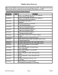
<strong>Vogt</strong> ® <strong>Tube</strong>-<strong>Ice</strong> ® MachineMID & LARGE MACHINE WARRANTY REGISTRATION/START-UP REPORTMUST COMPLETE AND RETURN TO INITIATE WARRANTYMachine Model No. ________________________________Serial No. ____________________________________________Installed at: ____________________________________________________________( )_______________________________________Company NamePhone_______________________________________________________________________________________________________Address City State Zip______________________________________________________________________________________________________Installed by: ___________________________________________________________( )________________________/____/________Company Name Phone Date_______________________________________________________________________________________________________Address City State ZipDescribe any damage to machine/repairs made: _________________________________________________________________________________________________________________________________________________________________________________________________________________________________________________________________________________________________________________Start up by: ___________________________________________________________( )________________________/____/_________Company Name Phone Date_______________________________________________________________________________________________________AddressName of person starting up machine: ____________________________________________________________________________________PRE START-UP CHECKCHECK<strong>Service</strong> <strong>Manual</strong> on h<strong>and</strong>Machine room suitable 50°F minimum, 110°F maximumProper power supply, actual voltage _______________, _________________, _________________ (machine not running)Compressor crankcase heater on 12 hour minimumNecessary h<strong>and</strong> valves opened as requiredSolenoid valve stems in auto positionSystem leak checked/tightAuxiliary equipment overloads wired into control circuitCompressor oil level _______ (1/4 glass min.)All water distributors in place (visually inspected)Water supply <strong>and</strong> drain lines installed <strong>and</strong> connected properlyCompressor, pump, cutter <strong>and</strong> other motor direction of rotation correctMake-up water float valve adjusted properlyHour meter in control panel connectedOPERATION CHECKMachine charged with refrigerant lbs.______________ Actual voltage ____________ , _______________, ________________(machine running)Ambient temp. _____ °F Fan cycles On _____ Off _____ Tower water in _____°F out ______ °FComp motor RLA _____________, _____________, _____________, Actual _____________, _____________, _____________,Pump RLA _____________, _____________, _____________, Actual _____________, _____________, _____________Cutter motor RLA _____________, _____________, _____________, Actual _____________, _____________, _____________Suction pressure end of freezing _______, end of harvest _______ Discharge pressure end of freezing ___________, end of harvest __________Evaporator/suction line frost _____________________________ Receiver liquid level operating ___________________TestCycle#1#2#3#4WaterTempFreezeTimeMin/SecHarvest TimeMin/SecFirst <strong>Ice</strong> OutMin/SecAll <strong>Ice</strong> OutMin/SecAvg. HoleSize<strong>Ice</strong> Lb. PerHarvest<strong>Ice</strong> Lb. PerDayNote: <strong>Ice</strong> lb. per day can be found by: ice lb. per harvest x 1440(freeze time + harvest time)The machine operated satisfactorily for ___ continuous hours. Date _______________________________________Comments____________________________________________________________________________________________________________________________________________________________________________________________________________________________Installer signature ____________________________________________ End user signature _________________________________Please return to: <strong>Tube</strong>-<strong>Ice</strong> Division, Henry <strong>Vogt</strong> Machine Co., 1000 W. Ormsby, Suite #135, Louisville, KY 40210
12/4/08
The Henry <strong>Vogt</strong> Machine Co., located inLouisville, Kentucky since 1880.Sales - (502) 635-3000<strong>Service</strong> - (502) 635-3247Parts - Your Local DistributorCall your local distributor first for all of your parts <strong>and</strong> service needs.Since 1938, Manufacturers of Quality<strong>Tube</strong>-<strong>Ice</strong> ® Machines
VOGT ®TUBE-ICE ® MACHINES<strong>P24ALOF</strong> & <strong>P34ALOF</strong> ModelHenry <strong>Vogt</strong> Machine Co.1000 W. Ormsby, Suite #135Louisville, Kentucky 40201-1918502-635-3000FAX #502-634-0479Installation, <strong>Service</strong> <strong>Manual</strong>, <strong>and</strong> Parts Catalog #12A-4171L1500000012/4/08
<strong>P24ALOF</strong> & <strong>P34ALOF</strong> <strong>Service</strong> <strong>Manual</strong>TABLE OF CONTENTS<strong>Vogt</strong> ® TUBE-ICE ® MACHINESModel <strong>P24ALOF</strong> & <strong>P34ALOF</strong>TABLE OF CONTENTSiPage No.1. INTRODUCTIONA Brief History Of Our Company .................................................................................................................................1-1<strong>Vogt</strong> Energy-Savings <strong>Tube</strong>-<strong>Ice</strong>® Machines ..................................................................................................................1-1Preview .....................................................................................................................................................................1-1Important Safety Notice.................................................................................................................................................1-2Safety Symbols <strong>and</strong> What They Mean ..........................................................................................................................1-2Special Precautions To Be Observed When Charging Refrigeration Systems ..............................................................1-3Assembly Drawing Model <strong>P24ALOF</strong> <strong>Tube</strong>-<strong>Ice</strong> ® Machine ............................................................................................1-4, 5, 6, 7Assembly Drawing Model <strong>P34ALOF</strong> <strong>Tube</strong>-<strong>Ice</strong> ® Machine ............................................................................................1-8, 9, 10, 112. RECEIPT OF YOUR TUBE-ICE MACHINEInspection .....................................................................................................................................................................2-1Description of Machine .................................................................................................................................................2-1Safety Tags <strong>and</strong> Labels..................................................................................................................................................2-1Model designation for P-Series <strong>Ice</strong> Machine, Figure 2-1 ..............................................................................................2-2Rated 2-2Storage (prior to installation <strong>and</strong> start-up) .....................................................................................................................2-23. INSTALLING YOUR TUBE-ICE MACHINEMachine Room ..............................................................................................................................................................3-1Space Requirements.......................................................................................................................................................3-1Foundation 3-1Lifting Procedures .........................................................................................................................................................3-1<strong>P24ALOF</strong> Space Diagram, FIGURE 3-1.......................................................................................................................3-2,3-3<strong>P24ALOF</strong> Foundation Layout, FIGURE 3-2.................................................................................................................3-4<strong>P34ALOF</strong> Space Diagram, FIGURE 3-3.......................................................................................................................3-5, 3-6<strong>P34ALOF</strong> Foundation Layout, FIGURE 3-4.................................................................................................................3-7Lifting Procedure for <strong>P24ALOF</strong>, FIGURE 3-5 .............................................................................................................3-8Lifting Procedure for <strong>P34ALOF</strong>, FIGURE 3-6 .............................................................................................................3-9Seismic Anchoring Detail, FIGURE 3-7 .......................................................................................................................3-10Water Supply, Drain <strong>and</strong> Refrigeration Connections, TABLE 3-1 ...............................................................................3-11Make-Up Water In,........................................................................................................................................................3-11Flushing Water In ..........................................................................................................................................................3-11Water Tank Drain ..........................................................................................................................................................3-12Water Tank Overflow....................................................................................................................................................3-12Receiver .....................................................................................................................................................................3-12Receiver Volume Requirements, TABLE 3-2 ...............................................................................................................3-12Page No.12/4/08
iiTABLE OF CONTENTS<strong>P24ALOF</strong> & <strong>P34ALOF</strong> <strong>Service</strong> <strong>Manual</strong>Thaw Gas Pressure Regulator........................................................................................................................................3-12Suction Pressure Regulator............................................................................................................................................3-12Compressor Unloading ..................................................................................................................................................3-12Cooling Tower (optional) ..............................................................................................................................................3-13Total Heat Rejection Requirements, TABLE 3-3..........................................................................................................3-13Safety Valves ................................................................................................................................................................3-14Freeze Protection, FIGURES 3-8, 3-9, 3-10..................................................................................................................3-14, 3-15Wiring <strong>and</strong> Electrical Connections.................................................................................................................................3-16Power Supply Connections, FIGURE 3-11 ....................................................................................................................3-16Voltage Unbalance .........................................................................................................................................................3-17Current Unbalance..........................................................................................................................................................3-17Rotation Check ...............................................................................................................................................................3-17Auxiliary Controls or Equipment ...................................................................................................................................3-18Interconnecting Piping for <strong>Vogt</strong> <strong>P24ALOF</strong> <strong>and</strong> Central High Side, FIGURE 3-12 ......................................................3-19Interconnecting Piping for <strong>Vogt</strong> <strong>P34ALOF</strong> <strong>and</strong> Central High Side, FIGURE 3-13 ......................................................3-20Interconnecting Piping for <strong>Vogt</strong> <strong>P34ALOF</strong> <strong>and</strong> Central High Side, Screw Compressor, FIGURE 3-14 .....................3-21Interconnecting Piping for 2-<strong>Vogt</strong> <strong>P34ALOF</strong> <strong>and</strong> Central High Side, FIGURE 3-15...................................................3-22Interconnecting Piping for 3-<strong>Vogt</strong> <strong>P34ALOF</strong> <strong>and</strong> Central High Side, FIGURE 3-16...................................................3-23Installation Reveiw: A Checklist ...................................................................................................................................3-244. HOW YOUR TUBE-ICE MACHINE WORKSOperating Features.........................................................................................................................................................4-1Liquid Overfeed Principle of Operation ........................................................................................................................4-1Freeze Period.................................................................................................................................................................4-1Harvest Period ...............................................................................................................................................................4-2Piping Nomenclature .....................................................................................................................................................4-2Piping Schematic for <strong>P24ALOF</strong>, FIGURE 4-1..............................................................................................................4-3Piping Schematic for <strong>P34ALOF</strong>, FIGURE 4-2..............................................................................................................4-45. START-UP AND OPERATIONRefrigeration System Review ........................................................................................................................................5-1Start-up Checklist ..........................................................................................................................................................5-2Refrigerant Charge ........................................................................................................................................................5-3Ammonia Specification By Grade, TABLE 5-1............................................................................................................5-3Special Precautions to be Observed when Charging Refrigeration Systems .................................................................5-3Charging From Tank Truck (for dedicated high side only) ...........................................................................................5-4Charging From Cylinders (for dedicated high side only) ..............................................................................................5-4Control Panel, FIGURE 5-1...........................................................................................................................................5-6Start-Up .....................................................................................................................................................................5-6Adding Refrigerant ........................................................................................................................................................5-7Operating Tips ...............................................................................................................................................................5-7Thaw Gas Regulating <strong>and</strong> Suction Regulating Valve Adjustment ................................................................................5-86. ELECTRICAL CONTROLS & THEIR FUNCTIONSPage No.
<strong>P24ALOF</strong> & <strong>P34ALOF</strong> <strong>Service</strong> <strong>Manual</strong>TABLE OF CONTENTSiiiBin Level Control ..........................................................................................................................................................6-1Safety Switches .............................................................................................................................................................6-1Control Panel (Door Opened), FIGURE 6-1..................................................................................................................6-2Description of Control Panel Parts (Inside), TABLE 6-1 ..............................................................................................6-2Control Panel (Door Closed), FIGURE 6-2...................................................................................................................6-3Description of Control Panel Parts (Outer Door), TABLE 6-2......................................................................................6-3Electrical Schematic All Voltages 50-60 Hz. Across Line Start, FIGURE 6-3 .............................................................6-47. MAINTENANCEPreventive Maintenance.................................................................................................................................................7-1Preventative Maintenance Form ....................................................................................................................................7-2<strong>Ice</strong>-Making Section........................................................................................................................................................7-3Cleaning Procedure........................................................................................................................................................7-3Water Distributors .........................................................................................................................................................7-3Water Distributors, TABLE 7-1 ....................................................................................................................................7-4Average Hole Size in <strong>Tube</strong>-<strong>Ice</strong> ® , TABLE 7-2...............................................................................................................7-4Water Tank ....................................................................................................................................................................7-4Water Cooled Condenser Cleaning (optional) ...............................................................................................................7-5Cooling Tower / Evap Condenser (optional) .................................................................................................................7-5Compressor (optional) ...................................................................................................................................................7-6Compressor Maintenance, TABLE 7-4 .........................................................................................................................7-7Oil Trap ....................................................................................................................................................................7-7Cutter Gear Reducer ......................................................................................................................................................7-78. TROUBLESHOOTINGList Of Symptoms..........................................................................................................................................................8-1Machine Stopped ...........................................................................................................................................................8-2, 8-3Freeze-Up Due To Extended Freezing Period ...............................................................................................................8-4Freeze-Up Due To <strong>Ice</strong> Failing To Discharge.................................................................................................................8-5Low <strong>Ice</strong> Capacity...........................................................................................................................................................8-6, 8-7Poor <strong>Ice</strong> Quality.............................................................................................................................................................8-7High Discharge Pressure................................................................................................................................................8-8Low Discharge Pressure ................................................................................................................................................8-9High Suction Pressure....................................................................................................................................................8-9Compressor Running Unloaded During Freeze .............................................................................................................8-9Compressor Oil Pressure Low .......................................................................................................................................8-10Compressor Loosing Oil Excessively............................................................................................................................8-10Machine Short Cycles....................................................................................................................................................8-11High Compressor Discharge Temperature.....................................................................................................................8-11Suction Line Frosting To Compressor...........................................................................................................................8-1112/4/08
ivTABLE OF CONTENTS<strong>P24ALOF</strong> & <strong>P34ALOF</strong> <strong>Service</strong> <strong>Manual</strong>Page No.9. SERVICE OPERATIONSAutomatic Blowdown (Harvest Cycle)..........................................................................................................................9-1Cleaning the <strong>Ice</strong> Making Section...................................................................................................................................9-1Float Valve (Make-Up Water).......................................................................................................................................9-1H<strong>and</strong> Expansion Valve ..................................................................................................................................................9-1Freeze Timer..................................................................................................................................................................9-1Minature Rocker Switch Settings for Freeze Timer ......................................................................................................9-2Entering <strong>and</strong> Displaying Setpoints ................................................................................................................................9-2Freeze Timer, FIGURE 9-2 ...........................................................................................................................................9-3Control Circuit Protection..............................................................................................................................................9-3Thawing Timer ..............................................................................................................................................................9-3Thawing Timer, FIGURE 9-4........................................................................................................................................9-4Suggested Condenser Cleaning .....................................................................................................................................9-4Cutter Gear Reducer ......................................................................................................................................................9-5Drive Gear Replacement................................................................................................................................................9-5Gear Reducer Replacement ...........................................................................................................................................9-6Water Tank <strong>and</strong> Cutter Parts Weights, TABLE 9-1 ......................................................................................................9-7Water Tank Removal.....................................................................................................................................................9-7Cutter Assembly Removal <strong>and</strong> Installation ...................................................................................................................9-8Bearing Bracket <strong>and</strong> Cutter Disc Removal....................................................................................................................9-8Cutter Shaft <strong>and</strong> Bearing Removal ................................................................................................................................9-9Cutter Shaft <strong>and</strong> Bearing Installation.............................................................................................................................9-9Cutter Height Adjustment..............................................................................................................................................9-11Water Tank Installation .................................................................................................................................................9-11P24A Cutter Assembly, FIGURE 9-5A.........................................................................................................................9-12P24A Water Tank Assembly, FIGURE 9-5B ................................................................................................................9-13P24A <strong>and</strong> P34A Cutter <strong>and</strong> Water Tank Part No., TABLE 9-2.....................................................................................9-14, 9-15Cutter Ring Gear Replacement......................................................................................................................................9-15Cutter Blade Replacement .............................................................................................................................................9-15Cutter Blade <strong>and</strong> Adapter Plate Adjustment, FIGURE 9-6 ...........................................................................................9-16Cutter Adapter Plate Installation....................................................................................................................................9-16Pumpdown 9-17Removal of Ammonia Refrigerant from the Machine ...................................................................................................9-17Refrigerant Leaks ..........................................................................................................................................................9-18Non-Condensable Gases................................................................................................................................................9-18Purging Non-Condensables ...........................................................................................................................................9-18Draining the Oil Trap ....................................................................................................................................................9-19Removing Excess Water from Ammonia ......................................................................................................................9-20Circulating Water Pump Motor .....................................................................................................................................9-21The Thaw Gas Solenoid Valve ......................................................................................................................................9-21Thaw Gas Solenoid Valve, FIGURE 9-7.......................................................................................................................9-22The Liquid Feed Solenoid Valve ...................................................................................................................................9-22Page No.
<strong>P24ALOF</strong> & <strong>P34ALOF</strong> <strong>Service</strong> <strong>Manual</strong>TABLE OF CONTENTSvThe Liquid Feed Solenoid Valve, FIGURE 9-8.............................................................................................................9-23The Thaw Chamber Check Valve..................................................................................................................................9-23The Thaw Chamber Check Valve, FIGURE 9-9 ...........................................................................................................9-23Water Flush Solenoid Valve..........................................................................................................................................9-24Compressor Oil Changing .............................................................................................................................................9-24Compressor Inspection ..................................................................................................................................................9-24Belt Tension...................................................................................................................................................................9-25Compressor Servicing....................................................................................................................................................9-2610. OPTIONS AND ACCESSORIESCrushed <strong>Ice</strong> Production .................................................................................................................................................10-2Length of <strong>Ice</strong> .................................................................................................................................................................10-2PLC (Programmable Logic Controller) ........................................................................................................................10-3Reduced Voltage Cutter Motor Starter ......................................................................................................................... 10-1311. TABLES AND CHARTS<strong>P24ALOF</strong> Specifications,TABLE 11-1 .........................................................................................................................11-2<strong>P34ALOF</strong> Specifications,TABLE 11-2 .........................................................................................................................11-3<strong>P24ALOF</strong> Make-up Water Usage, TABLE 11-3...........................................................................................................11-4<strong>P34ALOF</strong> Make-up Water Usage, TABLE 11-4...........................................................................................................11-4<strong>P34ALOF</strong> Liquid Feed Rates, TABLE 11-5 .................................................................................................................11-4<strong>P34ALOF</strong> Theoretical Pressure Drop though Evaporator, TABLE 11-6 ......................................................................11-4Recommended Spare Parts List .....................................................................................................................................11-6Temperature - Pressure Chart for Common Refrigerants, TABLE 11-7 .......................................................................11-7Conversion Factors: English to Metric, TABLE 11-8 ...................................................................................................11-8Constants, TABLE 11-9 ................................................................................................................................................11-812. APPENDIX12/4/08
viTABLE OF CONTENTS<strong>P24ALOF</strong> & <strong>P34ALOF</strong> <strong>Service</strong> <strong>Manual</strong>
<strong>P24ALOF</strong> & <strong>P34ALOF</strong> <strong>Service</strong> <strong>Manual</strong>1-1INTRODUCTION1. IntroductionHenry <strong>Vogt</strong> Machine Co.A Brief History Of Our Company. Henry <strong>Vogt</strong> Machine Co. was founded as a small machineshop in Louisville, Kentucky in 1880. Today, it is one of the world’s leading producers of icemakingequipment.In 1938, <strong>Vogt</strong> built the first <strong>Tube</strong>-<strong>Ice</strong> ® machine <strong>and</strong> revolutionized the ice-making industry. Ourfirst “sized-ice” machine quickly replaced the old can-ice plants, which required hard labor <strong>and</strong> largeamounts of floor space for freezing, cutting, <strong>and</strong> crushing ice by h<strong>and</strong>.<strong>Vogt</strong> Energy-Saving <strong>Tube</strong>-<strong>Ice</strong> Machines Are Cost Effective. Today, <strong>Vogt</strong> <strong>Tube</strong>-<strong>Ice</strong> ® machinesenjoy a well-earned reputation as the most energy efficient, dependable ice-making equipment in theworld.Using as little as one-half to one-third the energy required by competitors’ ice makers, <strong>Tube</strong>-<strong>Ice</strong> ®machines produce the same amount of ice--in restaurants, sports arenas, packing plants, <strong>and</strong>wholesale operations around the globe--at great savings.In addition, <strong>Tube</strong>-<strong>Ice</strong> ® machines are renowned for their long life, giving many customers more than35 years of dependable service. Ask someone who owns one.Preview. All the skill in engineering <strong>and</strong> fabrication that we’ve learned in over a century ofexperience is reflected in every <strong>Tube</strong>-<strong>Ice</strong> ® machine. Since <strong>Vogt</strong> introduced <strong>Tube</strong>-<strong>Ice</strong> ® machines in1938, the process of making <strong>Tube</strong>-<strong>Ice</strong> ® ice has been widely recognized as the most economicalmeans of production. The machine’s economic <strong>and</strong> reliable operation has been proven over <strong>and</strong>over again, in a network of varied types of installations throughout the world.This manual is designed to assist you in the installation, start-up, <strong>and</strong> maintenance of your unit.Your <strong>Tube</strong>-<strong>Ice</strong> ® machine will give you a lifetime of service provided you install, maintain, <strong>and</strong>service it properly. It is evidence of our desire to deliver to you “the finest ice-making unit evermade.”Please read your manual carefully before attempting installation, operation, or servicing of thisprofessionally-designed piece of equipment. Also, make sure the Warranty Registration/Start-upReport is completed <strong>and</strong> returned.If you have additional questions, please call your distributor. Also, feel free to phone the factorydirect at (502) 635-3000.12/4/08
1-2INTRODUCTION<strong>P24ALOF</strong> & <strong>P34ALOF</strong> <strong>Service</strong> <strong>Manual</strong>Important Safety Notice. This information is intended for use by individuals possessing adequatebackgrounds in electrical, refrigeration <strong>and</strong> mechanical experience. Any attempt to repair majorequipment may result in personal injury <strong>and</strong>/or property damage. The manufacturer or seller cannotbe responsible for the interpretation of this information, nor can it assume any liability in connectionwith its use. It is important that personnel underst<strong>and</strong> the properties of this refrigerant <strong>and</strong> that theybe thoroughly trained in safe practices for its use <strong>and</strong> h<strong>and</strong>ling. Refer to the enclosed “AnhydrousAmmonia Safety” in Appendix A.Safety Symbols & What They Mean. Prior to installation or operation of the <strong>Tube</strong>-<strong>Ice</strong> ® machine,please read this manual. Are you familiar with the installation, start-up, <strong>and</strong> operation of a <strong>Tube</strong>-<strong>Ice</strong> ® machine? Before you operate, adjust or service this machine, you should read this manual,underst<strong>and</strong> the operation of this machine, <strong>and</strong> be aware of possible dangers.These safety symbols will alert youwhen special care is needed.Please heed them.! DANGER !Indicates an immediate hazard <strong>and</strong> that special precautionsare necessary to avoid severe personal injury or death.! DANGER !! WARNING !Indicates a strong possibility of a hazard <strong>and</strong> that anunsafe practice could result in severe personal injury.! WARNING !! CAUTION !Means hazards or unsafe practices could resultin personal injury or product or property damage.! CAUTION !12/4/08
<strong>P24ALOF</strong> & <strong>P34ALOF</strong> <strong>Service</strong> <strong>Manual</strong>1-3INTRODUCTIONSpecial Precautions To Be Observed When Charging Refrigeration Systems. Only technicallyqualifiedpersons, experienced <strong>and</strong> knowledgeable in the h<strong>and</strong>ling of anhydrous ammonia refrigerant<strong>and</strong> operation of refrigeration systems, should perform the operations described in this manual. Alllocal, federal, <strong>and</strong> EPA regulations must be strictly adhered to when h<strong>and</strong>ling ammonia (R-717)refrigerant. See “Material Safety Data Sheet”, MSDS Code No. 5B81-83.If a refrigeration system is being charged from refrigerant cylinders, disconnect each cylinder whenempty or when the system is fully charged. A gage should be installed in the charging line toindicate refrigerant cylinder pressure. The cylinder may be considered empty of liquid R-717refrigerant when the gauge pressure is 25 pounds or less, <strong>and</strong> there is no frost on the cylinder. Closethe refrigerant charging valve <strong>and</strong> cylinder valve before disconnecting the cylinder. Loosen theunion in the refrigerant charging line--carefully to avoid unnecessary, excessive or illegal release ofrefrigerant into the atmosphere.! CAUTION !Immediately close system charging valve at commencement of defrost or thawing cycle ifrefrigerant cylinder is connected. Never leave a refrigerant cylinder connected to systemexcept during charging operation. Failure to observe either of these precautions can result intransferring refrigerant from the system to the refrigerant cylinder, over-filling it, <strong>and</strong>possibly causing the cylinder to rupture because of pressure from expansion of the liquidrefrigerant brought on by an increase in temperature.! CAUTION !Always store cylinders containing refrigerant in a cool place. They should never be exposed totemperatures higher than 120°F <strong>and</strong> should be stored in a manner to prevent abnormal mechanicalshocks.Also, transferring refrigerant from a refrigeration system into a cylinder can be very dangerous <strong>and</strong>is not recommended.! CAUTION !It is not recommended that refrigerant be transferred from a refrigeration system directly intoa cylinder. If such a transfer is made, the refrigerant cylinder must be an approved, CLEANcylinder--free of any contaminants or foreign materials--<strong>and</strong> must be weighed continuously toassure contents do not exceed net weight specified by cylinder manufacturer or any applicablecode requirements.! CAUTION !12/4/08
1-4INTRODUCTION<strong>P24ALOF</strong> & <strong>P34ALOF</strong> <strong>Service</strong> <strong>Manual</strong>FIGURE 1-1<strong>P24ALOF</strong> 1” Front Side (Control Panel)12/4/08
<strong>P24ALOF</strong> & <strong>P34ALOF</strong> <strong>Service</strong> <strong>Manual</strong>1-5INTRODUCTIONFIGURE 1-2<strong>P24ALOF</strong> Right Side12/4/08
1-6INTRODUCTION<strong>P24ALOF</strong> & <strong>P34ALOF</strong> <strong>Service</strong> <strong>Manual</strong>FIGURE 1-3<strong>P24ALOF</strong> Back Side12/4/08
<strong>P24ALOF</strong> & <strong>P34ALOF</strong> <strong>Service</strong> <strong>Manual</strong>1-7INTRODUCTIONFIGURE 1-4<strong>P24ALOF</strong> Left Side12/4/08
1-8INTRODUCTION<strong>P24ALOF</strong> & <strong>P34ALOF</strong> <strong>Service</strong> <strong>Manual</strong>FIGURE 1-5<strong>P34ALOF</strong> Front Side (Control Panel)12/4/08
<strong>P24ALOF</strong> & <strong>P34ALOF</strong> <strong>Service</strong> <strong>Manual</strong>1-9INTRODUCTIONFIGURE 1-6<strong>P34ALOF</strong> Right Side12/4/08
1-10INTRODUCTION<strong>P24ALOF</strong> & <strong>P34ALOF</strong> <strong>Service</strong> <strong>Manual</strong>FIGURE 1-7<strong>P34ALOF</strong> Back Side12/4/08
<strong>P24ALOF</strong> & <strong>P34ALOF</strong> <strong>Service</strong> <strong>Manual</strong>1-11INTRODUCTIONFIGURE 1-8<strong>P34ALOF</strong> Left Side12/4/08
1-12INTRODUCTION<strong>P24ALOF</strong> & <strong>P34ALOF</strong> <strong>Service</strong> <strong>Manual</strong>12/4/08
<strong>P24ALOF</strong> & <strong>P34ALOF</strong> <strong>Service</strong> <strong>Manual</strong>2-1RECEIPT OF YOUR TUBE-ICE MACHINE2. Receipt Of Your <strong>Tube</strong>-<strong>Ice</strong> Machine! CAUTION !Only service personnel experienced in ammonia refrigeration <strong>and</strong>qualified to work on high amperage electrical equipment shouldbe allowed to install or service this <strong>Tube</strong>-<strong>Ice</strong> ® machine.Eye protection should be worn by all personnelworking on or around the <strong>Tube</strong>-<strong>Ice</strong> ® machine.It is very important that you are familiar with <strong>and</strong> adhere toall local, state, <strong>and</strong> federal, etc. ordinances <strong>and</strong> laws regardingthe h<strong>and</strong>ling, storing, <strong>and</strong> use of anhydrous ammonia.An approved ammonia mask should be readily availablefor use in an emergency <strong>and</strong> all personnel should be awareof its location <strong>and</strong> proper use.! CAUTION !Inspection. As soon as you receive your machine, inspect it for any damage. If damage issuspected, note it on the shipper’s papers (i.e., the trucker’s Bill of Lading). Immediately make aseparate written request for inspection by the freight line’s agent. Any repair work or alteration tothe machine without the permission of the Henry <strong>Vogt</strong> Machine Co. can void the machine’swarranty. You should also notify your <strong>Vogt</strong> distributor or the factory.Description Of Machine. A <strong>Vogt</strong> low side <strong>Tube</strong>-<strong>Ice</strong> ® machine is a remote ice producing plantrequiring refrigerant suction connection, refrigerant liquid connection, thaw gas connection, makeupwater supply, electrical connection, <strong>and</strong> the proper refrigerant charge.The machine has been partially factory tested prior to shipment <strong>and</strong> will require adjustment to meetthe high side (condenser unit) operating conditions. See Start-up <strong>and</strong> Operation for the correctsetting of the controls.After factory pressure testing of the machine, the machine is evacuated <strong>and</strong> charged with nitrogengas pressure for shipment. This prevents air or moisture from entering the system during transit.There should be a positive pressure (20-25 psig) indicated on the control panel gages when themachine is received. The machine has been cleaned with ice machine cleaner <strong>and</strong> flushed so that themachine is ready for ice production.Safety Tags <strong>and</strong> Labels. Be sure to read <strong>and</strong> adhere to all special tags <strong>and</strong> labels attached to valvesor applied to various areas of the machine. They provide important information necessary for safe<strong>and</strong> efficient operation of your equipment.The machine is available in three different tube sizes for producing ice 7/8” OD x 1” long, 1 1/8”OD x 1” long, or 1 3/8” OD x 1” long. The ice is cut to length by a rotating breaker type cutter. <strong>Ice</strong>can be produced up to 1 1/2” long by modifying the spacers under the adapter plates (see Chapter10, “<strong>Ice</strong> Length” for modifying instructions). Crushed ice is also available by modifying the cutter<strong>and</strong> making minor adjustments to the machine (see Chapter 10, “Crushed <strong>Ice</strong>”).12/4/08
2-2RECEIPT OF YOUR TUBE-ICE MACHINE<strong>P24ALOF</strong> & <strong>P34ALOF</strong> <strong>Service</strong> <strong>Manual</strong>FIGURE 2-1Model Designation for P-Series <strong>Ice</strong> MachinesRated Capacity. The <strong>Tube</strong>-<strong>Ice</strong> ® machine is rated to produce a given amount of ice when operatingunder the proper conditions as specified in this manual (see Section 11 for the operatingspecifications). You should be prepared to h<strong>and</strong>le the ice produced as it is discharged from themachine <strong>and</strong> move it to your storage or bagging area promptly.Storage (prior to installation or start-up). The machine must not be stored or installed in an areathat is subject to reach temperatures at or above 110°F (43.3°C).12/4/08
<strong>P24ALOF</strong> & <strong>P34ALOF</strong> <strong>Service</strong> <strong>Manual</strong>INSTALLING YOUR TUBE-ICE MACHINE3-13. Installing Your <strong>Tube</strong>-<strong>Ice</strong> MachineYour machine will be shipped to you as one package. You will need to arrange for the h<strong>and</strong>ling ofthe package as soon as it arrives, see the machine specifications Section 11 for shipping <strong>and</strong>operating weight. Before you remove the unit from the truck, be certain that any sign of damage,however slight, is noted on the carrier’s papers.Note: See “Lifting Procedure” drawing furnished with this manual, Fig 3-5 <strong>and</strong> 3-6.Machine Room. The machine must be located inside a suitable building <strong>and</strong> must not be subjectedto ambient temperatures below 50°F (10°C) or above 110°F (43.3°C). Heat radiation from othersources (sunlight, furnaces, condenser, etc.) <strong>and</strong> unusual air current may affect the operation of themachine <strong>and</strong> should be avoided. The electrical components of the <strong>Tube</strong>-<strong>Ice</strong> ® machine are ratedNEMA 1. Therefore, the machine should not be located in a hazardous area or sprayed withwater. The machine should be installed in an area where water will not st<strong>and</strong>, but will readily drainaway from the machine.Space Requirements. Refer to the space diagrams, Figures 3-1 <strong>and</strong> 3-3, for recommendedminimum clearance around the machine for ease of servicing <strong>and</strong> observation. Pay particularattention to the additional space required. If it ever becomes necessary to mechanically clean thefreezer tubes, extra space will be required.Foundation. Refer to the space diagrams, Figures 3-2 <strong>and</strong> 3-4, for recommended minimumfoundation requirements. The figures show anchor bolt details <strong>and</strong> machine anchor hole details.Contact your local distributor for seismic anchoring requirements in your area.! WARNING !Lifting or moving heavy equipment should only be attempted bycompetent rigging <strong>and</strong> hoisting contractors. Never allow personnelnear or under heavy equipment when it is being moved or lifted.Failure to comply could result in personal injury or loss of life.! WARNING !Lifting Procedures. Your <strong>Tube</strong>-<strong>Ice</strong> ® machine is provided with lifting lugs for the purpose ofunloading <strong>and</strong> moving the machine to its operation location. Refer to the enclosed drawings forinstructions <strong>and</strong> illustrations of their use.<strong>P24ALOF</strong>- Figure 3-5. Machine weight 6,200 lbs.<strong>P34ALOF</strong>- Figure 3-6. Machine weight 9,800 lbs.These figures are intended as a guide to unloading <strong>and</strong> lifting the <strong>P24ALOF</strong> <strong>and</strong> <strong>P34ALOF</strong> <strong>Tube</strong>-<strong>Ice</strong> ® machine. The <strong>Vogt</strong> <strong>Tube</strong>-<strong>Ice</strong> LLC is not responsible for product damage or personnelinjury or loss of life during the loading or lifting procedure.12/4/08
3-2INSTALLING YOUR TUBE-ICE MACHINE<strong>P24ALOF</strong> & <strong>P34ALOF</strong> <strong>Service</strong> <strong>Manual</strong>FIGURE 3-1A<strong>P24ALOF</strong> Space Diagram (Front View)12/4/08
<strong>P24ALOF</strong> & <strong>P34ALOF</strong> <strong>Service</strong> <strong>Manual</strong>INSTALLING YOUR TUBE-ICE MACHINE3-3FIGURE 3-1B<strong>P24ALOF</strong> Space Diagram (Side View)12/4/08
3-4INSTALLING YOUR TUBE-ICE MACHINE<strong>P24ALOF</strong> & <strong>P34ALOF</strong> <strong>Service</strong> <strong>Manual</strong>FIGURE 3-2<strong>P24ALOF</strong> Foundation Layout12/4/08
<strong>P24ALOF</strong> & <strong>P34ALOF</strong> <strong>Service</strong> <strong>Manual</strong>INSTALLING YOUR TUBE-ICE MACHINE3-5FIGURE 3-3A<strong>P34ALOF</strong> Space Diagram (Front View)12/4/08
3-6INSTALLING YOUR TUBE-ICE MACHINE<strong>P24ALOF</strong> & <strong>P34ALOF</strong> <strong>Service</strong> <strong>Manual</strong>FIGURE 3-3B<strong>P34ALOF</strong> Space Diagram (Side View)12/4/08
<strong>P24ALOF</strong> & <strong>P34ALOF</strong> <strong>Service</strong> <strong>Manual</strong>INSTALLING YOUR TUBE-ICE MACHINE3-7FIGURE 3-4<strong>P34ALOF</strong> Foundation Layout12/4/08
3-8INSTALLING YOUR TUBE-ICE MACHINE<strong>P24ALOF</strong> & <strong>P34ALOF</strong> <strong>Service</strong> <strong>Manual</strong>FIGURE 3-5Lifting Procedure for <strong>P24ALOF</strong>12/4/08
<strong>P24ALOF</strong> & <strong>P34ALOF</strong> <strong>Service</strong> <strong>Manual</strong>INSTALLING YOUR TUBE-ICE MACHINE3-9FIGURE 3-6Lifting Procedure for <strong>P34ALOF</strong>12/4/08
3-10INSTALLING YOUR TUBE-ICE MACHINE<strong>P24ALOF</strong> & <strong>P34ALOF</strong> <strong>Service</strong> <strong>Manual</strong>FIGURE 3-7Seismic Anchoring Detail for <strong>P24ALOF</strong> <strong>and</strong> <strong>P34ALOF</strong> <strong>Tube</strong>-<strong>Ice</strong> Machines12/4/08
<strong>P24ALOF</strong> & <strong>P34ALOF</strong> <strong>Service</strong> <strong>Manual</strong>INSTALLING YOUR TUBE-ICE MACHINE3-11Piping <strong>and</strong> Drain Connections. See Figure 1-1 to 1-8 <strong>and</strong> 3-11 to 3-17 for connection locations.When connecting refrigeration piping, you must follow <strong>and</strong> adhere to all ANSI/ASHRAE 15 “Safety Code for Mechanical Refrigeration” <strong>and</strong> ANSI St<strong>and</strong>ard B-31.5 “ Refrigeration PipingCode”. Also, all piping must conform to all state <strong>and</strong> local codes. Make sure all piping is keptclean, dry <strong>and</strong> contaminate free. All piping should be supported properly.! CAUTION !Exterior shut-off valves must be provided in the waterinlet lines. The minimum inlet water pressure forsatisfactory operation of the machine is 40 psig.The maximum allowable pressure is 100 psig.! CAUTION !ModelMake-upWater InFlushingWater In<strong>P24ALOF</strong> 3/4” FPT 3/4” FPT72 gal/3 min.<strong>P34ALOF</strong> 1” FPT 3/4” FPT104 gal/3 min.* Mating 4 bolt flange supplied with machine.** Liquid connection is all purpose coupling.WaterTankDrainWaterTankOverflowLow SideSuctionConnection*2” FPT 3” FPT 4” SWFlange2” FPT 3” FPT 6” SWFlangeLow SideLiquidConnection**Low SideThaw GasConnection1” FPT or SW 2” SWFlange1 1/4” FPT or 2” SWSWFlangeTABLE 3-1Water Supply, Drain <strong>and</strong> Refrigeration Connections(See FIGURE 1-1 through 1-8 for locations)Make-Up Water In. The water required for ice making must be potable water, safe for humanconsumption, <strong>and</strong> should be of the highest quality available. The best way to determine waterquality is to have a complete water quality analysis by a qualified laboratory.It is advisable to install a particle filter in the make-up <strong>and</strong> flushing water lines to trap dirt, s<strong>and</strong>,rust, or other solid particles prior to entering the water tank <strong>and</strong> contaminating the ice. Be sure tosize the filter large enough to meet the water dem<strong>and</strong>s of 15 GPM (peak flow), allowing for arestriction through the filter as it traps these particles. The inlet water pressure should be a minimumof 40 psi. Refer to TABLE 3-1 for line size <strong>and</strong> Section 11 for average flow rate at various watertemperatures.Flushing Water In. Flushing water (blowdown) is necessary to melt ice fines <strong>and</strong> flush dissolvedsolids from the water tank during the thawing (harvest) cycle. This function is important <strong>and</strong> helpsto maintain good ice quality. If water quality is superior, installing a smaller orifice in the flushingoutlet elbow can reduce this blowdown. Make sure there is enough flushing water to prevent theaccumulation of excessive ice fines in the tank.If make-up <strong>and</strong> flushing water are from the same source, a common line to the machine can connectthem.12/4/08
3-12INSTALLING YOUR TUBE-ICE MACHINE<strong>P24ALOF</strong> & <strong>P34ALOF</strong> <strong>Service</strong> <strong>Manual</strong>Water Tank Drain. This valve <strong>and</strong> connection is for the purpose of flushing <strong>and</strong> draining the watertank of impurities, foreign material <strong>and</strong> cleaning chemicals used during servicing. It should be pipedto an open drain or sump for visible discharge. It can be tied in with the overflow line but no others.Water Tank Overflow. A 3” FPT connection on the side of the water tank is provided to carryaway overflow water during the thawing (harvest cycle). This water contains ice fines accumulatedduring harvesting <strong>and</strong> dissolved solids accumulated during the freezing cycle. Do not reduce thesize of this line. Three inches is needed to provide sufficient area for ice fines to be flushed out,especially if the incoming flushing water is 55°F (13°C) or below. This overflow line should not tiein with any other drain line except the water tank drain.Unless water quality is superior, do not discharge the overflow water to the cooling tower system.This water contains additional dissolved solids left from the ice making process <strong>and</strong> can lead toexcessive condenser fouling or cooling tower chemical usage. It is recommended that a heatexchanger be used in place of direct contact with condenser water.Receiver. The receiver used to supply hot thaw gas must be sized adequately to provide suffecientthaw gas. Table 3-2 shows the volume required to hold the refrigeration charge of the freezer <strong>and</strong>the hot gas required for the thaw cycle. It is recommended that a heating coil be installed in thereceiver to assure that the liquid ammonia is at saturated temperature at the start of each thaw period.Note: Additional storage volume may be required for the interconnecting piping. Add volume ofinterconnecting piping to the values shown in Table 3-2RECEIVER VOLUME (Cubic Feet)MODEL With Heating Coil With out Heating Coil<strong>P24ALOF</strong> 30 45<strong>P34ALOF</strong> 50 70TABLE 3-2Receiver Volume RequirementsThaw Gas Pressure Regulator. The thaw gas pressure regulator is a 2” solenoid operated pressurecombination regulator <strong>and</strong> shut-off valve (see figures 1-2 <strong>and</strong> 1-5 for locations). Do not reduce thesize of this line. This valve is deigned to carry the proper amount of thaw gas to the evaporatorduring the harvest cycle. See section 5-7 for operating instructions.Suction Pressure Regulator. When a <strong>P24ALOF</strong> or <strong>P34ALOF</strong> is attached to a central system a nevaporator pressure regulator will be required (see Figures 3-15 through 3-16 for location). Thisregulator (usually furnished by the purchaser) must be a combination back-pressure regulating <strong>and</strong>open type valve. The usual minimum pressure drop across this type valve is 2 psig, therefore thevalve must be set to maintain a freezer pressure at least 2 psi above the maximum general suctionpressure. A throttling by-pass line with a solenoid shut-off <strong>and</strong> h<strong>and</strong> valve for regulating flowshould accompany this valve.Compressor Unloading. When multiple <strong>P24ALOF</strong>’s or <strong>P34ALOF</strong>’s are attached to a dedicatedcompressor system unloading of the compressor may be required. A minimum compressorunloading during the harvest cycle is 50%. If the compressor can not be unloaded then a hot gasbypass to the suction line must be installed. See Figures 3-12 <strong>and</strong> 3-13.12/4/08
<strong>P24ALOF</strong> & <strong>P34ALOF</strong> <strong>Service</strong> <strong>Manual</strong>INSTALLING YOUR TUBE-ICE MACHINE3-13Cooling Tower (optional). When selecting a cooling tower, careful attention must be given tooperating wet bulb conditions. It is advisable to check with your local cooling tower distributor fortheir recommendations based on actual operating conditions in your area. An average wet bulb of78°F is typical in the U.S., but many localities have designed wet bulbs as low as 72°F or as high as82°F.The cooling tower water pump must be capable of delivering the required volume of water throughthe condenser. Due to cooling tower location <strong>and</strong> pressure drop through water lines <strong>and</strong> regulatingvalves, the water pump must be sized for each installation. Table 3-2 shows the total heat rejection,in 1000 BTU’s per hour for the <strong>P24ALOF</strong> <strong>and</strong> <strong>P34ALOF</strong> at different suction temperatures. Thewater piping for the cooling tower <strong>and</strong> the installation of the pump must be in accordance with themanufacturer’s instructions. Caution must be used to prevent the condenser water pump from losingit’s prime during off cycles.Proper water treatment for the prevention of mineral <strong>and</strong> foreign matter accumulation in thecondenser or cooling tower is recommended. A water analysis should be obtained to determine theproper chemicals to use. The use of a 40 mesh strainer in the condenser water supply line is alsorecommended.<strong>P24ALOF</strong> - Cylinder<strong>P34ALOF</strong> - CylinderSuctionTemperature °F / °C1”<strong>Tube</strong>1 1/4”<strong>Tube</strong>1 1/2”<strong>Tube</strong>1”<strong>Tube</strong>1 1/4”<strong>Tube</strong>1 1/2”<strong>Tube</strong>21.4 /-6.0 603 552 385 1229 1127 80116.6 /-8.5 995 916 649 1987 1840 133911.3 /-11.5 1526 1414 1022 2991 2796 20865.5 /-15.7 2260 2111 1559 4350 4111 3146-1.0 /-18.3 3337 3147 2380 6308 6039 4749<strong>P24ALOF</strong> - Crushed<strong>P34ALOF</strong> - Crushed21.4 /-6.0 778 827 734 1544 1623 146316.6 /-8.5 1246 1314 1185 2414 2521 231111.3 /-11.5 1854 1943 1780 3515 3655 34035.5 /-15.7 2662 2776 2581 4952 5137 4850-1.0 / -18.3 3808 3959 3734 6963 7217 6905Total Heat Rejection is based on pulldown of 105°F SDT <strong>and</strong> are nominal values based onopen drive reciprocating compressor.Consult factory for condenser sizing if desired.TABLE 3-3Total Heat Rejection (MBH)The condenser water pump should be sized on GPM required for condenser at 80-ft. total dischargehead for a typical installation. However, due to cooling tower location <strong>and</strong> pressure drop throughwater lines, the water pump should be sized for each installation.12/4/08
3-14INSTALLING YOUR TUBE-ICE MACHINE<strong>P24ALOF</strong> & <strong>P34ALOF</strong> <strong>Service</strong> <strong>Manual</strong>If the condenser inlet water temperature is expected to be below 75°F/24°C, a water-regulating valveshould be installed in the condenser water outlet line <strong>and</strong> adjusted to maintain a head pressure of notless than 175 psig.See FIGURES 3-5 through 3-8 for possible cold climate installations with indoor sump.Safety Valves. Two safety pressure relief valves are an integral part of the <strong>Tube</strong>-<strong>Ice</strong> ® machine.They are located on the suction accumulator of the freezer. Vent each of the pressure relief valves tothe atmosphere in such a manner as to comply with local <strong>and</strong> national codes. Refer to theInternational Institute of Ammonia Refrigeration (IIAR) st<strong>and</strong>ard for specific requirements <strong>and</strong>instructions.COOLING TOWERWATERCOOLEDCONDENSERCHECK VALVEINDOOR SUMPFIGURE 3-81 PUMP/2-WAY VALVE* Poor Freeze ProtectionBecause low flow rate = high freeze chance12/4/08
<strong>P24ALOF</strong> & <strong>P34ALOF</strong> <strong>Service</strong> <strong>Manual</strong>INSTALLING YOUR TUBE-ICE MACHINE3-15COOLING TOWERWATERCOOLEDCONDENSEROnly enough water tomaintain head pressureSame flow rateto cooling towerCHECK VALVEINDOOR SUMPFIGURE 3-91 PUMP/3-WAY VALVE* Better Freeze ProtectionCOOLING TOWERWATERCOOLEDCONDENSERCHECK VALVEINDOOR SUMPOutdoor pump is off untilindoor sump needs coolingFIGURE 3-102 PUMP/2-WAY VALVE* Best Freeze Protection12/4/08
3-16INSTALLING YOUR TUBE-ICE MACHINE<strong>P24ALOF</strong> & <strong>P34ALOF</strong> <strong>Service</strong> <strong>Manual</strong>Wiring <strong>and</strong> Electrical Connections.! WARNING !Only service personnel experienced in refrigeration <strong>and</strong> qualifiedto work with high voltage electrical equipment should be allowedto install or work with the <strong>Tube</strong>-<strong>Ice</strong> ® machine.! WARNING !A fused disconnect must be provided near the <strong>Tube</strong>-<strong>Ice</strong> ® machine. The control panel <strong>and</strong>transformer (if required) are attached to the structurals on the front of the <strong>Tube</strong>-<strong>Ice</strong> ® machine (seeFIGURE 3-11). Incoming 3-phase power will be connected at the cutter motor circuit breaker(CB3). Terminals L1, L2, L3 for operation of the <strong>Tube</strong>-<strong>Ice</strong> ® machine <strong>and</strong> its controls. Rotationchecking of the, cutter motor, <strong>and</strong> water pump <strong>and</strong> auxiliary equipment is required (see rotationcheck). Also, if one leg of the 3-phase power is higher or lower (“wild”), then it should beconnected to terminal L3. Connect the ground wire to the “ground” terminal provided.Make sure wires #22 <strong>and</strong> #27 are connected to the elapse time (ET) indicator in the control panel.FIGURE 3-11Power Supply Connections12/4/08
<strong>P24ALOF</strong> & <strong>P34ALOF</strong> <strong>Service</strong> <strong>Manual</strong>INSTALLING YOUR TUBE-ICE MACHINE3-17Voltage Unbalance Voltage unbalance can cause motors to overheat <strong>and</strong> fail. Voltage imbalancebetween any two legs should be no greater than 2%.Example: Supply voltage = 230-3-60Voltage Readings: AB = 220 VoltsBC = 225 VoltsAC = 227 VoltsAverage = (220 + 225 + 227)/3 = 224 Volts(AB) 224-220 = 4 Volts (Highest Deviation)(BC) 225-224 = 1 Volts(AC) 227-224 = 3 Volts% Voltage Unbalance = 100 x (4/224) = 1.78% “Acceptable”Important: If the supply voltage phase unbalance is more the 2%, contact your localelectric utility company.Current Unbalance Voltage unbalance will cause a current unbalance, but a current unbalancedoes not necessarily mean that a voltage unbalance exists. A loose terminal connection or a buildupof dirt or carbon on one set of contacts would cause a higher resistance on that leg than on the othertwo legs. Current follows the path of least resistance, therefore if terminal connection L1 is loose ordirty, L2 <strong>and</strong>/or L3 will have higher current.Higher current causes more heat to be generated in the motor windings. The maximum acceptablecurrent unbalance is 10%.Example:Current Readings:L1 = 96 AmpsL2 = 91 AmpsL3 = 98 AmpsAverage = (96 + 91 + 98)/3 = 95Amps(L1) 96-95 = 1 Amps(L2) 95-91 = 4 Amps (Highest Deviation)(L3) 98-95 = 3 Amps% Current Unbalance = 100 x (4/95) = 4.2% “Acceptable”Rotation Check. The compressor, cutter, <strong>and</strong> pump motor rotation are factory synchronized, butmust be checked at installation. For cylinder ice production, the cutter disc as viewed at the icedischarge opening should turn from left to right.Check rotation by the following procedure:12/4/081. Turn the power to the machine on <strong>and</strong> check voltages.2. Make sure the water tank is full of clean water.3. Turn the H<strong>and</strong>-Auto switch (ISS) to HAND position. The water pump will start <strong>and</strong> the freezing(1LT) <strong>and</strong> the liquid feed (2LT) pilot lights will illuminate. Check pump rotation.4. Push the MANUAL HARVEST button. The water pump will stop, the “Freezing <strong>and</strong> LiquidFeed” lights will go out, <strong>and</strong> after 20-30 seconds, the cutter motor will start. The thawing gassolenoid valve will open <strong>and</strong> the “Thawing” pilot light (3LT) will illuminate.
3-18INSTALLING YOUR TUBE-ICE MACHINE<strong>P24ALOF</strong> & <strong>P34ALOF</strong> <strong>Service</strong> <strong>Manual</strong>5. Check the cutter disc rotation. It should be turning from left to right (CCW looking from thetop).6. Turn the HAND-AUTO switch to AUTO to stop the cutter.To change rotation, follow this procedure:1. Disconnect power to the machine <strong>and</strong> lock it out to make sure it can’t be turned back on.2. Check for power at L1, L2, L3 with a volt meter to make sure it is off.3. At the cutter motor circuit breaker (CB3) or at the power disconnect, reverse wires L1 <strong>and</strong> L2.4. Make sure these terminals are tight <strong>and</strong> restore power to the machine.5. Perform rotation check again to confirm that it is correct.! CAUTION !Do not attempt to start the machine until first making sure allconditions listed in the Installation Review Checklist <strong>and</strong> allnecessary valves have been opened for operation.! CAUTION !Auxiliary Controls or Equipment. When connecting other equipment such as high/low pressureswith, conveyor motors, bin level control, etc., refer to the control panel wiring drawing for theproper connecting terminals <strong>and</strong> instructions. See Figure 6-3.12/4/08
<strong>P24ALOF</strong> & <strong>P34ALOF</strong> <strong>Service</strong> <strong>Manual</strong>INSTALLING YOUR TUBE-ICE MACHINE3-19FIGURE 3-12Interconnecting Piping for <strong>Vogt</strong> <strong>P24ALOF</strong> <strong>and</strong> Central High Side12/4/08
3-20INSTALLING YOUR TUBE-ICE MACHINE<strong>P24ALOF</strong> & <strong>P34ALOF</strong> <strong>Service</strong> <strong>Manual</strong>FIGURE 3-13Interconnecting Piping for <strong>Vogt</strong> <strong>P34ALOF</strong> <strong>and</strong> Central High Side12/4/08
<strong>P24ALOF</strong> & <strong>P34ALOF</strong> <strong>Service</strong> <strong>Manual</strong>INSTALLING YOUR TUBE-ICE MACHINE3-21FIGURE 3-14Interconnecting Piping for <strong>Vogt</strong> <strong>P34ALOF</strong> <strong>and</strong> Central High Side,Screw Compressor12/4/08
3-22INSTALLING YOUR TUBE-ICE MACHINE<strong>P24ALOF</strong> & <strong>P34ALOF</strong> <strong>Service</strong> <strong>Manual</strong>FIGURE 3-15Interconnecting Piping for 2-<strong>Vogt</strong> <strong>P34ALOF</strong> <strong>and</strong> Central High Side12/4/08
<strong>P24ALOF</strong> & <strong>P34ALOF</strong> <strong>Service</strong> <strong>Manual</strong>INSTALLING YOUR TUBE-ICE MACHINE3-23FIGURE 3-16Interconnecting Piping for 3-<strong>Vogt</strong> <strong>P34ALOF</strong> <strong>and</strong> Central High Side12/4/08
3-24INSTALLING YOUR TUBE-ICE MACHINE<strong>P24ALOF</strong> & <strong>P34ALOF</strong> <strong>Service</strong> <strong>Manual</strong>! IMPORTANT !Be sure to follow the wiring schematic when incorporating overloads ofconveyor (5 MOL). Also remove jumpers as instructed.This is necessary to provide properprotection for the <strong>Tube</strong>-<strong>Ice</strong> ® machine <strong>and</strong> its component parts.! IMPORTANT !Installation Review: A Checklist. Make a visual check to be sure these steps have been takenBEFORE continuing.CHECK: _____ PRIOR TO OPENING VALVES, check all joints for leaks which may havedeveloped during shipment. (NOTE: the machine was shipped with a positive pressure of 20-25PSIG, which should be indicated on the suction <strong>and</strong> discharge gages.)CHECK: _____ The system is properly evacuated to 500 microns.CHECK: _____ All refrigerant piping, water supply <strong>and</strong> drain connections for conformity torequirements stipulated in this manual <strong>and</strong> properly connected to inlets <strong>and</strong> outlets.CHECK: _____ Electrical supply for proper size of fuses <strong>and</strong> for compliance to local <strong>and</strong> nationalcodes. See the machine nameplate for minimum circuit ampacity <strong>and</strong> maximum fuse size.CHECK: _____ All field installed equipment (augers, conveyors, cooling towers, bin level controls,etc.) for proper installation.CHECK: _____ The applicable portion of the warranty registration/start-up report for propercompletion.CHECK: _____ Cutter gear reducer oil level oil should run out of side pipe plug when removed.CHECK: _____ The water distributors at top of freezer to make sure they are all in position (oneseated firmly in each tube with a vent tube in each distributor).! CAUTION !The compressor crankcase heater should be energized for a minimum offour hours <strong>and</strong> the oil temperature should be 100-110°Fbefore attempting to start the compressor.! CAUTION !12/4/08
<strong>P24ALOF</strong> & <strong>P34ALOF</strong> <strong>Service</strong> <strong>Manual</strong>HOW YOUR TUBE-ICE MACHINE WORKS4-14. How Your <strong>Tube</strong>-<strong>Ice</strong> Machine WorksOperating Features. Your <strong>Vogt</strong> low side <strong>Tube</strong>-<strong>Ice</strong> ® machine is an efficient ice producing plant. Ifinstalled <strong>and</strong> maintained properly, it will give many years of operation with a minimum amount ofrepairs. Refer to piping schematics, FIGURE 4-1 <strong>and</strong> 4-2 to identify component parts whilefollowing the information <strong>and</strong> instructions in this manual.The machine is manually started <strong>and</strong> stopped by the START <strong>and</strong> STOP push buttons. The machinewill automatically stop by safeties such as, cutter <strong>and</strong> pump overloads, as well as other auxiliarymotor overloads. It will also stop automatically by high head pressure, low suction pressure (if fieldwired to the high side). The circulating water pump can be operated independently for chemicallycleaning the freezer tubes <strong>and</strong> water tank by use of the HAND/AUTO selector switch. The machinecan be manually forced into a harvest cycle with the manual harvest push button.Liquid Overfeed Principle of Operation. The freezer (2) is a shell <strong>and</strong> tube-type vessel designedto operate on a liquid overfeed refrigeration system. During the freezing period (cycle), water isconstantly recirculated through the vertical tubes of the freezer by a centrifugal pump (6). Make-upwater is maintained by a float valve (12) in the water tank (7). The refrigerant is pumped orrecirculated through the liquid feed “A” solenoid valve (20) <strong>and</strong> maintains the desired refrigerantflow in the freezer (2) (evaporator). The refrigerant flow rate (overfeed) is 3:1.The evaporated refrigerant gas <strong>and</strong> liquid mixture from the top of the freezer (2) passes through thesuction connection to the wet suction header <strong>and</strong> back to the low-pressure receiver (overfeed tank).After separation the cool gas from the low-pressure receiver, passing through the dry suction header,is compressed to a high temperature, high pressure gas which discharges through the oil separator(then through the heat coil of the receiver, when installed) <strong>and</strong> to the condenser. In the condenser,heat is removed <strong>and</strong> the gas is condensed to a high temperature, high-pressure liquid. The highpressureliquid passes through the liquid line through a strainer, liquid solenoid valve, check valve,<strong>and</strong> h<strong>and</strong> expansion valve to the low-pressure receiver. At the h<strong>and</strong> expansion valve, the refrigerantexp<strong>and</strong>s from a saturated high-pressure liquid state to a low pressure, low temperature liquid. Thiscold liquid enters the low-pressure receiver where it is pumped to the freezer. Cool gas <strong>and</strong> liquidmixture is again pulled out of the freezer through the suction outlet, thereby completing the circuit.The freezing period is completed by action of the freeze timer (1TR) in the control panel. The waterpump (6) stops <strong>and</strong> the “A” solenoid valve (20) closes. After a delay of 20-30 seconds, the cuttermotor starts, the thawing gas “D” solenoid valve (18R) opens, <strong>and</strong> the harvest (thawing) timer (2TR)is activated. Warm gas from the receiver is discharged through the thawing chamber (16), checkvalve (101), <strong>and</strong> into the freezer. There it warms the refrigerant <strong>and</strong> the outer surface of the freezertubes, allowing the ice to release on the inside of the tubes <strong>and</strong> drop down onto the rotating cutter forsizing. After sizing, the ice drops on the tines cutter disc <strong>and</strong> is discharged through the ice dischargeopening.See “Freeze Period” <strong>and</strong> “Harvest Period” for more detailed description of machine.Freeze Period. The <strong>Tube</strong>-<strong>Ice</strong> ® is frozen inside the stainless steel tubes of the freezer (2) by thedirect application of refrigerant to the outside shell side of the tubes. <strong>Ice</strong> is produced fromconstantly recirculating water down each tube. Overfeed of the liquid refrigerant to the freezerenhances heat transfer, therefore reducing freeze times. At a set time the freeze timer (1TR)energizes the relay (1CR), which stops the water pump, closes the “A” liquid feed solenoid valve12/4/08
4-2HOW YOUR TUBE-ICE MACHINE WORKS<strong>P24ALOF</strong> & <strong>P34ALOF</strong> <strong>Service</strong> <strong>Manual</strong>(20), de-energizes the suction regulator (when installed), turns out the two pilot lights, ammonia feed<strong>and</strong> freezing. Note: the liquid feed should be delayed for approximately 30 seconds at the beginningof the freeze cycle.Harvest Period. About 20-30 seconds after the 1CR relay is energized, the thaw gas valve (18)opens, the “H” water flush solenoid valve (63) opens, the compressor unloads (when required), thecutter motor starts, the thaw timer (2TR) is energized, the red thawing gas light illuminates, <strong>and</strong>auxiliary equipment such as conveyors etc. start. When the refrigerant in the freezer is warmedsufficiently, approximately 40°F / 5°C, to allow the ice in the tubes to release <strong>and</strong> fall to the cutterfor sizing. The ice is then discharged into the customers’ ice h<strong>and</strong>ling equipment. See “<strong>Ice</strong>H<strong>and</strong>ling” for more information on this subject. The thaw timer (2TR) is adjustable <strong>and</strong> shouldbe set for the time required for all the ice to clear the freezer plus 30 seconds more.! CAUTION !Make sure all the ice clears the freezer with at least 30 secondsto spare before the next freezer period begins. This is to preventrefreezing <strong>and</strong> to allow the ice moving augers etc. to clear.! CAUTION !1 Control Panel 36 Oil Trap1PG Suction Pressure Gauge 39 Water Tank Drain Valve2PG Discharge Pressure Gauge 43 Strainer2 Freezer 44 Receiver Drain Valve5M Cutter Motor 46 Filter Drier5R Gear Reducer 49 Freezer Suction Stop Valve or Regulator6 Water Pump 51 Freezer Safety Valve7 Water Tank (includes cutter assembly) 52 3-Way Valve8 Water Distributing Chamber 61 Freezer Oil/Ammonia Drain Valve9 Water Tank Overflow (3” FPT) 62 Make-up Water Inlet Valve12 Make-Up Water Float Valve 63 Water Flush Solenoid Valve16 Thawing Chamber 69 Low Suction Pressure Stop Valve17 H<strong>and</strong> Expansion Valve 75 Strainer Purge Valve18 Thawing Gas Regulator/Solenoid Valve “D” 76 Freezer Purge Valve20 Liquid Feed Solenoid Valve “A1” 82 Thaw Gas Pressure Gage Stop Valve28 Refrigerant Charging Valve 90 Thawing Gas Stop Valve29 Liquid Line Stop Valve 101 Check Valve30 Sight Glass31 Gage Glass Stop ValvePiping Nomenclature12/4/08
<strong>P24ALOF</strong> & <strong>P34ALOF</strong> <strong>Service</strong> <strong>Manual</strong>HOW YOUR TUBE-ICE MACHINE WORKS4-3FIGURE 4-1Piping Schematic for <strong>P24ALOF</strong>12/4/08
4-4HOW YOUR TUBE-ICE MACHINE WORKS<strong>P24ALOF</strong> & <strong>P34ALOF</strong> <strong>Service</strong> <strong>Manual</strong>FIGURE 4-2Piping Schematic for <strong>P34ALOF</strong>12/4/08
<strong>P24ALOF</strong> & <strong>P34ALOF</strong> <strong>Service</strong> <strong>Manual</strong>START-UP & OPERATION5-15. Start-Up & OperationRefrigeration System Review. The refrigeration system uses recirculated anhydrous ammonia (R-717) refrigerant. Following the piping schematic (Figure 3-12 to 3-16 <strong>and</strong> 4-1 or 4-2), you will seethat a recirculated or overfeed refrigeration system is actually two systems. One can be described asa st<strong>and</strong>ard refrigeration system where the low-pressure receiver acts as the evaporator <strong>and</strong> the otheris a refrigerant pumping system. A liquid overfeed system can only be applied to two or moreevaporators or one evaporator attached with other base loads (i.e. production cooling loads).During all cycles the compressor discharge gas goes through the oil separator to remove any oilpresent in the discharge gas <strong>and</strong> return the oil to the compressor crankcase. It is then discharged intothe condenser <strong>and</strong> condensed into a liquid by the removal of heat by passing water through thecondenser tubes. A reservoir of liquid R-717 (approximate 325 lbs. for <strong>P24ALOF</strong> <strong>and</strong> 625 lbs. for<strong>P34ALOF</strong>) is accumulated in the high pressure receiver <strong>and</strong> is required for thawing purposes (seeTable 3-2). Liquid from the high-pressure receiver flows through the strainer to the solenoid valve,which opens <strong>and</strong> closes by action of the float switch on the low-pressure receiver (the float switchshould be positioned to maintain suitable head on the liquid pump <strong>and</strong> a high level cutout should beinstalled). The liquid is then exp<strong>and</strong>ed through the h<strong>and</strong> expansion valve <strong>and</strong> into the low-pressurereceiver. The cold wet R-717 refrigerant is now pumped to the evaporator <strong>and</strong> comes in contactwith the outside of the ice making tubes which water is being circulated through. The heat containedin the water passes through the wall of the tubes, lowering the temperature of the water causing it tofreeze <strong>and</strong> form a long tube of ice that adheres to the inside of freezer tubes. Since the purest waterfreezes first, the circulating water continues to wash the dissolved solids down into the sump area ofthe water tank. The flushing valve helps to rid the water tank of increased dissolved solids byflushing them out the overflow during the harvest (thawing) period.The wet suction gas leaves the freezer <strong>and</strong> passes through the low-pressure receiver, where liquiddroplets are removed, allowing dry gas to enter the suction side of the compressor. The suction gasis then compressed <strong>and</strong> discharged once again, completing the cycle. As ice continues to form in thefreezer tubes, the suction pressure steadily decreases, when the freeze timer (1TR) times out thecontact closes, initiating the thaw (harvest) cycle. Freezing requires about 12 minutes, but can varydepending on ice thickness, suction pressure, discharge pressure <strong>and</strong> distance from the LPR to thefreezer.Note: Freezing time will vary, depending on make-up water temperature, suction pressure <strong>and</strong>thickness of ice produced. The freeze timer (1TR) should be set to provide the correct time toproduce ice at the required thickness under the current operating conditions.During the harvest period, the “D” thawing gas valve (18) opens <strong>and</strong> the compressor unloads (whenrequired), allowing the warm high-pressure gas from the receiver to enter the freezer. As the tubeswarm up to slightly above freezing (approximately 40°F / 5°C), the ice inside the tubes releases <strong>and</strong>falls down onto the rotating cutter for sizing <strong>and</strong> discharging. Harvesting requires about threeminutes, but can vary depending on ice thickness, suction pressure, discharge pressure (thawing gastemperature) <strong>and</strong> distance from the receiver to the freezer.Note: Only one evaporator should harvest at a time. If multiple machines harvest during the sameperiod, the high-pressure receiver may not supply enough hot gas to harvest either machine, causinga freeze-up situation. The pressure in the high-pressure receiver should be allowed to recover beforeanother machine is allowed to harvest.12/4/08
5-2START-UP & OPERATION<strong>P24ALOF</strong> & <strong>P34ALOF</strong> <strong>Service</strong> <strong>Manual</strong>! IMPORTANT !It is a good idea <strong>and</strong> will be profitable for you to observe <strong>and</strong>become familiar with the proper operating characteristics of your<strong>Tube</strong>-<strong>Ice</strong> ® machine. It will help you to recognize <strong>and</strong> correct minorirregularities as they occur in order to help prevent major problems.“An ounce of prevention is worth a pound of cure.”! IMPORTANT !Start-up Checklist. Be sure to complete <strong>and</strong> return the “Warranty Registration/Start-up Report”located in the front of the manual.1. See that the water-inlet connections are attached properly. The water inlet shutoff valve (62) forthe water tank should be open. The water level in the water tank should be at a height where themake-up float valve will be closed when the machine is idle <strong>and</strong> water is not running out of theoverflow (9).2. Fill the cooling tower sump <strong>and</strong> check the tower manufacturer’s installation <strong>and</strong> operationinstructions to make sure it is ready to run.3. Check condenser cooling water pump <strong>and</strong> refrigerant pump rotation.4. Check rotation of augers or ice h<strong>and</strong>ling equipment to make sure they are rotating the properdirection.5. Check all tagged valves <strong>and</strong> make sure they are in their correct operational position (opened,closed, or automatic).6. See that the electrical disconnect is closed <strong>and</strong> the proper power is supplied to the machine.7. See that the compressor oil temperature is 100-110°F <strong>and</strong> there is no liquid ammonia in thecrankcase. The oil level should be 1/2-3/4 of the sight glass.8. Check the elapsed time indicator (ET) <strong>and</strong> make sure wire #22 <strong>and</strong> #27 are attached.9. Reconfirm “Rotation Check” for cutter <strong>and</strong> water pump (See Section 3).Refrigerant Charge. Prior to charging the machine with anhydrous ammonia (R-717) make surethe system is leak tight <strong>and</strong> free of non-condensibles or other contaminants.The machine will require a full charge of pure anhydrous ammonia. Make sure it is from a reputablesupplier who can <strong>and</strong> will furnish quality ammonia of Refrigeration or Federal Technical grade.12/4/08
<strong>P24ALOF</strong> & <strong>P34ALOF</strong> <strong>Service</strong> <strong>Manual</strong>START-UP & OPERATION5-3GradeMinimumAmmonia ContentMaximumWater ContentMaximumOil ContentMaximum NoncondensableFertilizer 99.50% 5000 PPM 5 PPM N/ARefrigeration 99.98% 150 PPM 3 PPM .2 ml/gFederal Technical 99.98% 200 PPM 5 PPM NoneMetallurgical 99.99% 33 PPM 2 PPM 10 ml/gResearch 99.999% 5 PPM 1 PPM 7 PPMTABLE 5-1Ammonia Specification By Grade(Reference IIAR Ammonia Data Book Chapter 1, General Information)NOTE: Do not use Fertilizer grade ammonia.Total ammonia (R717) charge required is approximately;Evaporator only - <strong>P24ALOF</strong> = 700 lbs. <strong>P34ALOF</strong> = 1200 lbs.Special precautions to be observed when charging refrigeration systems. Only technicallyqualified persons, experienced <strong>and</strong> knowledgeable in the h<strong>and</strong>ling of anhydrous ammonia refrigerant<strong>and</strong> operation of refrigeration systems should perform the operations described in this manual. Alllocal, federal, <strong>and</strong> EPA regulations must be strictly adhered to when h<strong>and</strong>ling ammonia (R717)refrigerants. See “Material Safety Data Sheet”, MSDS Code5B81-83, located in the Appendix A.Charging From Tank Truck (dedicated high side only). The system may be charged by bulkfrom a tank truck <strong>and</strong> be pumped directly into the receiver through the drain valve.Follow these instructions with caution:1. Using a ammonia approved charging hose, connect one end to the drain/charging valve in thebottom of the high pressure receiver.2. Connect the other end of the charging hose to the tank truck. It is best to have a gage in this lineto indicate pressure.3. Open the drain/charging valve <strong>and</strong> the fill valve from the tank truck.4. While observing the sight glass on the high pressure receiver, fill the receiver to the propervolume.5. Make sure the charging valve is closed <strong>and</strong> the cylinder valve is closed before attempting todisconnect the hose. Use caution when disconnecting the charging hose, it will contain liquidammonia <strong>and</strong> should be disposed of in accordance with local, state <strong>and</strong> federal safety <strong>and</strong>environmental rules.! CAUTION !Do NOT attempt to bulk charge the machine through the freezercharging valve (28). The freezer will not hold the full chargewithout exposing the compressor to serious damage.! CAUTION !12/4/08
5-4START-UP & OPERATION<strong>P24ALOF</strong> & <strong>P34ALOF</strong> <strong>Service</strong> <strong>Manual</strong>Charging From Cylinders (dedicated high side only). The machine may also be charged fromrefrigerant cylinders. To charge from cylinders, the compressor will have to operate to transfer theammonia from the freezer to the receiver. Again, make sure all the necessary valves are opened foroperation <strong>and</strong> the compressor crankcase heater has been energized for a minimum for four hours.Follow these instructions with caution:1. Using a approved for ammonia charging hose, connect one end to the charging valve (28) in theliquid line near the freezer.2. Lay a full cylinder of anhydrous ammonia horizontally with the cylinder valve outlet pointing upto withdraw liquid <strong>and</strong> the bottom end raised about 2” higher than the top end.3. Connect the other end of the charging hose to the cylinder valve. It is recommended that a gagebe attached to this line to indicate cylinder pressure.4. Close the liquid line stop valve (29) or at the receiver.5. Open charging valve (28) <strong>and</strong> carefully purge air from the charging hose.6. Open the cylinder valve slowly, checking for leaks in the line <strong>and</strong> allow the suction pressure tobuild up to approximately 40 psig <strong>and</strong> check again for leaks in the system.7. Set the freeze timer (1TR) to maximum seting. If the machine contains a pressure switch (2PS)in place of the freeze timer, disconnect <strong>and</strong> locked out the power, open the control panel door<strong>and</strong> disconnect wire #24 from the freezer pressure switch (2PS), then turn the power back on.8. Check compressor rotation by starting <strong>and</strong> stopping the compressor momentarily. If thecompressor starter is wired to (3CR)then jog the compressor by using the green “Start” pushbutton (2PB) <strong>and</strong> the red “Stop” push button (1PB). Correct compressor rotation is indicated byan arrow, on the outer rim of the oil pump assembly (opposite the shaft end of the compressor).9. Set the H<strong>and</strong>/Auto switch (1SS) to the “H<strong>and</strong>” position allowing the circulating water pump tocirculate water through the freezer.10. As the pressure continues to rise in the freezer, start the compressor <strong>and</strong> pump the ammonia intothe receiver. Make sure water is circulating through the condenser <strong>and</strong> freezer tubes.If a refrigeration system is being charged from refrigerant cylinders, disconnect each cylinder whenempty or when the system is fully charged. A gage should be installed in the charging line toindicate refrigerant cylinder pressure. The cylinder may be considered empty of liquid R-717refrigerant when the gauge pressure is 25 pounds or less <strong>and</strong> there is no frost on the cylinder. Closethe refrigerant charging valve <strong>and</strong> cylinder valve before disconnecting the hose from the cylinder.Loosen the union in the refrigerant charging line--carefully to avoid liquid ammonia release into theatmosphere.! CAUTION !Immediately close system charging valve at commencement of defrost orthawing cycle if refrigerant cylinder is connected. Never leave a refrigerantcylinder connected to system except during charging operation. Failureto observe either of these precautions can result in transferringrefrigerant from the system to the refrigerant cylinder, over-filling it,<strong>and</strong> possibly causing the cylinder to rupture because of pressurefrom expansion of the liquid refrigerant.! CAUTION !12/4/08
<strong>P24ALOF</strong> & <strong>P34ALOF</strong> <strong>Service</strong> <strong>Manual</strong>START-UP & OPERATION5-5Transferring refrigerant from a refrigeration system into a cylinder can be very dangerous<strong>and</strong> is not recommended.As the machine is being charged, continually observe the following operating characteristics:a) Discharge pressure - 175 psi to 200 psi maximumb) Compressor oil pressure - Mycom W-Series,18-27 psi, Vilter 450-Series, 35-50 psi.c) Liquid level in both receiversd) Compressor oil levelWhile charging the machine, the low-pressure switch will stop operation of the compressor at setpoint pressure. The switch will automatically reset at the differential pressure at which time you canrestart the machine, (some low pressure switches may be manual reset). It is best to use warm waterin the tank <strong>and</strong> open the tank drain valve somewhat to allow cold water to exit <strong>and</strong> warm water toenter continually. The idea is to prevent ice from freezing in the tubes as much as possible whilecharging. It may be necessary to initiate a short harvest cycle to dispel any ice made. To initiate aharvest cycle, close the charging valve <strong>and</strong> push the manual harvest push button (3PB) while thecompressor is running. As soon as all the ice clears the cutter area, turn the H<strong>and</strong>/Auto switch to“H<strong>and</strong>” <strong>and</strong> then back to “Auto”. This will stop the harvest <strong>and</strong> start another freeze to continue thecharging procedure. When the liquid level in the receiver is near the pumpdown level <strong>and</strong> thefreezer is down to 15 psi suction with little of no frost on the shell, you can stop the chargingprocedure <strong>and</strong> disconnect the cylinder. Make sure the charging valve is closed <strong>and</strong> the cylinder valveis closed before attempting to disconnect the cylinder. Loosen the union in the charging linegradually to relieve the ammonia pressure slowly.When charging is complete, stop the machine, disconnect <strong>and</strong> lock-out the power. If the machinecontains a pressure switch (2PS), open the control panel door <strong>and</strong> reconnect wire #24 to the freezerpressure switch. Open valve #29 <strong>and</strong>/or receiver liquid feed valve <strong>and</strong> you will hear liquidrefrigerant flowing through to the liquid solenoid valve #20. Turn main power disconnect to the onposition <strong>and</strong> the machine is ready for start-up <strong>and</strong> ice production.12/4/08
5-6START-UP & OPERATION<strong>P24ALOF</strong> & <strong>P34ALOF</strong> <strong>Service</strong> <strong>Manual</strong>FIGURE 5-1.Control PanelStart-Up. Starting the machine in a freezing cycle can be accomplished as follows:1. Make sure the crankcase oil temperature is approximately 100°F <strong>and</strong> there is no liquid ammoniain the compressor crankcase.2. Turn the H<strong>and</strong>/Auto switch (1SS) to the “H<strong>and</strong>” position <strong>and</strong> allow the water tank to refill.MAKE SURE THE DRAIN VALVE IS CLOSED.3. If the compressor motor starter is wired to the control relay (3CR) then push the green “Start”push button to start the compressor <strong>and</strong> immediately observe the oil pressure, the oil level, thedischarge pressure, <strong>and</strong> listen for any unusual sounds. The compressor should start unloaded <strong>and</strong>will load automatically after several seconds of operation. Make sure the refrigerant pump isoperating.4. Turn the H<strong>and</strong>/Auto switch to the “Auto” position.5. When the discharge pressure increases to about 170 psi, push the “<strong>Manual</strong> Harvest” button toinitiate the harvest cycle. See “Harvest Period”.6. Set the thaw gas pressure regulator (18R) <strong>and</strong> the suction regulator (if used). See “Thaw GasRegulator” <strong>and</strong> “Suction Regulator” for instructions.7. When the suction pressure raises to 50-55 psig, any ice made should release <strong>and</strong> discharge.After all of the ice clears the cutter <strong>and</strong> auger, turn the H<strong>and</strong>/Auto switch to “H<strong>and</strong>” <strong>and</strong> back to“Auto”. This will interrupt the harvest cycle <strong>and</strong> start another freeze cycle. See “Freeze Cycle”.As the machine continues its freezing cycle, the liquid ammonia will feed into the freezer until thefreeze timer (1TR) has timed out. When the freeze timer (1TR) times out the switch will close <strong>and</strong>initiate the harvest cycle.12/4/08
<strong>P24ALOF</strong> & <strong>P34ALOF</strong> <strong>Service</strong> <strong>Manual</strong>START-UP & OPERATION5-7Be sure to observe several complete cycles of ice production to confirm the satisfactory operation ofthe machine.! IMPORTANT !Complete the remaining part of the “Warranty/Registration Start-Up Report”<strong>and</strong> return it to the Henry <strong>Vogt</strong> Machine Co.! IMPORTANT !Check the refrigerant level at the receiver liquid gage glass to make sure it is near the operating levelmark.Adding Refrigerant. Add refrigerant while the machine is running by the following procedure:1. With a cylinder of anhydrous ammonia laying on its side, cylinder valve outlet pointing up <strong>and</strong>bottom end raised two inches higher than the valve end, connect an “approved for ammonia”charging hose between the freezer charging valve (28) <strong>and</strong> the cylinder valve.2. Purge all air from the charging hose <strong>and</strong> open the cylinder valve gradually to check for possibleleaks around the packing nut or hose fittings. Then open the cylinder valve fully.3. While the “ammonia feed light is not illuminated, open the charging valve (28) <strong>and</strong> ammoniawill flow from the cylinder to the freezer.4. Close the cylinder valve immediately when the ammonia feed light comes on <strong>and</strong> reopen it whenthe light goes out. Repeat until properly charged.! CAUTION !Do not leave a refrigerant cylinder attached to the machine unattended.Disconnect it immediately when the machine is charged or the cylinder is empty.! CAUTION !Operating Tips.• Make sure the machine is left running in the “Auto” position. This will assure a completeshutdown if a safety or overload is tripped.• To initiate a harvest cycle, simply push the <strong>Manual</strong> Harvest push button (3PB).• To interrupt the harvest cycle (harvest timer #2TR) <strong>and</strong> revert to a freeze cycle, turn theH<strong>and</strong>/Auto switch to “H<strong>and</strong>” <strong>and</strong> back to “Auto”.• The circulating water overflow tubing will show that water is being slightly lifted up the tubingnear the end of the freezing cycle. If this action ceases <strong>and</strong> water begins overflowing from thetop water box, it is an indication that the tubes are freezing solid <strong>and</strong> the machine should begin aharvest cycle. It is best not to freeze the ice solid with no hole.• To cease ice production manually, allow the machine to complete the harvest period <strong>and</strong> start thefreeze period. When the “liquid feed” light comes on at the beginning of the freeze period, pushthe “Stop” button to cease ice production.12/4/08
5-8START-UP & OPERATION<strong>P24ALOF</strong> & <strong>P34ALOF</strong> <strong>Service</strong> <strong>Manual</strong>Thaw Gas Regulating <strong>and</strong> Suction Regulating Valve Adjustment. The following is theprocedure for regulating valve adjustment. On dedicated compressor systems the suction regulatingvalve is not required. However the compressor must unload by 50% or greater during the harvest ora hot gas bypass must be installed.1. Install gauge <strong>and</strong> gauge valve in gauge port of regulator.2. Turn high-pressure stem (down stream pressure) on suction regulator into the milled flats, donot turn milled flats into packing nut.3. Start the machine <strong>and</strong> initiate a harvest.4. Adjust the thaw gas regulator to build pressure of 60 - 65 psig. ( 1 turn is approximately 13psig)5. Adjust (downstream) high-pressure stem on suction regulator to begin regulating at 59-64 psig.(slightly below the thaw gas regulator)6. After the machine has completed the harvest cycle <strong>and</strong> returned to the freeze cycle, adjust thelow pressure (upstream pressure) on the suction regulator to maintain the required freezerpressure. For clear ice a minimum of 20 psig freezer pressure is required.12/4/08
<strong>P24ALOF</strong> & <strong>P34ALOF</strong> <strong>Service</strong> <strong>Manual</strong>ELECTRICAL CONTROLS6-16. Electrical ControlsYour packaged <strong>Tube</strong>-<strong>Ice</strong> ® machine is equipped with a compressor motor starter contact (3CR) <strong>and</strong> atransformer (if required) for the control circuit power. The control panel <strong>and</strong> transformer aremounted on the machine front side (see Figures 1-1 or 1-8).The control panel wiring schematic, FIGURE 6-3, illustrates these components as well as provisionsfor auxiliary equipment which may be incorporated by the customer such as:(FU1) Main power disconnect(5M) Conveyor motor starters <strong>and</strong> overload (5MOL)(C-SOL) Suction regulating valve(RF) Refrigerant recirculating pumpWhen adding motor starters for auxiliary equipment, be sure to incorporate the overload protectionas indicated between terminals #12-#13 <strong>and</strong> remove the jumper wire. This will assure that themachine will shutdown when any auxiliary equipment fails.Bin Level Control. Included in the wiring schematic is provision for a bin level control (BLC).The NC contract of your control should be wired between terminals #8-#9 <strong>and</strong> the jumper wireremoved as indicated. Installation in this manner will allow the machine to finish the harvest periodbefore shutdown. However, the machine will still need to be manually started to resume production.Safety Switches. The machine is not equipped with the following safeties <strong>and</strong> control switches,however they can be wired into the control circuit. Refer to the wiring schematic FIGURE 6-3 fortheir circuitry.• High/Low dual pressure switch (1PS) to stop the machine if the compressor suction pressuregoes too low (15-20 psi) or the compressor discharge pressure goes too high (225-250 psi). See“High/Low Pressure Switch”.12/4/08
6-2ELECTRICAL CONTROLS<strong>P24ALOF</strong> & <strong>P34ALOF</strong> <strong>Service</strong> <strong>Manual</strong>(3CR)FIGURE 6-1Control Panel (Door Opened)Compressor MotorStarter contact <strong>and</strong>holding relayHolding relay for safety <strong>and</strong> bin level control. Auxiliary contactprovides control power to the compressor motor starter.Continuously energized during freezing <strong>and</strong> thawing.(2M) Pump Motor Starter Provides power to the circulating water pump during the freezerperiod or when the H<strong>and</strong>/Auto switch is in the “H<strong>and</strong>” position tocirculate water or ice machine cleaner, etc.(3M) Cutter Motor Starter Provides power to the cutter during the harvest period.(1CR)Control Relay WithPneumatic TimerFor making <strong>and</strong> breaking various circuits during freezing <strong>and</strong>thawing period with pneumatic timer to delay the actual thawingprocess. Energized during thawing.(2CR) Control Relay For making <strong>and</strong> breaking circuits during freezing <strong>and</strong> thawing.Energized during freezing, thawing, <strong>and</strong> h<strong>and</strong>. Momentarily deenergizedat the end of the harvest.(3TR) Liquid Feed Delay Delays opening of liquid feed valve at the beginning of the freeze.(2TR) Thawing Timer Controls the time of the harvest (thawing) period.Energized during the harvest period.(1TR) Freeze Timer Controls the length of time the machine is in the freeze cycle.When timed out initiates the harvest cycle.(2PS) optional fordedicated high sideFreezer Pressure Switch Controls the desired ice thickness (hole size) by sensing the freezersuction pressure <strong>and</strong> initiating the harvest period.(ET) Elapsed Time Indicator Indicates total hours of machine operation. Is powered when thecompressor is running.(CB4) Circuit Breaker Overload <strong>and</strong> short circuit protection for crankcase heater <strong>and</strong> thecontrol circuit.(CB2) Circuit Breaker Secondary protection for the circulating water pump motor.(CB3) Circuit Breaker Secondary short circuit protection for the cutter motor.(TB) Terminal Block Numbered for multiple wire connections <strong>and</strong> ease oftroubleshooting.TABLE 6-1Description of Control Panel Parts (Inside)12/4/08
<strong>P24ALOF</strong> & <strong>P34ALOF</strong> <strong>Service</strong> <strong>Manual</strong>ELECTRICAL CONTROLS6-3FIGURE 6-2Control Panel (Hinged Door)(1LT) Amber Pilot Light - Freezing Illuminated during the freeze period or whenever thecirculating water pump is running.(2LT) Clear Pilot Light - Liquid Feed Illuminated when the circulating water pump is running <strong>and</strong>the float switch (10) is closed. Indicates that the liquid linesolenoid valve (20) is opened.(3LT) Red Pilot Light - Thawing Illuminated when the machine is in a harvest period.(2PB) Green Push Button - Start For starting the compressor motor <strong>and</strong> ice production. (NO)(1PB) Red Push Button - Stop For stopping the compressor motor <strong>and</strong> ice production. (NC)(3PB)White Push Button - <strong>Manual</strong> For manually initiating a harvest cycle. (NO)Harvest(1SS) Selector Switch - H<strong>and</strong>/Auto “H<strong>and</strong>” position for running the circulating water pumpindependently at start-up or for cleaning the freezer tubes <strong>and</strong>water tank.“Auto” position for provision of automatic system shutdownif there is a control circuit power interruption.TABLE 6-2Description of Control Panel Parts (Outer Door)12/4/08
6-4ELECTRICAL CONTROLS<strong>P24ALOF</strong> & <strong>P34ALOF</strong> <strong>Service</strong> <strong>Manual</strong>FIGURE 6-3Electrical Schematic for <strong>P24ALOF</strong> <strong>and</strong> <strong>P34ALOF</strong>OF all Voltages, 50-60 Hz.12/4/08
<strong>P24ALOF</strong> & <strong>P34ALOF</strong> <strong>Service</strong> <strong>Manual</strong>7-1MAINTENANCE7. MaintenancePreventative Maintenance. A careful inspection of the <strong>Tube</strong>-<strong>Ice</strong> ® machine for leaks <strong>and</strong> correctoperational functions at the time of installation <strong>and</strong> start-up will begin its long satisfactory life ofservice. In order to insure this degree of dependability, a systematic maintenance program isnecessary. Therefore, the following schedule is suggested as a minimum.A. Daily1) Check operating pressures (suction, discharge, pumped refrigerant, oil).2) Check ice quality.3) Check “ice out” time (maintain 30 seconds of continued harvest after last ice is out).4) Check compressor oil level.5) Check refrigerant operating level <strong>and</strong> pump pressures.6) Check frost pattern on freezer shell <strong>and</strong> oil trap.7) Check make-up water float valve adjustment.B. Weekly (in addition to daily checks)1) Check for leaks after 400 hours or four weeks of operationC. Monthly (in addition to weekly checks)1) Check calibration <strong>and</strong> operation of all controls (high <strong>and</strong> low pressure switches, oil pressureswitch, etc.)2) Check cooling tower spray nozzles <strong>and</strong> pump suction screen for scaling <strong>and</strong> algae (consultwater treatment suppliers for corrective measures).3) Check water distributors in freezer for scale accumulation.4) Check water tank for solids to be removed.5) Check all motor drive units (compressor, cutter, pump motors, cooling tower fan, etc) forabnormal noise <strong>and</strong>/or vibrations.6) Check oil level in gear reducer.7) Check one complete freeze/thaw cycle, record data <strong>and</strong> compare with production check ofRegistration/Start-up Report.D. Yearly (in addition to weekly <strong>and</strong> monthly)1) Check entire system for leaks.2) Drain water from condenser <strong>and</strong> cooling tower <strong>and</strong> check condenser tubes. Check closelyfor damage by corrosion or scale.3) Remove all rust from all equipment, clean, <strong>and</strong> paint.4) Check all motors for shaft wear <strong>and</strong> end play.5) Check operation <strong>and</strong> general condition of all electrical controls, relays, motor starters, <strong>and</strong>solenoid valves.6) Check freezing time, ice release time, <strong>and</strong> ice out time.7) Change oil in gear reducer box once a year.8) Lubricate compressor motor <strong>and</strong> refrigerant pump bearings.9) Check bearings in refrigerant pump.12/4/2008PREVENTATIVE MAINTENANCE FORM
7-2 <strong>P24ALOF</strong> & <strong>P34ALOF</strong> <strong>Service</strong><strong>Manual</strong>MAINTENANCEThis form can be removed <strong>and</strong> duplicated for record keeping.Date: _____________ Model #: ________________________ Serial #: _____________The following service performed <strong>and</strong> checked:Hour meter reading _______________ , Ambient temperature (inside)_______ °FMake-Up water float valve adjusted properlyWater distributors clean <strong>and</strong> in placeAll drains freely drainingCleaned <strong>and</strong> flushed water tankCompressor oil changedCleaned <strong>and</strong> inspected inside compressor crankcaseChanged compressor oil filterChecked/adjusted compressor belt tension or alignmentLubricate compressor motor bearingsCheck/change cutter gear reducer oilCheck/adjust cutter drive gear meshingLeak check entire systemCheck liquid refrigerant level in receiverDrained oil from oil trapCompressor crankcase heater workingCompressor net oil pressure (gage reading less suction)Motor amps: Compressor ________ Cutter ________ Pump ________Suction psig (end of freeze) __________ Discharge psig (end of freeze)_____________Suction psig (end of thaw) __________ Discharge psig (end of thaw) _____________Compressor water out ____°F Tower fan cycles ___ On ___ OffProduction CheckTestCycle#1#2#3#4Make-upWaterTempFreezingTimeMin/SecHarvestTimeMin/SecFirst<strong>Ice</strong> OutMin/SecAll<strong>Ice</strong> OutMin/SecAvg.HoleSize<strong>Ice</strong> lb.Per Harvest(est)<strong>Ice</strong> lb.Per Day(est)Comments: _________________________________________________________________________________________________________________________________________________________________________________________________________________________________________Name: __________________________________12/4/2008
<strong>P24ALOF</strong> & <strong>P34ALOF</strong> <strong>Service</strong> <strong>Manual</strong>7-3MAINTENANCE<strong>Ice</strong> Making Section. The ice making section of the <strong>Tube</strong>-<strong>Ice</strong> ® machine should be cleaned at leasttwice a year (more often if water conditions cause mineral build up). Use an approved food-gradeice machine cleaner. The water pump is used to circulate the cleaner through the system. Forcomplete instructions, follow the “Cleaning Procedure” below.Cleaning Procedure.1. Stop the machine at the end of harvest.2. Shut off make-up water supply.3. Drain the water tank, flushing out any loose sediment.4. Close the drain valve <strong>and</strong> fill the tank with warm water. Warm water promotes faster cleaning.5. Cover the ice discharge opening to prevent water from splashing out <strong>and</strong> contaminating anystored ice.6. Add sufficient ice machine cleaner to the water tank.P24 tank = 2.5 gallons water per inch of water height in tank, 13” = 32.5 gallonsP34 tank = 4.7 gallons water per inch of water height in tank, 13” = 60.6 gallonsMix cleaning solution according to manufacturer’s recommendations.7. Remove top water box cover, inspect distributors, remove any hard particles from orifices, <strong>and</strong>make sure all distributors are in place. Replace cover.8. Turn H<strong>and</strong>/Auto switch to “H<strong>and</strong>” position <strong>and</strong> circulate the cleaning solution until deposits aredissolved or the solution is neutralized. After draining, the pump may have to be stopped <strong>and</strong>restarted to dispel air.9. Turn switch to “Auto” position to stop the pump. Drain <strong>and</strong> flush the water tank. Repeatcleaning as necessary.10. After cleaning, fill the tank with fresh water, start the pump again, <strong>and</strong> circulate for 15 minutes.11. Stop the pump, drain <strong>and</strong> flush the tank <strong>and</strong> again refill with fresh water.12. Remove the cover from the ice discharge opening, <strong>and</strong> clean any area that may have beensplashed with solution during cleaning.13. Make sure the make-up water float valve is adjusted properly <strong>and</strong> the drain valve is closed.14. Start <strong>and</strong> stop the pump again to make sure it is circulating water <strong>and</strong> it is not air bound.You are now ready to produce ice.Water Distributors. The water distributors are located under the top freezer cover. Thesedistributors are similar in design to those used in mid-size <strong>and</strong> small machines (i.e. P18F, P118, etc.)except they have a small vent tube. It is important that this plastic vent tube remain in place in eachdistributor. The distributors may require occasional or periodic cleaning to remove solids, foreignparticles, or mineral deposit accumulated from the circulating make-up (ice making) water. Thefrequency of cleaning operation will depend on the characteristics of the water supply. Thedistributors need inspection when the inside diameter of a large portion of the ice becomes irregular(due to channeling of water), if some of the ice is opaque or if there is a noticeable decrease in icecapacity <strong>and</strong> quality.12/4/2008<strong>Tube</strong> Size 1 1/2” 1 1/4” 1”
7-4 <strong>P24ALOF</strong> & <strong>P34ALOF</strong> <strong>Service</strong><strong>Manual</strong>MAINTENANCE12/4/2008ModelNumber of Distributors<strong>P24ALOF</strong> 144 198 264<strong>P34ALOF</strong> 306 420 564TABLE 7-1Water DistributorsYou may look through the plastic freezer cover to inspect the water distributors if the view is clear.For a closer inspection you should stop the unit, remove the nuts <strong>and</strong> retaining ring sections <strong>and</strong> liftoff the top cover. Make sure the two orifices in the side of each distributor are open, the vent tubesare in place, <strong>and</strong> a distributor <strong>and</strong> vent tube assembly is installed firmly in each tube.To remove the water distributors for cleaning:1. Grip the top of the distributor body (not at the vent tube) with adjustable pliers.2. Hold <strong>and</strong> twist the distributor while pulling upward.3. Lift the distributor out of the hole.To install the distributors:1. Insert one in each tube hole <strong>and</strong> seat firmly by using a short piece of pipe or conduit.2. Slide the pipe or conduit down over the vent tube <strong>and</strong> gently tap the distributor in place.3. Do not allow the distributor to be recessed below the top of the tube sheet.To replace the cover:1. Replace water distributor box cover gasket.2. Install the cover over the bolt studs.3. Install the four (4) cover retaining rings sections <strong>and</strong> nuts.4. Tighten the wing nuts firmly to prevent foreign materials from entering the water box.Note: The freezer cover <strong>and</strong> gasket are not intended to hold the pressure of the circulating waterin the event of a freeze up. Therefore every effort should be made to prevent the <strong>Tube</strong>-<strong>Ice</strong> ® fromfreezing solid (with no hole).<strong>Tube</strong> Size 1 1/2” 1 1/4” 1”Hole Size 1/4”-3/8” Avg. 1/8”-3/16” Avg. 1/16”-1/8” Avg.TABLE 7-2Average Hole Size In <strong>Tube</strong>-<strong>Ice</strong> ®Water Tank. The production of opaque ice can indicate that the water in the water tank contains aconcentrated amount of solids or salts. See Troubleshooting, “Poor <strong>Ice</strong> Quality”.To clean the water tank:1. Stop the machine at the end of harvest.
<strong>P24ALOF</strong> & <strong>P34ALOF</strong> <strong>Service</strong> <strong>Manual</strong>7-5MAINTENANCE2. Shut off the make-up water supply.3. Open the drain valve <strong>and</strong> drain the tank.4. Remove the water box cover <strong>and</strong> flush out any loose sediment from the tank. The wire meshscreen can be removed if necessary.5. If further cleaning is needed, follow “Cleaning Procedure”.6. If further cleaning is not needed, close the drain valve <strong>and</strong> refill the tank with fresh water.7. Make sure the float valve is adjusted properly <strong>and</strong> install the water box cover.8. Start <strong>and</strong> stop the pump again to make sure it is circulating water <strong>and</strong> is not air bound.Water Cooled Condenser Cleaning (optional). As water evaporates from a cooling tower, thesolid impurities remain <strong>and</strong> must be flushed from the system to prevent a scale build-up in thecondenser <strong>and</strong> cooling tower. This can be accomplished by a continuous bleed off valve located inthe pump discharge line. The valve should be adjusted to bleed off an equal amount of water that isevaporated. If water hardness is very high, a higher bleed off rate or chemical treatment may berequired. Consult you local water treatment company for recommendations.If after a period of time, scale has formed inside the tubes, mechanical cleaning may be necessary.See “Servicing Section--Condenser”.Cooling Tower/Evap Condenser (optional).1. Bleed off valve. The bleed off valve should be checked monthly to assure that is not blocked<strong>and</strong> that water is flowing as required. If the unit is controlled by a water treatment system, thebleed off valve may not be required.2. Strainer. The pan or sump strainer is located in the bottom of the sump at the suction connectionto the pump. The strainer should be inspected monthly <strong>and</strong> kept clean. Do not operate the unitwithout the strainer in place.3. Make-up water float valve. This valve should be checked monthly for proper operation <strong>and</strong>adjustment. It should be adjusted to maintain a water level below the overflow <strong>and</strong> high enoughto prevent the pump from cavitating when the system is in operation.4. Spray nozzles. The spray nozzles should be checked monthly to make sure none are restricted<strong>and</strong> the spray pattern is complete <strong>and</strong> even.5. Pump motor <strong>and</strong> fan motor. The motors should be checked <strong>and</strong>/or lubricated every six monthsaccording to the motor manufacturer’s recommendations.6. Fan bearings. The fan bearings should be lubricated every six months. Make sure the propergrade of grease is used (normally conforms to NLCI-Grade 2) <strong>and</strong> it is best to use a h<strong>and</strong> greasegun.7. Fan belts. The fan belt tension should be checked weekly for the first two weeks of operation,then monthly during continuous use.The best tension for a V-belt is the lowest tension at which the belt will not slip under its full load.Never use dressing on V-belts. Keep belts <strong>and</strong> grooves clean <strong>and</strong> free of oil, grease, <strong>and</strong> foreignmaterial. Clean with non-flammable, non-toxic degreasing agent or commercial detergent <strong>and</strong>water.! CAUTION !Follow all lock-out <strong>and</strong> tag-out procedures before servicing any electrical equipment.! CAUTION !12/4/2008
7-6 <strong>P24ALOF</strong> & <strong>P34ALOF</strong> <strong>Service</strong><strong>Manual</strong>MAINTENANCE<strong>Service</strong>/Frequency Start-Up Monthly Six Months ShutdownClean debris from unit X X XClean strainer <strong>and</strong> flush sump X X XCheck fan <strong>and</strong> pump rotationXClean spray nozzles X XCheck belt tension X XCheck for noise/vibration X XCheck/adjust make-up water valve X XCheck/adjust bleed rate X XCheck/lubricate fan bearings X XLubricate motor base adj. screw X X XDrain sump <strong>and</strong> pipingXTABLE 7-3Cooling Tower Maintenance ScheduleCompressor (optional). This section is only a guide, please consult the compressor manual formanufacturers recommended maintenance.In starting <strong>and</strong> charging the unit, the oil sight glass should be continually checked to make sure anadequate oil level is maintained. The oil level should be 1/4-3/4 of the sight glass. If the oil leveldrops below 1/4 of the glass, add refrigeration oil as per the compressor manufacturerrecommendations. Never allow the oil level to be out of sight, above or below the sight glass whenthe compressor is operating.! CAUTION !The crankcase heater should be energized for a minimum offour hours <strong>and</strong> the oil temperature should be 100°-110°Fbefore attempting to start the compressor.! CAUTION !During operation, the specified net oil pressure should be maintained for proper lubrication <strong>and</strong>operation of the cylinder unloader mechanism.Mycom N&W Series net oil pressure: 17-28 psigVilter 450 Series net oil pressure: 35-50 psigNote: Net oil pressure is calculated by subtracting the compressor suction pressure from the oilpressure gage reading while the compressor is running.Example: Oil pressure gage reading: 65 psigSuction pressure gage reading: 40 psigNet Oil Pressure: 25 psig12/4/2008
<strong>P24ALOF</strong> & <strong>P34ALOF</strong> <strong>Service</strong> <strong>Manual</strong>7-7MAINTENANCEThe compressor oil should be changed at close intervals during initial break-in operation <strong>and</strong> up tothe first 1000 hours (see Table 7-4 below).Note: It is the owner’s responsibility to make sure normal maintenance is initiated to insure that thecompressor is not subjected to premature wear or failure due to neglect or lack of sufficientmaintenance <strong>and</strong> care.Frequency1st 2nd 3rd 4th ThereafterChange oil 200 hr. 500 hr. 1500 hr. 4000 hr. every 4000 hrs.Clean suction strainer cloth 200 hr. 500 hr. Remove if clogging is minimalTABLE 7-4Compressor MaintenanceThe above maintenance is only a guide. The compressor should be inspected anytime there isunusual noise, damage is suspected or the oil becomes discolored. The oil should be changed anytime the compressor is opened. For specific recommendations <strong>and</strong> instructions, refer to theparticular compressor manufacturer’s manual. See “Compressor Oil Changing <strong>and</strong> Inspection”Oil Trap. Although the compressor is equipped with an oil separator which has an automatic return,some oil will pass through the separator <strong>and</strong> eventually settle in the oil trap (36), which is offsetfrom the base of the freezer. This oil trap will have evidence of frost on its surface during the freezecycle <strong>and</strong> may be more pronounced at the end of a normal freeze cycle just before the harvest.Where there is oil in the trap, there will not be frost. Where there is frost, there will not be oil.When the trap is 1/2 to 3/4 full of oil, it should be drained.The machine should be shutdown for at least 12 hours before attempting to drain oil from the trap.Follow the procedure outlined in the service section, “Draining Oil Trap”.! CAUTION !Only qualified refrigeration service personnel familiar <strong>and</strong>experienced in the h<strong>and</strong>ling <strong>and</strong> use of anhydrous ammonia (R717) should beauthorized to perform the “Draining Oil Trap” procedure.! CAUTION !Cutter Gear Reducer. The oil level of the gear reducer should be checked monthly or when thereis any evidence of leakage. The correct level is indicated by the pipe plug in the side of the gearhousing. The oil should run out of the hole when the plug is taken out. If low, add oil through oneof the top plugged holes. A high grade lubricant such as Mobil 600W or SAE 140 gear oil should beused. The oil should be changed annually. Drain the oil <strong>and</strong> flush the gear case with mineral spirits.Drain the mineral spirits completely <strong>and</strong> refill with the proper oil.Note: If a USDA high food grade lubricant is desired, use Chevron FM Lubricating Oil 460X.! CAUTION !Follow all lock-out <strong>and</strong> tag-out procedures before servicing any electrical equipment.! CAUTION !12/4/2008
7-8 <strong>P24ALOF</strong> & <strong>P34ALOF</strong> <strong>Service</strong><strong>Manual</strong>MAINTENANCE12/4/2008
<strong>P24ALOF</strong> & <strong>P34ALOF</strong> <strong>Service</strong> <strong>Manual</strong>TROUBLESHOOTING8-18. TroubleshootingNote: Your machine’s electrical system has several built-in safety <strong>and</strong> overload protection featuresto stop operation when a single component fails or there is a problem from an outside sourcesuch a power supply. Make sure all auxiliary equipment is connected to incorporate safety<strong>and</strong> overload circuits <strong>and</strong> protect all related equipment.When the machine stops, it must be manually restarted by pushing the “Start” button. If it stoppedwhile in a freeze cycle, it should be manually harvested to remove all ice from the freezer. This isdone by pushing the white “<strong>Manual</strong> Harvest” button.Always check the machine operation thoroughly after remedying the problem. Be sure to correct thesource or cause of the problem to prevent the problem from occurring again.SymptomPageMachine stopped 8-2Freeze-up due to extended freeze period 8-4Freeze-up due to ice failing to discharge 8-5Low ice capacity 8-6Poor ice quality 8-7High discharge pressure 8-8Low discharge pressure 8-9High suction pressure 8-9Compressor running unloaded during freeze 8-9Compressor oil pressure low 8-10Compressor loosing oil excessively 8-10Machine short cycles 8-11High compressor discharge temperature 8-11Suction line frosting to compressor 8-12Contact your distributor first for technical service assistance about operation problems not coveredin this manual.Also feel free to contact the factory for additional service (502) 635-3235.12/4/08
8-2TROUBLESHOOTING<strong>P24ALOF</strong> & <strong>P34ALOF</strong> <strong>Service</strong> <strong>Manual</strong>Symptom: Machine StoppedPossible CausePower failure or interruptionCircuit breaker (CB4) for control circuittrippedCompressor motor starter overload trippedWater pump, cutter motor, conveyor motor,overload trippedFreezer water pump motor overload (2MOL)trippedCutter motor overload (3MOL) trippedBin level control (optional) openPossible RemedyCheck fused disconnect or circuit breakersupplying power to the machine. If power hasbeen off, make sure the crankcase heater isenergized <strong>and</strong> there is no liquid refrigerant inthe compressor crankcase prior to restarting thecompressor. If ice is in the freezer, initiate amanual harvest.Check compressor crankcase heater, coils ofrelays, contactors, starters, solenoid valves, <strong>and</strong>thawing timer for a ground. Repair or replaceany defective part <strong>and</strong> reset circuit breaker.Make sure there is no liquid refrigerant in thecompressor crankcase prior to restarting themachine.Check for a loose connection on all motorstarter <strong>and</strong> motor terminals which could causeexcessive amp draw. Reset overload <strong>and</strong>restart the machine, check amperage, powersupply, <strong>and</strong> head pressure. (Check delay timerin part wind starts only).Check for loose connection on all terminalswhich could cause excessive amp draw. Resetthe overload <strong>and</strong> manually run that particularmotor to check actual voltage <strong>and</strong> amperageagainst motor rating.Check for loose terminal connections <strong>and</strong>/ordefective breaker (CB2), reset the overload <strong>and</strong>start the pump by turning the selector switch(1SS) to “H<strong>and</strong>”. Check voltage <strong>and</strong> amperageagainst motor rating. Confirm proper rotation.Check for loose terminal connections <strong>and</strong>blown fuse, reset the overload. Clear all icethat may have jammed cutter. Turn theselector switch (1SS) to “H<strong>and</strong>” <strong>and</strong> push the“<strong>Manual</strong> Harvest” button. Check voltage <strong>and</strong>amps against motor rating. If tripping repeatsbut ice is not jammed, check the gear reducerfor resistance, cutter bearings for wear, drivegear <strong>and</strong> ring gear for proper engagement, <strong>and</strong>reducer motor for defect or single phasing.Adjust or replace control as required. If binlevel control is not used, make sure jumperwire #8 <strong>and</strong> #9is installed at of the terminalblock.12/4/08
<strong>P24ALOF</strong> & <strong>P34ALOF</strong> <strong>Service</strong> <strong>Manual</strong>TROUBLESHOOTING8-3Symptom: Machine Stopped (con’t)Possible CauseHigh/Low pressure safety switch (1PS or 4PS)tripped (optional)Low oil pressure tripped (OPS) located oncompressorPossible RemedyIf the machine stops by low pressure cutout,the switch will reset automatically when thepressure raises to the “cut-in” setting. Checkthaw gas valve (18) to make sure it opensduring harvest time. Check Liquid feed valve(20) to make sure it is feeding during a freeze.If the machine stops by high pressure cutout,the switch will have to be manually reset afterthe pressure drops below the “cut-in” setting.Check the head pressure during the next freezecycle.<strong>Manual</strong>ly reset the switch after the switchheater cools. Check the crankcase oil level(1/4-3/4 full). Add oil if below 1/4 glassbefore attempting to restart the machine.Restart the machine <strong>and</strong> check net oil pressure(net oil pressure = oil pump line pressureminus crankcase suction pressure).Net oil pressure range:Defective control panel component such as1PB, 1SS, 1M contact, 2CR contact, 2TRRefrigerant pump motor overload trippedCircuit breaker (CB2 or CB3) for pump orcutter motor tripped.Mycom = 17-28 psigVilter = 35-50 psigSee FIGURE 6-3, Wiring Schematic, <strong>and</strong>check for open circuit. Refer to FIGURES 6-1<strong>and</strong> 6-2, Control Panel to identify parts. Checkfor loose wires. Replace defective part, restartmachine, check power supply, <strong>and</strong> currentdraw.Check for loose terminal connections <strong>and</strong>/ordefective breaker, reset the overload <strong>and</strong> startthe pump. Check voltage <strong>and</strong> amperageagainst motor rating. Confirm proper rotation.Check for loose connection on all terminals,reset breaker <strong>and</strong> check amp draw againstbreaker rating. Check voltage <strong>and</strong> currentunbalance, Section 3. Replace breaker ifdefective.12/4/08
8-4TROUBLESHOOTING<strong>P24ALOF</strong> & <strong>P34ALOF</strong> <strong>Service</strong> <strong>Manual</strong>Symptom:Freeze-up due to extended freeze periodPossible CausePossible RemedyFreeze timer (1TR) set to long Adjust timer or replace if defective. SeeFIGURE 9-1.Freezer pressure switch (2PS) set too low ordefective (optional)Adjust switch or replace if defective. SeeFIGURE 9-1.Water tank drain valve, make-up water floatvalve or flushing valve stuck or opened (if 2PSis used)Close, repair, or replace valve as needed. Thefloat valve should be adjusted low enough thatwater should not run out the tank overflowThaw gas solenoid valve (18) leaking throughduring freeze(if 2PS is used)Compressor running unloadedduring the freeze cycle.Check the manual opening stem to make sure itis in the automatic position (stem screwed in).Check for leakage by sound, temperaturedifference <strong>and</strong> frost during the freeze cycle.Leakage should stop by closing the h<strong>and</strong> stopvalve downstream of thaw gas valve. Isolate<strong>and</strong> repair or replace the valve as needed.If the compressor is running unloaded, themotor amp draw will only be 60%-70% of thenormal amp draw of a loaded compressor.Check the load delay timer electrical circuit tomake sure the “UR-SOL” coil is not energized.Refer to the compressor manual for normal oilpressure needed to load the compressorcylinders <strong>and</strong> any further procedures to checkthe mechanical function of the unloadermechanism.12/4/08
<strong>P24ALOF</strong> & <strong>P34ALOF</strong> <strong>Service</strong> <strong>Manual</strong>TROUBLESHOOTING8-5Symptom: Freeze-up due to ice failing to dischargePossible CausePossible RemedyFreeze timer (1TR) set to long Adjust timer or replace if defective. SeeFIGURE 9-1.Extended freeze period (if 2PS is used) Check freezer pressure switch (2PS)adjustment. See FIGURE 9-1 for adjustment<strong>and</strong> TABLE 7-2 for average hole size. Makesure all water distributors are in place (one ineach tube).Thaw time too short (2TR)Adjust thaw timer (2TR) to allow all ice toclear the cutter <strong>and</strong> ice discharge opening withat least 30 seconds to spare. Replace defectivetimer. See pressure regulating valve adj.Thaw pressure to lowThe thaw gas regulator should be adjusted toincrease the pressure in the freezer to 60-65 psiduring a harvest. Isolate <strong>and</strong> repair or replacethe valve as needed.Liquid feed valve leaking throughCheck liquid feed valve for positive shut-off.Insufficient heat for thawing due to lowcondensing pressureThe head pressure should be maintained form175-190 psi (maximum 200) usually by a waterregulating valve or fan cycling switch. Checkto make sure these controls are workingproperly. Cold prevailing wind can also be aInsufficient heat due to non-condensables(usually air) in the systemInsufficient heat due to low refrigerant chargeCutter or cutter disc does not turnCompressor not running unloaded during thawcycle. (for dedicated high side only)factor.If non-condensables are present with therefrigerant, the saturated temperature will notrelate to the pressure reading at the receiver<strong>and</strong> the refrigerant will be cooler, althoughpressure will be high. Air can be purged fromthe system by following the procedure in theSection 9, “Purging Non-Condensables”.The refrigerant level in the receiver should benear the operating mark at the end of a freezingcycle to provide enough volume of warm gasfor harvesting. DO NOT OVERFILLRECEIVER. See Table 3-2Check cutter gear reducer <strong>and</strong> drive gear forproper operation <strong>and</strong> alignment. Check forbroken gear teeth or sheared shaft key.Replace defective parts.Check compressor motor Amp draw. Duringthe thaw cycle, the compressor motor Ampdraw should be 60 - 70% of normal amp drawduring the freeze cycle. Check compressorunloader solenoid coil (UR) to make sure it isenergized <strong>and</strong> the valve opening during thethaw cycle.12/4/08
8-6TROUBLESHOOTING<strong>P24ALOF</strong> & <strong>P34ALOF</strong> <strong>Service</strong> <strong>Manual</strong>Symptom: Low ice capacity.Suspicions of low ice capacity should be confirmed by accurate calculations of actual ice product.Much weight can be lost by melting <strong>and</strong> off fall through augers <strong>and</strong> other ice h<strong>and</strong>ling equipment.1. Time the total freeze <strong>and</strong> thaw cycle for the cycle which is to be caught <strong>and</strong> weighed.2. Catch all the ice at the ice discharge opening of the machine.3. Weight the total amount of ice caught.Lbs. ice per cycleCycle time minutes X 1440 = _____ lbs. production per 24 hoursMore than one cycle should be caught <strong>and</strong> weighed to get an accurate average.Possible CauseInadequate water for ice makingWater distributors may be stopped upFreeze timer, Freezer pressure switch or thawtimer out of adjustmentExcessive ice chips in the water tank, causingshort cyclingCompressor running unloaded or not pumpingfull volumeRestriction in the refrigerant liquid line orRefrigerant pump malfunctioning.Low refrigerant charge, causing re-freezeWarm make-up water for ice makingPossible RemedyWater pressure of 40 psig minimum is requiredto assure proper water supply. Check waterpressure. Check for a restriction in the incomingline or at the make-up water float valve.Check distributors <strong>and</strong> clean orifices as needed.Check hole size in <strong>Tube</strong>-<strong>Ice</strong> (See TABLE 7-2).Crushed ice should be 3/16”-1/4” thick. Check<strong>and</strong> adjust thawing time. Thawing should be 30seconds longer than it takes for all the ice toclear the freezer.Check incoming water temperature (45°Fminimum). Check flushing valve to make sureice chips are being melted <strong>and</strong> flowing out thetank overflow during the harvest cycle.Check compressor motor amp draw. Check forbelt slippage <strong>and</strong> tighten as needed. Check forleaking compressor suction or discharge valves.Refer to your compressor manual. See otherrelated symptoms.Check for a partially closed valve or anobstruction at the strainer, solenoid valve, orh<strong>and</strong> expansion valve. The liquid line willnormally have frost on the cold sections. Checkthe rotation <strong>and</strong> proper operation of therefrigerant pump.Check the receiver gage glass mark for theproper level. Check for <strong>and</strong> repair leaks. Addrefrigerant.Capacity of the machine is proportional to icemaking water temperature. Warmer water willreduce the ice making capacity. Refer to Section10, Capacity Table. Check float adjustment <strong>and</strong>water tank drain valve.12/4/08
<strong>P24ALOF</strong> & <strong>P34ALOF</strong> <strong>Service</strong> <strong>Manual</strong>TROUBLESHOOTING8-7Symptom: Low ice capacity (cont.)Possible CauseExcessively high head pressureSuction regulator out of adjustment ordefective (optional)Thawing gas solenoid valve (18) leakingthrough during freeze cyclePossible RemedyCheck cooling tower or evap condenser tomake sure sufficient water is provided forcooling <strong>and</strong> the equipment is operational tocool the water. Also see “Symptom High HeadPressure”.Check the freezer pressure <strong>and</strong> compare to themain suction pressure. The suction regulatorshould regulate the freezer pressure <strong>and</strong> createa 2 psi pressure drop across the valve. Adjustpressure regulator. Repair or replace defectivevalve.Check the manual opening stem to make sure itis in the automatic position (stem screwed in).Check for leak by sound, temperaturedifference <strong>and</strong> frost during a freeze cycle.Close the stop valve (90) to confirm suspicionof leakage. Repair or replace the valve.Symptom: Poor ice qualityPossible CauseExcessive concentration of solids in the watertank usually indicated by a build-up of mineraldeposit on the sides <strong>and</strong> bottom of the tank <strong>and</strong>opaque ice production. Also, waterdistributors restricted.Insufficient water supply indicated by a lowlevel in the tankWater pump rotation wrong directionLow refrigerant charge, causing an ice outproblem <strong>and</strong> re-freezeSuction Pressure to lowRestriction in the refrigerant liquid line orRefrigerant pump malfunctioning.Possible RemedyPerform a cleaning procedure as well asremoving the freezer cover <strong>and</strong> cleaning thewater distributors. Make sure the flushingvalve (63) is functioning <strong>and</strong> the tank overflowpiping is not restricted.Check water pressure, 40 psig is recommendedminimum. Check for a water line restriction,partially closed valve, or defective make-upwater float valve. Make sure the water tankdrain is closed.Check rotation in relation with arrow on pumphousing <strong>and</strong> reverse two wires at the motor ifnecessary.Check refrigerant level mark on the receiver<strong>and</strong> on the painted portion of the gage glassguard. Be sure to keep the gage glass cocksclosed when finished checking the level.Adjust suction regulator valveCheck for a partially closed valve or anobstruction at the strainer, solenoid valve, orh<strong>and</strong> expansion valve. The liquid line willnormally have frost on the cold sections.Check the rotation <strong>and</strong> proper operation of therefrigerant pump.12/4/08
8-8TROUBLESHOOTING<strong>P24ALOF</strong> & <strong>P34ALOF</strong> <strong>Service</strong> <strong>Manual</strong>Symptom: High discharge pressure (check gage accuracy)Possible CauseInsufficient water flow through the coolingtower or condenserFan control out of adjustmentNon-condensable in system.Cooling tower or evap condenser in need ofmaintenanceDirty condenser tubesToo much liquid in condenser covering tubescausing inefficiencyPossible RemedyCheck the condenser water pump to make sureit is pumping enough water as specified inTABLE 3-2. Check sump strainer screen <strong>and</strong>clean. Check condenser pump direction ofrotation.Check adjustment. Replace if defective.If non-condensables are present with therefrigerant, the saturated temperature will notrelate to the pressure reading at the receiver.The refrigerant will be cooler, although thepressure will be high. Air can be purged fromthe system by following instructions in Section9, “Purging Non-Condensables”.Check fan motor <strong>and</strong> fan belts for properoperation <strong>and</strong> tension. Check spray nozzles,tubes, sump, <strong>and</strong> sump screen, foraccumulation of mineral deposit <strong>and</strong> clean asrequired. Check tower blowdown <strong>and</strong>chemical treatment if applicable.Visually inspect the condenser tubes to see ifthere is any build-up of mineral deposit whichwould reduce the cooling effect of the tubes<strong>and</strong> water. Clean chemically or mechanicallyas applicable.Remove refrigerant so all tubes will be aboveliquid refrigerant level.12/4/08
<strong>P24ALOF</strong> & <strong>P34ALOF</strong> <strong>Service</strong> <strong>Manual</strong>TROUBLESHOOTING8-9Symptom: Low discharge pressure (check gage accuracy)Possible CauseFan cycling switch out of adjustment ordefectiveCompressor running unloaded or not pumpingefficientlyAmbient temperature low <strong>and</strong> prevailing windsblowing through towerToo much cold water circulating throughcondenserThaw gas valve #18 leaking throughPossible RemedyCheck adjustment. Replace if defective.Check compressor motor amp. If thecompressor is running unloaded, the amperagewill only be approximately 60% of normal ampdraw (FLA). Refer to the compressor manual.Shield tower from prevailing winds to preventexcessive cooling. Install an indoor sump.Install a water regulating valve in the waterline form the condenser <strong>and</strong> control flow byreceiver pressure.Make sure manual opening stem is in theautomatic (screwed in) position. Repair orreplace defective parts.Symptom: High suction pressure (check gage accuracy)Possible CauseCompressor running unloaded or not pumpingefficientlyThaw gas valve #18 leaking throughSuction Pressure to lowDefective gagePossible RemedyCheck compressor motor amp. If thecompressor is running unloaded, the amperagewill only be approximately 60% of normal ampdraw. Refer to the compressor manual.Make sure manual opening stem is in theautomatic (screwed in) position. Repair orreplace defective parts.Adjust suction regulator valveCheck pressure with accurate gage <strong>and</strong> replaceas necessary.Symptom: Compressor running unloaded during freeze (dedicated compressor only)Possible CauseLow oil pressureUnloader solenoid valve openPossible RemedyCheck compressor net oil pressure.Net oil pressure = oil pressure gage readingless suction pressure.Mycom = 17-28 psigVilter = 35-50 psig.Refer to the compressor manual for “OilPressure Adjustment”.Check solenoid coil to make sure it is notenergized. If valve is stuck open, replacevalve.Unloader mechanism not working properly Refer to compressor manual. Mycomcompressor can be loaded manually.12/4/08
8-10TROUBLESHOOTING<strong>P24ALOF</strong> & <strong>P34ALOF</strong> <strong>Service</strong> <strong>Manual</strong>Symptom: Compressor oil pressure low (check gages)See Section 7, for compressor oil pressure requirements.Possible CausePossible RemedyOil diluted with refrigerantOil will be very foamy. Check liquid feedcontrol for overfeed problem.Oil pressure regulating valve out of adjustment Adjust valve to increase oil pressure. Turnstem in to increase, out to decrease.Compressor rotation incorrectCheck rotation direction by arrow indication.Reverse rotation, if necessary.Restriction strainer, oil filter, pick-up tube oroil passageClean strainer or restriction in passage orreplace filter.Compressor thrust bearing installed upsidedownThe Mycom compressor thrust bearing on theshaft seal end has an oil passage hole whichhas to be in the proper position when installingthe thrust bearing. Hole up for “WA” <strong>and</strong>“WB” series Mycom compressor. Refer toyour compressor manual.Symptom: Compressor loosing oil excessivelyPossible CauseNon-effective oil separator or floatLiquid refrigerant in crankcaseCompressor piston rings seized or brokenLeaking shaft sealPossible RemedyThe oil separator will normally return a goodportion of oil leaving the compressor, if it isworking properly. Check the oil float <strong>and</strong>return line to see it is not restricted.Check liquid feed to make sure it is notoverfeeding <strong>and</strong> that the solenoid valve #20 isnot leaking through when the machine isstopped.Check compressor efficiency. If rings areseized or broken, replace defective parts.A few drops per minute is okay. If ammonia isleaking, replace the seal.Symptom: Machine short cycles ( using freeze pressure switch (2PS) only)Possible CauseFreezer pressure switch (2PS) set too low ordefectiveFreeze-upClogged water distributorsPossible RemedyAdjust switch or replace if defective. SeeFIGURE 9-3.See “Freeze-up due to extended freezer period”<strong>and</strong> “Freeze-up due to ice failing to discharge”.Clean water distributors.12/4/08
<strong>P24ALOF</strong> & <strong>P34ALOF</strong> <strong>Service</strong> <strong>Manual</strong>TROUBLESHOOTING8-11Lack of water for making iceLack of sufficient liquid refrigerant feedWater pump rotation incorrect or pumpdefectiveCheck water tank for sufficient water level.Check for restriction in water line, defectivefloat valve, open drain valve, excessive icechips or low water pressure.Check for a partially closed valve or anobstruction at the strainer, solenoid valve, orh<strong>and</strong> expansion valve. Check the rotation <strong>and</strong>proper operation of the refrigerant pump.Check proper operating level of low pressurereceiver.Check pump motor rotation. Check for leakingpump seal or defective motor <strong>and</strong> repair orreplace as needed.Symptom: High compressor discharge temperaturePossible CauseHigh head pressureDefective suction or discharge valvesRestriction in the discharge gas lineInternal relief valve leakingPossible RemedyCheck gage accuracy <strong>and</strong> “High dischargepressure”.Feel the compressor heads for hot spots or onehead running hot. Replace worn or leakingvalves.Check all h<strong>and</strong> <strong>and</strong> check valves to make surethey are fully opened <strong>and</strong> not stuck. Repair orreplace as needed.Check the compressor manual to see if yourcompressor is so equipped. Replaceaccordingly.Symptom: Suction line frosting to compressorPossible CauseLiquid refrigerant overfeed to low pressurereceiver.Refrigerant contaminated with waterPossible RemedyCheck float switch to make sure it isfunctioning properly. Replace if defective.Check solenoid valve to make sure it is notleaking through. Repair or replace if defective.Test refrigerant or oil for water contamination.Completely pump the freezer out (pumpdown)<strong>and</strong> blow excess water out through the oil trapdrain valve #61. Refer to <strong>Service</strong>, Section 9“Removing Excess Water”.12/4/08
8-12TROUBLESHOOTING<strong>P24ALOF</strong> & <strong>P34ALOF</strong> <strong>Service</strong> <strong>Manual</strong>12/4/08
P24AOF & <strong>P34ALOF</strong>ervice <strong>Manual</strong>SERVICING OPERATIONS9-19. Servicing OperationsAutomatic Blowdown (harvest cycle). A feature of this machine is a solenoid activated flushingvalve (63) which is provided to eliminate or reduce the necessity for frequent flushing or cleaning ofthe water tank. This flushing during the harvest cycle helps to remove salts or solids accumulated inthe water as a result of the freezing action. It also helps melt ice chips which fall into the water tankduring harvest. The flushing valve is opened (energized) during each thaw cycle when the waterpump stops <strong>and</strong> the water in the freezer tubes returns to the water tank. If water quality is superior,installing a smaller reducer bushing in the outlet elbow can reduce this blowdown.The flushing action carries accumulated salts, solids, <strong>and</strong> ice chips (fines) out through the water tankoverflow pipe. This overflow should be kept open at all times to allow the water to drain freely <strong>and</strong>keep the water level below the cutter disc <strong>and</strong> ice discharge opening. If the flushing solenoid valveleaks through during the freeze cycle, it can be disassembled <strong>and</strong> cleaned, then reassembled.Cleaning <strong>Ice</strong> Making Section. Refer to Section 7, Maintenance for instructions for cleaning thecirculating water tubes, water distributors, <strong>and</strong> water tank.Float valve (make-up water). The make-up water float valve (12) maintains the proper pumpinglevel in the water tank for ice making. The valve should be set to maintain a water level in the watertank during the freezing period, so that there will be a quantity of blowdown only during the thawmode. The water level during the freeze mode should always be below the overflow piping toprevent excessive waste of cold water, resulting in loss of ice capacity.If it should become necessary to clean the float valve, close the stop valve in the make-up water lineto the machine <strong>and</strong> remove the float valve. After the valve has been cleaned <strong>and</strong> reinstalled, checkto ascertain if the proper water level is being maintained. After the machine is stopped <strong>and</strong> the waterin the tank seeks its normal level, there should be no water flow through the float valve or out theoverflow.It is advisable to install a large area strainer in the water supply line to protect the float valve fromdirt or solids in the water, which would necessitate frequent cleaning. A strainer of 40 mesh screenis usually satisfactory.H<strong>and</strong> Expansion Valve. The h<strong>and</strong> expansion valve is located directly after the “A1” solenoidvalve. This valve should be set at a point to allow proper flow through the freezer.Freeze Timer. The freezing time period for producing ice of a desired thickness is controlled by thefreeze timer (1TR), Figure 9-2, located inside the control panel. This timer is a microprocessorbased timer housed in a st<strong>and</strong>ard 15 terminal CYCL-FLEX ® plug-in case. Time set points areentered into the unit using a sealed membrane keypad on the front of the unit. Each digit in thesetpoint is individually increased or decreased by pressing the appropriate keypad switch. There isa mode annunciator in the display area on the front of the unit. The mode annunciator will flashwhen the unit is timing. Table 9-2 shows the miniature rocker switch settings for the unit. Thisenables the unit to pulse output, reverse start, minute/second display <strong>and</strong> battery back-up setpoints<strong>and</strong> timing.12/4/08
9-2SERVICING OPERATIONS<strong>P24ALOF</strong> & <strong>P34ALOF</strong> <strong>Service</strong> <strong>Manual</strong>Switch #1 #2 #3 #4 #5 #6 #7ON X X X X XOFF X XTABLE 9-2Minature Rocker Switch Settings for Freeze TimerEntering <strong>and</strong> Displaying Setpoints. Whenever the freeze timer unit is powered up <strong>and</strong> theprevious setpoint has been lost, the digit display indicates four hyphens. The unit will not operateuntil it has been provided with a setpoint, clearing the display of hyphens.To create or change a setpoint, press the SET key. The setpoint if any, is displayed <strong>and</strong> the panelkey pads become active. The operation of the timing or counting function <strong>and</strong> the output loads arenot affected. For setpoint changes, the SET indicator appears on the graphics panel. The setpoint ischanged by pressing appropriate ∆ or ∇ keypads. Pressing a ∆ key increments the setpoint digitlocated above the key; the ∇ key decrements the digit located above the key. If the pad iscontinually depressed, the digit will change every .5 second until the pad is released. The displaywill carry to the digit on the left on the 9 to 0 transitions when using the ∆ pads. The display willborrow from the digits on the left on the 0 to 9 transitions when using the ∇ pads. On ranges 6 <strong>and</strong>7, the display will carry on the 59 to 00 transition <strong>and</strong> borrow on the 00 to 59 transition of the twoleast significant digits.When the desired setpoint is displayed, touch the ENT key. The new setpoint is entered, all ∆ <strong>and</strong> ∇keys become inoperable <strong>and</strong> “SET” disappears from the graphics panel. New setpoints can beentered while the unit is timing or counting, but they will not take effect until the next reset.The setpoint may be displayed at any time without disturbing the timing or counting cycle bypressing SET. The actual value is returned by pressing ENT. If the unit is set at 0000, the load isalways ON if programmed for OOX, <strong>and</strong> always OFF if programmed OXO.A keypad “lock” is provided on the freeze timer to prevent unauthorized tampering. To initiate thekeypad lock, press the word “SIGNAL” in the Eagle Signal logo for 8 seconds. To disable the lockto change setpoints, remove power from the unit <strong>and</strong> turn the battery off ( miniature rocker switch#6) <strong>and</strong> then on. The unit will lose all setpoints <strong>and</strong> they must be re-entered for further operation.12/4/08
P24AOF & <strong>P34ALOF</strong>ervice <strong>Manual</strong>SERVICING OPERATIONS9-3FIGURE 9-2Freeze Timer (1TR)Control Circuit Protection. The electrical control circuit of the machine is protected by a 6 ampcircuit breaker (CB4). If this breaker should open, the machine will immediately stop. Beforeresetting the circuit breaker, open the disconnect switch <strong>and</strong> lock-out all power to the control panel.Reset CB4 <strong>and</strong> restore power. Check circuitry with a volt meter. If the machine was off for anextended time, the crankcase heater must be energized for a minimum of four (4) hours <strong>and</strong> no liquidrefrigerant in the crankcase before restarting the machine. When ready to restart the machine,depress the “Start” button. As usual, initiate a harvest cycle if there is ice remaining in the freezer.Check Amp draw through the breaker for excessive load or unbalance.Thawing Timer. The thawing timer (2TR), Figure 9-4, governs the ice thawing period. It islocated inside the control panel (FIGURE 6-1). It is started by action of the freeze timer (2TR) orfreezer pressure switch (2PS) which energized the “1CR” relay. This timer is set prior to shipmentfor approximately a three minute period. To replace the timer, simply pull the timer from its base<strong>and</strong> plug in another, set to “X1” <strong>and</strong> “Min” <strong>and</strong> set the thawing period for at least 30 seconds longerthan the time required to harvest the entire discharge of ice. If it should be necessary to change thesetting of the timer, turn the adjustment dial clockwise to increase the time or counter-clockwise todecrease the time. Check thaw time after each adjustment.Note: Thicker ice may require a longer thaw period, due to slower ice release time.12/4/08
9-4SERVICING OPERATIONS<strong>P24ALOF</strong> & <strong>P34ALOF</strong> <strong>Service</strong> <strong>Manual</strong>FIGURE 9-4Thawing Timer (2TR)Suggested Condenser Cleaning. Any brush or cleaning tool should be sized accordingly so as notto damage the tubes during cleaning. The cleaning tools should be rotated at the specified speed forthe particular tool used. The tubes should be kept wet during cleaning After cleaning the tubesshould be flushed thoroughly <strong>and</strong> all foreign material removed. Contact your distributor or <strong>Vogt</strong>’s<strong>Service</strong> Department to obtain the proper cleaning tools.The following is the condenser cleaning procedure:1. Make sure ample room is provided for removing the condenser heads <strong>and</strong> using the mechanicalcleaning equipment.2. Order replacement cover gaskets for use at the time of reassembly.3. Disconnect <strong>and</strong> lock-out power to the ice machine, compressor <strong>and</strong> auxiliary equipment.4. Disconnect water piping <strong>and</strong> drain the condenser. Generally additional water can be drained byloosening the cover (heads) <strong>and</strong> separating the covers from the condenser end.5. Remove the heads bolts <strong>and</strong> gasket completely.6. Inspect the tubes for excessive corrosion <strong>and</strong> possible ammonia leaks to determine whether or notfurther cleaning is feasible.7. Clean the inside of each tube as well as possible, being careful not to damage the tube. Followthe instructions for the particular tool being used.8. Flush each tube with water to remove all loose material to prevent contamination of the coolingtower <strong>and</strong> sump.9. Clean the ends of the tube sheets, so the new gasket will seal properly.10.Install the replacement gasket. Make sure the gasket does not cover the tube ends.11.Install the end covers (heads) <strong>and</strong> fasten securely in place with the head bolts. It is recommendedthat a anti-seize compound be applied to the bolt <strong>and</strong> nut threads to prevent rusting <strong>and</strong> ensureease of removal at the next cleaning.12.Reconnect the water piping, turn on the power. Check for leaks by turning the power on to thecondenser pump allowing it to run.13.Turn the power ON to the compressor <strong>and</strong> wait for the crankcase heater to warm-up thecompressor before starting the machine.12/4/08
P24AOF & <strong>P34ALOF</strong>ervice <strong>Manual</strong>SERVICING OPERATIONS9-5Cutter Gear Reducer. The cutter motor <strong>and</strong> gear reducer (54), Figure 9-5B, drive the ring gear ofthe cutter assembly. It is important that the teeth of the drive gear <strong>and</strong> the ring gear mesh properlyboth vertically <strong>and</strong> horizontally. The drive gear <strong>and</strong> hub can be raised or lowered on the gearreducer shaft to obtain maximum vertical tooth engagement <strong>and</strong> the reducer assembly can be movedin or out horizontally to obtain the proper tooth depth for maximum gear life.Note: The motor <strong>and</strong> gear reducer are an integral unit. Only qualified personnel should attempt todisassemble <strong>and</strong> repair this unit.Drive Gear Replacement.1. Disconnect <strong>and</strong> lock-out all power to the machine.2. Remove the top <strong>and</strong> side bolts holding the mounting plate to the support bracket. Lift the plate<strong>and</strong> gear reducer from the bracket <strong>and</strong> rest the assembly on a stable work table sitting next to thetank. Leave the electrical conduit connected to the gear reducer motor.3. Inspect the drive gear teeth for proper vertical alignment <strong>and</strong> wear pattern.4. If the wear pattern indicates less than a full width of tooth engagement, measure the difference<strong>and</strong> make a note to correct at the time of reassembly.5. Measure <strong>and</strong> record the dimension from the drive gear to the bottom side of the mounting plate.6. Remove the three or four cap screws holding the drive gear to the split taper bushing.7. Using two of the same cap screws in the threaded holes of the bushing, jack the gear off thebushing <strong>and</strong> remove both from the gear reducer shaft.8. Clean the split bushing <strong>and</strong> tapered hole of the new drive gear <strong>and</strong> insert the bushing into thedrive gear making sure the tapers match.9. Slide the split hub <strong>and</strong> gear onto the keyed shaft with the key in place, positioning the hub (bymeasurement previously recorded) so the full width of the gear teeth will engage whenassembled <strong>and</strong> tightened.10. Tighten the cap screws (three or four) progressively <strong>and</strong> uniformly around the hub <strong>and</strong> recheckthe location measurement. If it is not correct, loosen the cap screws, hub <strong>and</strong> gear assembly <strong>and</strong>make correction. Then retighten the cap screws.11. Install the reducer <strong>and</strong> mounting plate assembly on the water tank bracket <strong>and</strong> fasten in placewith the side <strong>and</strong> top cap screws.12. Rotate the cutter <strong>and</strong> disc assembly by h<strong>and</strong> <strong>and</strong> stop at the point where you feel the least amountof backlash between the gear teeth.NOTE: There should be only a slight amount of backlash (more specifically “tooth tipclearance”). Too much clearance will cause premature wear <strong>and</strong> possible tooth damage. Whenthe cutter runs under a no load condition, it should have a smooth uniform sound. For12/4/08
9-6SERVICING OPERATIONS<strong>P24ALOF</strong> & <strong>P34ALOF</strong> <strong>Service</strong> <strong>Manual</strong>lubrication, see Section 7, Maintenance.13. If the tooth tip clearance needs adjusting, loosen the four hex nuts holding the reducer to themounting plate <strong>and</strong> move the reducer as required for proper tooth engagement. Tighten the hexnuts securely <strong>and</strong> recheck backlash.Gear Reducer Replacement.1. Disconnect <strong>and</strong> lock out all power to the machine.2. Disconnect electrical wires <strong>and</strong> conduit from the motor.3. Remove the top <strong>and</strong> side bolts holding the mounting plate to the support bracket <strong>and</strong> lift the plate<strong>and</strong> gear reducer assembly from the tank bracket.4. Inspect the drive gear teeth for proper vertical alignment <strong>and</strong> wear pattern. If the wear patternindicates less than a full width of tooth engagement, measure the distance so correction can bemade at the time of reassembly.5. Measure <strong>and</strong> record either the distance of the drive gear from the mounting plate or the split hubfrom the shaft end for future reference when reassembling.6. Remove the three or four cap screws from the split taper bushing.7. Use two of the cap screws in the threaded holes of the busing as jacking screws for pushing thedrive gear from the hub.8. Drive a wedge in the split of the hub (bushing) <strong>and</strong> slide both the hub <strong>and</strong> gear from the shaft.9. Remove the four hex nuts <strong>and</strong> lock washers from the carriage bolts around the reducer base <strong>and</strong>mounting plate <strong>and</strong> separate the plate <strong>and</strong> reducer.10. Install the replacement gear reducer <strong>and</strong> motor onto the mounting plate using the carriage bolts,lock washers, <strong>and</strong> hex nuts. Tighten the nuts snug only for later adjustment.11. Clean the split hub <strong>and</strong> drive gear, insert the hub into the gear, making sure the tapers of the twomatch <strong>and</strong> slide the hub <strong>and</strong> gear onto the shaft.12. Position the hub on the shaft (note measurements previously taken) so the full width of the gearteeth will engage when assembled <strong>and</strong> tightened.13. Tighten the cap screws (three or four) progressively <strong>and</strong> uniformly around the hub, checking themeasurements <strong>and</strong> adjusting as necessary.14. Install the reducer <strong>and</strong> mounting plate assembly on the water tank bracket <strong>and</strong> fasten in placewith the side <strong>and</strong> top cap screws.15. Rotate the cutter <strong>and</strong> disc assembly by h<strong>and</strong> <strong>and</strong> stop at the point where you feel the least amountof backlash between the gear teeth.12/4/08
P24AOF & <strong>P34ALOF</strong>ervice <strong>Manual</strong>SERVICING OPERATIONS9-716. If the gear tooth tip clearance needs adjusting, loosen the four hex nuts around the reducer base<strong>and</strong> move the reducer as required for proper tooth clearance. Tighten the hex nuts securely <strong>and</strong>recheck for backlash.17. Reconnect the electrical wires <strong>and</strong> conduit to the motor.18. Check cutter rotation <strong>and</strong> correct as necessary.NOTE: When the cutter runs under a “no-load” condition, it should have a smooth uniformsound.The weights listed in TABLE 9-1 will give you an idea of manpower or equipment needed whenservicing <strong>and</strong> h<strong>and</strong>ling the various parts of the water tank <strong>and</strong> cutter. Be sure to use safe lifting <strong>and</strong>h<strong>and</strong>ling practices to prevent bodily injury <strong>and</strong>/or damage to parts. If additional information isneeded, you should contact your distributor or the factory.To inspect the cutter assembly <strong>and</strong> make repairs or replace parts, it will be necessary to lower <strong>and</strong>remove the water tank from its mounting to the bottom of the freezer. The water tank has metalcasters allowing it to be rolled out from under the freezer for inspection <strong>and</strong> servicing.Weight (lbs.)Description P24 P34Water tank (bare) 333 428Bearing bracket assembly <strong>and</strong> cutter disc 106 150Cutter assembly <strong>and</strong> ring gear 89 164Water tank <strong>and</strong> cutter assembly 528 742Cutter disc 57 97Cutter drive gear 8 14Gear reducer <strong>and</strong> motor 56 96Water pump 85 85TABLE 9-3Water Tank <strong>and</strong> Cutter Parts WeightsWater Tank Removal1. Disconnect <strong>and</strong> lock-out all power to the machine.2. There should be ample space to roll the water tank from under the machine. It may be necessaryto provide a flat level surface such as a sheet of plywood sufficiently supported to hold theweight of the tank <strong>and</strong> cutter assembly. See TABLE 9-1.3. Turn off water supply, drain water, <strong>and</strong> disconnect water <strong>and</strong> drain lines from the tank.12/4/08
9-8SERVICING OPERATIONS<strong>P24ALOF</strong> & <strong>P34ALOF</strong> <strong>Service</strong> <strong>Manual</strong>4. Remove the overflow tubing from the water tank <strong>and</strong> remove the circulating water tubing fromthe pump.5. P34A only - the water pump is mounted to the structural frame of the machine <strong>and</strong> will have tobe disconnected from the tank at the pump inlet bolted flange before moving the water tank.6. Disconnect the ice discharge chute or hopper from the ice discharge opening of the water tank,making sure the tank is free to be moved.7. Remove the mounting bolts from around the flange of the tank, allowing the tank to be loweredto rest on its casters.8. P34A only - the channel support at the right side base of the machine (opposite from the pumpside) will have to be removed for the tank to be rolled out from under the freezer.9. Roll the water tank from under the freezer, turning it as you go to clear the gear reducer <strong>and</strong>motor. It is now accessible for inspecting <strong>and</strong>/or repair of the cutter assembly.Cutter Assembly Removal <strong>and</strong> Installation.1. Follow water tank removal instructions, Steps 1-9. See Figure 9-5B.2. Remove the socket head cap screw from the center of the cutter shaft <strong>and</strong> lift out the retainer <strong>and</strong>gasket.3. Lift the cutter straight up <strong>and</strong> off the shaft, taking care to catch the shaft key as it is removed.4. To install the cutter, lower it down onto the shaft, allowing the ring gear to mesh with the drivegear.5. Rotate the cutter, aligning the shaft <strong>and</strong> hub key way <strong>and</strong> inserting the key to its full depth.6. Install the gasket, the retainer, <strong>and</strong> the socket head cap screw <strong>and</strong> tighten to approximately 15 ft.lb. torque.7. Check <strong>and</strong> adjust the cutter height per “Cutter Height Adjustment” instructions.Bearing Bracket <strong>and</strong> Cutter Disc Removal.1. Remove the cutter assembly per instructions.2. Match mark the bearing bracket support arms with the water tank for reassembly reference.3. Remove the splash shield <strong>and</strong> ice deflector plate from the ice discharge opening.4. Support the bearing bracket to keep it from falling in the tank. Loosen <strong>and</strong> remove the four capscrews <strong>and</strong> lock washers from the ends of the bearing bracket support arms.12/4/08
P24AOF & <strong>P34ALOF</strong>ervice <strong>Manual</strong>SERVICING OPERATIONS9-95. Lift the bracket <strong>and</strong> cutter disc from the tank. Be sure the support arms are match marked forreassembly. You may have to gently drive the support arms up or down to release them from thetank walls.6. With the bracket <strong>and</strong> disc assembly turned upside down, remove the cotter pin from the shaft.7. Loosen <strong>and</strong> remove the slotted hex nut, spring washer, <strong>and</strong> spacer.8. Lift the cutter disc from the keyed shaft, being careful not to loose the shaft key.The cutter shaft <strong>and</strong> bearings are sealed in the bearing bracket assembly. The cavity between thebearings has been filled with a food-grade grease to prevent the presence of moisture <strong>and</strong> prolongthe life of the unit. If there is any vertical or side movement of the shaft or if the bearings feel roughor tight when turning the shaft, the assembly should be dismantled <strong>and</strong> rebuilt. Refer to the cuttertank assembly drawing, Figure 9-5B, for parts location <strong>and</strong> identification.Cutter Shaft <strong>and</strong> Bearing Removal.Note: Use only a soft mallet or other soft tool for fitting all parts into place.1. With the bearing bracket assembly removed from the tank, press the shaft out of the housingfrom the bottom up.Note: The two top bearings may come out with the shaft along with the upper seal <strong>and</strong> excluder.2. Turn the bracket over <strong>and</strong> press the bottom bearing out the bottom, along with the lower seal.3. There are three spacers on the shaft which should be removed <strong>and</strong> labeled as to their location.Remove them as they are made accessible.4. Clean <strong>and</strong> inspect all parts for wear or damage. Discard all parts showing any indication ofdamage.Cutter Shaft <strong>and</strong> Bearing Installation.1. Clean the inside of the bearing housing of grease or foreign matter. Further clean the top bearinghousing with pro-lock cleaner <strong>and</strong> primer (or a suitable substitute) <strong>and</strong> remove the pipe plugsfrom the side of the housing.2. Apply a thin coat of Loctite ® RC/609 retainer (or a suitable substitute) to the inner surface <strong>and</strong>bearing shoulder of the top of the bearing bracket.3. Insert a bearing in the top housing <strong>and</strong> set it in place.4. Clean the cutter shaft <strong>and</strong> press the top bearing onto the shaft.5. Slide the upper bearing spacer on the shaft <strong>and</strong> begin driving the shaft down through the middlebearing of the housing. Do not start the top shaft bearing in the housing.12/4/08
9-10SERVICING OPERATIONS<strong>P24ALOF</strong> & <strong>P34ALOF</strong> <strong>Service</strong> <strong>Manual</strong>6. Partially fill the housing with grease (MPG-2 or a USDA approved grease). Use enough to fillthe area between the two upper bearings, forcing some out the pipe plug hole when the shaft <strong>and</strong>top bearing are seated.7. Finish driving the shaft <strong>and</strong> bearing into the housing until it is firmly seated.8. Turn the bracket <strong>and</strong> shaft upside down <strong>and</strong> fill the housing around the shaft with MPG-2 (orsuitable substitute) grease.9. Slide the lower bearing spacer over the shaft <strong>and</strong> into the housing.10. With the top end of the shaft supported, install the lower bearing on the shaft driving it downinto the housing firmly against the housing shoulder.11. Slide the seal spacer (ridged end in, flat end out) <strong>and</strong> seal ( open face out) onto the shaft together.12. Uniformly tap the seal into the housing against its shoulder.NOTE: The purpose of the seals <strong>and</strong> excluders are to prevent moisture from entering thehousing area not to hold the grease in.13. Wipe off excess grease <strong>and</strong> install the two pipe plugs.14. Install the largest excluder on the bracket as illustrated by the assembly drawing.15. Install the tines disc, the 1/4 x 1/4 key, spacer, spring washer, castle nut, <strong>and</strong> cotter pin.16. Turn the assembly right side up <strong>and</strong> install it in the water tank, locating the support arms as theywere match marked when removed <strong>and</strong> secure in place using the 5/8” stainless steel cap screw<strong>and</strong> lock washer maximum torque should be 90 ft. lbs.17. Install the top seal (open side facing out*), tapping it uniformly into the housing until it seats.18. Install the top water excluder.19. Install the splash shield <strong>and</strong> ice deflector plate in the ice discharge opening.20. Install the cutter assembly, using the 1/4” X 1/4” X 3 3/16” lg. stainless steel key to align the keyways <strong>and</strong> lock the cutter <strong>and</strong> shaft together.21. Install the red rubber gasket, retainer, <strong>and</strong> 3/8” stainless steel socket head cap screw. Tighten toapproximately 15 ft. lbs.22. Check <strong>and</strong> adjust the cutter height per “Cutter Height Adjustment” instructions.Cutter Height Adjustment. The height of the cutter can be adjusted by the four bolts holding thebearing bracket assembly in place. These bolts are threaded into holes in the end of each armthrough holes in the water tank. The current design has these washers welded in place after the cutterheight is properly adjusted. This helps to insure proper adjustment during servicing. Using a truestraight edge long enough to reach across the top flange of the water tank (30” for P24 <strong>and</strong> 40” for12/4/08
P24AOF & <strong>P34ALOF</strong>ervice <strong>Manual</strong>SERVICING OPERATIONS9-11P34), the top of the cutter rim <strong>and</strong> blade should be 1/8” ± 1/16” below the top of the water tankflange.Keep one end of the straight edge at the same point <strong>and</strong> swing the other end across the tank atvarious points to check the clearance.Also, rotate the cutter to check all points. If adjustment is necessary, loosen the four side bolts <strong>and</strong>raise or lower each arm as needed. Tighten the bolts securely to approximately 90 ft. lb.Water Tank Installation.1. Place the 3/16” thick gum rubber gasket on the top of the tank flange. It can be held in placewith narrow strips of tape through the bolt holes.2. Push the water tank in <strong>and</strong> under the freezer aligning the bolt holes <strong>and</strong> installing the mountingbolts around the flange <strong>and</strong> tightening the nuts securely.3. Reconnect the discharge chute or hopper to the ice discharge opening.4. Mount the water pump (P34 only) <strong>and</strong> attach the circulating water tubing <strong>and</strong> overflow tubing.5. Reconnect all water piping such as drain, overflow, <strong>and</strong> make-up water lines. Turn water on <strong>and</strong>check for leaks.6. Fill the water tank with water <strong>and</strong> make sure the drain valve is closed.When ready, turn the power “On” to the machine, but don’t operate the compressor until the oil iswarm <strong>and</strong> there is no liquid refrigerant in the crankcase.12/4/08
9-12SERVICING OPERATIONS<strong>P24ALOF</strong> & <strong>P34ALOF</strong> <strong>Service</strong> <strong>Manual</strong>Figure 9-5A<strong>P24ALOF</strong> Cutter Assembly12/4/08
P24AOF & <strong>P34ALOF</strong>ervice <strong>Manual</strong>SERVICING OPERATIONS9-13Figure 9-5B<strong>P24ALOF</strong> Water Tank Assembly12/4/08
9-14SERVICING OPERATIONS<strong>P24ALOF</strong> & <strong>P34ALOF</strong> <strong>Service</strong> <strong>Manual</strong>Item # Description P24A Part Number P34A Part Number1 Water Tank Assembly 19T4500S2400 19T4500S34002 Water Box Cover (Not Shown) 19T2150C0100 19T2150C02003 Water Pump See Pump Model # See Pump Model #4 5/8”-11 NC x 3” Long S.S. Stud 12A 2222L11190000 12A 2222L111900005 5/8”-11 NC x 2” Long S.S. Stud 12A 2222L11150000 12A 2222L111500006 2” Red Rubber Gasket 12A 2600R07000000 12A 2600R080000007 2 1/2” Red Rubber Gasket 12A 2600R08000000 12A 2600R090000008 5/8” S.S. Hex Nut (8) 12A 2240A11300000 12A 2240A113000009 5/8” S. S. Lock Washer (8) 12A 2250B11300000 12A 2250B1130000010 PVC Ell 2” MPT x Insert 12A 2450E12000000 12A 2450E1600000011 2” PVC Round Flange 12A 2535F07060000 12A 2532F0606000012 2” FPT Valve 12A 4200G14010000 12A 4200G1401000013 WC 45° Ell 7/8” ODC 12A 2409W0006000 NA14 7/8” OD Copper Tubing 12A 4180A00080000 12A 41080A000900015 3/4” MPT x FPT PVC 90° Ell 12A 2450E07000000 12A 2450E0700000016 3/4” S.S. Pipe Nipple 12A 3050S04010000 12A 3050S0401000017 3/4” FPT Solenoid 12A 4200A06020000 12A 4200A0602000018 Thermometer 12A 4170T01000000 12A 4170T0100000019 1/2” MPT x 1/4” Brass Bushing 12A 2451B03000000 NA20 1/2” FPT x 7/8” ODC Adapter 12A 2401W0120000 NA21 WC Tee 7/8” ODC 12A 2422W0009000 12A 2422W001000022 WC 90° Ell 7/8” ODC 12A 2417W0004000 12A 2417W000500023 3/4” Brass <strong>Service</strong> Valve (1” for P34A) 12A 4205G06010000 12A 4205G060200024 3/4” MPT x 1/2” PVC Bushing 12A 2450B04000000 12A 2450B0400000025 1/2” MPT x 1/4” PVC Bushing 12A 2450B05000000 12A 2450B0500000026 3/4” MPT x 7/8” ODC Adapter 12A 2400W0023000 12A 2400W002300027 3/4” MPT Float Valve 12A 4200H06010000 12A 4200H0601000028 Float Valve Stem 12A 4200HP0100000 12A 4200HP010000029 Valve Float 12A 4200HP0200000 12A 4200HP020000030 WC 3/4” FPT x 7/8” ODC Adapt. 12A 2401W0007000 NA31 Key 1/4” x 1/4” x 3 3/16” S.S. 12A 2785S04000000 12A 2785S0400000032 Cutter Adapter Plate 19T2010A1100 19T2010A0533 Bearing 12A 2020M0200000 12A 2020M0200000034 Bearing Bracket 19T2025B0105 19T2025B010635 Cutter Blade 19T2035B0100 19T2035B020036 Breaker Cutter Assembly 19T2160C0401 19T2160C050137 Tines Disc Assembly 19T2163D0302 19T2163D040338 Top Excluder 12A 2210E01000000 12A 2210E0100000039 Bottom Excluder 12A2210E04000000 12A2210E0400000040 Cap Screw, 5/16-18 x 1” S.S. (4 ) 12A 2215G1110000 12A 2215G111000041 Cap Screw, 3/8-16 x 1” S.S. (8 ) 12A 2215H1110000 12A 2215H111000042 Cap Screw, 3/8-16 x 1” 12A 2215H6110000 12A 2215H611000043 Cap Screw, 5/8-11 x 1 1/2” S.S. (4) 12A 2215L11130000 12A 2215L1113000044 Carriage Bolt, 3/8-16x1 1/4” (4 ) 12A 2218H11120000 12A 2218H1112000045 Mach Screw 3/8”-16 x 2” Flat (8) 12A 2226H11150000 12A 2226H1115000046 Hex Nut, 3/8-16 S.S. (12) 12A 2240A13090000 12A 2240A1309000047 Slotted Nut, 1-14 NF S.S. 12A 2240E12160000 12A 2240E1216000048 Lock washer 5/16” S.S. 12A 2250B10800000 12A 2250B1080000049 Lock washer 3/8” S.S. 12A 2250B10900000 12A 2250B1090000050 Lock washer 5/8” S.S. 12A 2250B11300000 12A 2250B1130000051 1/4” S.S. Sq. Head Pipe Plug (2) 12A 2475T00010000 12A 2475T0001000052 Gasket, 3/4” OD x 7/16” ID 12A 2600R02000000 12A 2600R0200000053 Key, 3/8” x 5/16”x 3/4” S.S. 12A 2785S01000000 12A 2785S0100000054 Gear Motor 12A 2900M07020000 12A 2900M0702000055 Cotter Pin, 3/16” x 1 1/2” S.S. 12A 3040S06000000 12A 2900M0801000056 Cutter Support Washer 19T4001S0224 19T4001S022457 Retainer 19T4065R0100 19T4065R010058 Seal 12A 4080S02000000 12A 4080S0200000059 Cutter Shaft 19T4090S0300 19T4090S030060 Upper Bearing Spacer 19T4130C0100 19T4130C010061 Tines Disc Spacer 19T4130C0200 19T4130C020062 Seal Spacer 19T4130C0300 19T4130C030063 Lower Bearing Spacer 19T4130C0400 19T41030C0464 Spacer, 5/8” OD x 7/8” Long (8) 19T4130T0400 19T4130T040065 Disc Spring 12A 4138S01000000 12A 4138S0100000066 Split Taper Bushing 12B 2060B04000000 12B 2060B0100000067 Drive Gear 12B 2615D03000000 12C 2615D0500000012/4/08
P24AOF & <strong>P34ALOF</strong>ervice <strong>Manual</strong>SERVICING OPERATIONS9-1568 Splash Curtain Holder 19T4001S0162 19T4001S016369 Splash Curtain Bottom Plate 19T4001S0415 19T4001S041170 Splash Curtain 12A 4078C03000000 12A 4078C02000000Cutter Ring Gear Replacement.1. Remove the water tank assembly (see water tank removal).2. Remove the cutter assembly from the cutter shaft.3. Remove the 3/16” drive pins (1/4” on P34A) which hold the ring gear to the cutter bank (P24=6pins, P34=8 pins).4. The ring gear is a shrink fit onto the cutter b<strong>and</strong> <strong>and</strong> therefore will have to be driven off. Itshould be driven off progressively <strong>and</strong> uniformly around its circumference to avoid binding.5. Inspect <strong>and</strong> clean the cutter bank, removing any burrs, scale, or dirt.6. Attempt to put the new gear onto the cutter <strong>and</strong> check for fit. If it will not fit, it will have to beexp<strong>and</strong>ed by heat.7. Move the ring gear away from the cutter <strong>and</strong> heat the gear uniformly to 300-400°F (150-205°C).This can be done by passing a h<strong>and</strong>/held oxy/acetylene torch uniformly over the entire ring gear.DO NOT HEAT THE CUTTER.8. Align the valley of the ring gear teeth with the existing drive pin holes <strong>and</strong> carefully set the ringgear onto the cutter. Make sure it is fully seated all the way against the machined shoulder of thecutter bank.9. After the gear has cooled, drill 3/16” holes (1/4” on P34A) in the valley (between the teeth) of thering gear <strong>and</strong> install the drive pins. Make sure the drive pins do not protrude <strong>and</strong> interfere withthe engagement of the drive gear.10.Install the cutter assembly onto the shaft.11.Check <strong>and</strong> adjust cutter height <strong>and</strong> meshing of the gear teeth.12.Install the water tank assembly.Cutter Blade Replacement. The cutter blades are designed to give many years of satisfactoryservice <strong>and</strong> rarely need to be replaced. If they become damaged, they can be replaced by thefollowing procedure.1. Disconnect <strong>and</strong> lock-out all power <strong>and</strong> remove the water tank assembly so the cutter assembly isaccessible. (See water tank removal).2. Remove the 3/8” cap screws holding the blades to the cutter plate <strong>and</strong> remove the blades.3. Set the new blades in place <strong>and</strong> install the cap screws <strong>and</strong> washers but do not tighten.12/4/08
9-16SERVICING OPERATIONS<strong>P24ALOF</strong> & <strong>P34ALOF</strong> <strong>Service</strong> <strong>Manual</strong>4. Refer to FIGURE 9-6, adjust each blade to dimension “A” <strong>and</strong> lock the blade in position bytightening the 3/8” cap screws. Note: Use a 90° square (as illustrated) to obtain the proper bladeclearance required for satisfactory ice discharge. Dimension “A” is critical <strong>and</strong> should bemeasured at both ends of the blade. Note: 3/8” x 1” cap screw must be flush with cutter blade.5. Make sure all bolts <strong>and</strong> nuts are tightened securely then reinstall the tank assembly.Figure 9-6Cutter Blade <strong>and</strong> Adapter Plate AdjustmentCutter Adapter Plate Installation.1. Disconnect <strong>and</strong> lock-out all power to the machine <strong>and</strong> remove the water tank assembly so thecutter is accessible (see water tank removal).2. Locate the new adapter plate, holding the correct dimension “A” from the edge of the plate to theedge of the blade. See Figure 9.3. Using two C-clamps to hold the adapter plate securely in place, drill four 7/16” diameter holesthrough the adapter plate <strong>and</strong> through the cutter plate at the same time so they will adjoinedproperly.4. Countersink the holes in the adapter plate to make the bolt heads flush with the plate.5. Install bolts <strong>and</strong> spacers as illustrated <strong>and</strong> tighten securely. Note: the length of ice is determinedby the spacer length. Refer to “<strong>Ice</strong> Length” for details.6. Install the water tank assembly to the machine.Note: Length of cylinder ice can be changed. See Section 10.Pumpdown. The function of the pumpdown is to transfer all the liquid refrigerant from the freezer(evaporator) into the receiver. Pumpdown should only be performed when the freezer is clear of ice.Its main purposes are:1. To check the total refrigerant charge.12/4/08
P24AOF & <strong>P34ALOF</strong>ervice <strong>Manual</strong>SERVICING OPERATIONS9-172. To perform service or repair work on the machine.3. To winterize the machine.4. To remove excess water from the ammonia.5. To prepare the machine for disconnection or moving.To perform a pumpdown, follow this procedure:1. With the machine running, close the liquid feed stop valve nearest the low-pressure receiver.2. Open the water tank drain valve partially to allow a continuous flow of warm make-up water intothe water tank <strong>and</strong> still maintain a good level in the tank. An auxiliary supply of warm water (notto exceed 100°F) may be used if available. Warmer water affords a more complete pumpdown.3. Allow the machine to operate <strong>and</strong> complete two freeze <strong>and</strong> harvest cycles.4. After the second harvest cycle, stop the machine, throw the electrical disconnect, <strong>and</strong> lock-out allpower to the machine.5. Remove wire #17 from the freezer pressure switch (2PS) <strong>and</strong> insulate the end to prevent a shortcircuit.6. Restore power to the machine <strong>and</strong> start the water pump only, to circulate warm water through thefreezer.7. When the suction pressure increases to 70 psig or higher, start the compressor <strong>and</strong> allow themachine to stop automatically by the low pressure switch at approximately 15 psig. (Lowerpressure can be obtained by jumping out the pressure switch.) Remove all power from themachine before opening the control panel cover. With the pressure switch or timer jumped out,the machine can be manually started <strong>and</strong> stopped. Do not operate the machine below 2 psig.8. When the desirable pumpdown is obtained, close the thawing gas stop valve, #90, <strong>and</strong> thecompressor discharge line stop valve. Other valves may also be closed to isolate a particular areawhich may require attention.9. To perform a total pumpdown, it may be necessary to apply heat directly to the oil trap <strong>and</strong> lowpressure receiver in order to boil off the liquid ammonia <strong>and</strong> oil mixture.Removal of Ammonia Refrigerant from the Machine. Liquid ammonia can be removed from themachine through the receiver drain valve. Refer to Sections 1, 2 <strong>and</strong> Appendix A for specialwarnings <strong>and</strong> instructions regarding the h<strong>and</strong>ling of ammonia. Make sure you are familiar with <strong>and</strong>technically qualified to h<strong>and</strong>le anhydrous-ammonia refrigerant.12/4/08
9-18SERVICING OPERATIONS<strong>P24ALOF</strong> & <strong>P34ALOF</strong> <strong>Service</strong> <strong>Manual</strong>! WARNING !It is not recommended that refrigerant to be transferred from a refrigeration system directlyinto a cylinder. If such a transfer is made, the refrigerant cylinder must be an approved,CLEAN cylinder--free of any contaminants or foreign materials--<strong>and</strong> must be weighedcontinuously to assure contents do not exceed net weight specified by cylinder manufacturer ofany applicable code requirements.! WARNING !If ammonia vapor is released from the machine, it may be purged into water which will absorb it.Follow the purging instructions. See “Purging Non-Condensables”.Note: Observe all local codes when h<strong>and</strong>ling <strong>and</strong> discharging anhydrous-ammonia refrigerant.Refrigerant Leaks. Anhydrous ammonia leaks can be detected by odor, sulfur stick, soap solution,or test paper. The odor is normally noticed first <strong>and</strong> the location of the leak is found with soap orsulfur stick. Soap solution can be purchased from your refrigeration supply house or it can be madeby mixing four parts water, one part liquid soap, <strong>and</strong> a few drops of Glycerin for better capillaryattraction.• Apply soap solutions with a narrow brush or spray bottle to all joints, welds, or areas ofsuspicion. The solution will form bubbles if there is a leak.Sulfur sticks <strong>and</strong> test paper can be obtained from your ammonia supplier.• Light the end of the sulfur stick <strong>and</strong> pass it around suspected points of leakage. A white cloudwill form where a leak is, even if it is very small.• Moisten a strip of test paper <strong>and</strong> pass it around the suspected area. If the paper comes in contactwith ammonia, it will turn red. Coils submerged in water, or condenser cooling water may betested by dipping a strip directly in the water. If ammonia is present, the paper will turn red.Always remove refrigerant pressure from the vessel, tubing, or component part before repairs areattempted.Non-condensable Gasses. Satisfactory operation of the machine is not possible if non-condensablegases (usually air) are present in the system. Excessive condensing pressure is an indication of suchgases. Excessive condensing pressure in water-cooled condensers may also be due to theaccumulation of scale in the cooling coil or due to insufficient cooling water or excessive watertemperature. See “Water-Cooled Condensers”, Section 7.<strong>and</strong> Section 9 “Condenser Cleaning”.Purging Non-Condensables. Air <strong>and</strong> other non-condensable gases in a refrigeration system are notdesirable. Purging air from your <strong>Tube</strong>-<strong>Ice</strong> machine will greatly improve system performance <strong>and</strong>save money.Non-condensable gas effects are:1. Higher condensing pressure than desired.2. Greater electrical power consumption.3. Reduced refrigeration capacity.4. Longer than normal compressor running time.12/4/08
P24AOF & <strong>P34ALOF</strong>ervice <strong>Manual</strong>SERVICING OPERATIONS9-195. Slow ice release <strong>and</strong> long thaw cycle.Air collects mostly in high pressure condensers, receivers, <strong>and</strong> other high-pressure components. Itcollects mostly in the coolest, lowest-velocity area of these components.Evaporative condensers usually have purge points at the top of the outlet header of each circuit.Receivers usually have a purge point at the top, away from the inlet, where it is coolest <strong>and</strong> the gasvelocity is the lowest.The freezer can be purged through the valve at the top of the suction accumulator, but should bedone only during the thaw cycle or after the system has been idle at least two hours.Follow this procedure when purging:1. Connect a suitable hose to the purge valve <strong>and</strong> place the other end in water.2. Open (slightly) the purge valve <strong>and</strong> allow air to escape.3. Air will appear as bubbles in the water rising to the surface.4. The larger the bubbles, the more air is escaping.5. DO NOT leave the purge hose unattended.6. When air bubbles are reduced to a minute size (smaller than 1/16), it can be considered that mostof the air has escaped <strong>and</strong> purging can be ceased at this point.7. Additional purging can be done at other purge points.8. When purging is completed, close the valve, disconnect the hose, <strong>and</strong> install a plug in the purgevalve.Note: Repeat above procedure for low-pressure receiver.Draining the Oil Trap. After many hours of operation, the oil which escapes the oil separator willpass through the receiver <strong>and</strong> to the freezer where it will settle in the oil trap, #36. Indication of oilin the trap will be evident by the frost line. At the end of a freeze cycle, frost (or ice) will form onthat part of the oil trap where oil is not present. When frost is seen only on the top 1/4 to 1/2 of theoil trap, the oil trap should be drained. Do not allow the oil trap to fill completely with oil, or it willcause loss of ice production <strong>and</strong> possible refrigerant floodback to the compressor.1. Stop the machine <strong>and</strong> wait 12 hours or more.2. Attach a suitable hose to the oil trap drain valve #61. Make sure there are no kinks orrestrictions in the hose.3. Open the valve slightly until oil begins to drain.4. Continually observe the oil flow, being ready to close the valve quickly.! DANGER !Do not leave the oil trap drain valve opened or unattended--severe injury may result! DANGER !12/4/08
9-20SERVICING OPERATIONS<strong>P24ALOF</strong> & <strong>P34ALOF</strong> <strong>Service</strong> <strong>Manual</strong>5. When a small amount of liquid ammonia begins to spew out, immediately close the valve.6. Remove the hose <strong>and</strong> install a plug in the valve. DO NOT attempt to reuse any oil taken fromthe system unless it is properly reclaimed <strong>and</strong> meets the proper specifications.Removing Excess Water from AmmoniaIf excessive water is in the ammonia, it will cause frost on the suction line to the compressor, <strong>and</strong>dilution of the oil. This condition should not go uncorrected <strong>and</strong> the water needs to be removed.1. Perform a total pumpdown of the freezer. See “PUMPDOWN”.2. A total pumpdown is accomplished when there is no frost or ice on the freezer or oil trap <strong>and</strong> thefreezer pressure is below that pressure relative to the surrounding temperature. Refer to theTemperature-Pressure chart for ammonia.3. With the freezer pressure below 25 PSIG, attach a hose to the oil trap drain valve, #61 <strong>and</strong>extend the other end into a container (5 gallon bucket, etc.).4. Open the hot gas check valve (101).5. Open the drain valve a little <strong>and</strong> drain out the oil <strong>and</strong> water that is present.6. Continue to drain oil/water, <strong>and</strong> purge the freezer <strong>and</strong> compressor to 0 PSIG.7. Close the compressor discharge stop valve <strong>and</strong> the oil return valve. Make sure the power isdisconnected <strong>and</strong> locked-out.8. Drain the compressor oil, remove the compressor side cover <strong>and</strong> clean the inside of all oil <strong>and</strong>foreign matter, <strong>and</strong> reinstall the side cover.9. Connect a vacuum pump, or pumps to the freezer <strong>and</strong> compressor, <strong>and</strong> evacuate them to 2000microns or below while maintaining 60°F (10°c) or higher room temperature. A 5 CFM orlarger vacuum pump is best.10. During evacuation, add new oil to the compressor. Also purge the receiver for noncondensables.11. After evacuation, break the vacuum by manually opening the liquid line solenoid valve <strong>and</strong>gradually opening the liquid line stop valve (29 or at the receiver), letting liquid ammonia enterthe freezer <strong>and</strong> raise the pressure.12. When the freezer (suction) pressure is up to at least 60 PSI, manually close the liquid linesolenoid valve <strong>and</strong> restore power to the machine.13. Open the compressor discharge valve, oil return valve, <strong>and</strong> all other valves that should be openedfor normal operation.12/4/08
P24AOF & <strong>P34ALOF</strong>ervice <strong>Manual</strong>SERVICING OPERATIONS9-2114. Turn the “HAND/AUTO” switch to “HAND”. When the receiver liquid level is near its normaloperating level or the pressures are near equal <strong>and</strong> the compressor crankcase has warmed, thecompressor can be started <strong>and</strong> ice production resumed.15. After several cycles, check the system for symptoms of excessive water, <strong>and</strong> if necessary, repeatthe pumpdown <strong>and</strong> evacuation procedure.Note: whenever excessive water is present in the system, the source should be identified <strong>and</strong>corrections made prior to further operation.Circulating Water Pump Motor. The motor bearings are prelubricated <strong>and</strong> sealed. They requireno further lubrication. The pump should operate with the water level above the impeller housing.The pump is equipped with a mechanical seal which is self-adjusting <strong>and</strong> requires no lubrication.However, the pump should not be operated unless circulating water. The pump manufacturerrecommends that a mechanical seal be kept as a spare. When ordering a seal, specify pump size,type, serial number, <strong>and</strong> manufacturer’s name as indicated on the nameplate.Solenoid Valves. The P24 <strong>and</strong> P34 are equipped with several solenoid valves to perform variousfunctions for proper operation <strong>and</strong> good ice production.The Thaw Gas Solenoid Valve (18), Figure 9-7, is opened during the thaw cycle to allow warm gasto pass from the receiver to the freezer. Repair or replace as follows:1. With the receiver pressure higher than the freezer pressure, manually open the valve by turningthe manual stem out until you hear gas passing through the valve.2. Close the two h<strong>and</strong> stop valves (#90) tight on either side of solenoid valve when there is vaporonly in that part of the line.3. Loosen the 1/4” tubing compression nut at the strainer slightly to purge that section of the thawgas line <strong>and</strong> continue to purge until all pressure is relieved.4. Repair or replace the valve as needed making sure all connections are tight.5. With the valve manually opened (stem out), open slightly only one stop valve #90 <strong>and</strong> purge airfrom the line through the 1/4” tubing compression nut at the strainer. Then close that valve #90<strong>and</strong> open the other #90 valve to purge air from that section of the line.6. When purging is complete, tighten the compression nut, manually close the solenoid valve (stemin until it protrudes about 1/8” out from the housing).7. Reopen stop valves #90 <strong>and</strong> check for leaks.8. Adjust the regulating valve to approximately 60-65 psig to the freezer pressure during harvest.See Page 5-7.12/4/08
9-22SERVICING OPERATIONS<strong>P24ALOF</strong> & <strong>P34ALOF</strong> <strong>Service</strong> <strong>Manual</strong>FIGURE 9-7Thaw Gas Solenoid Valve AssemblyThe Liquid Feed Solenoid Valve (20), Figure 9-8, is opened <strong>and</strong> closed during the freezer cycle bythe float switch #10, in order to maintain the proper freezer refrigerant level. It is closed when themachine is off to prevent liquid flow from the receiver to the freezer.Repair or replace as follows:1. With the receiver pressure higher than the freezer pressure close the h<strong>and</strong> stop valve #58 <strong>and</strong> #29(upstream <strong>and</strong> downstream) in the liquid line between the receiver <strong>and</strong> liquid feed solenoidvalve.2. <strong>Manual</strong>ly open (screw stem in until only 1/8” protrudes) <strong>and</strong> allow the liquid to flow to thefreezer <strong>and</strong> clear this part of the line of liquid, leaving only vapor.3. Close the other h<strong>and</strong> stop valve #29 (downstream). This will isolate the solenoid valve.4. Purge the remaining ammonia from this line through the strainer purge valve #75.5. Repair or replace the valve as needed, making sure all connections are tight.6. Evacuate or purge air from this isolated part of the liquid line through the strainer purge valve.7. After purging, manually close (screw stem out) the solenoid valve <strong>and</strong> open stop valves #29 <strong>and</strong>#58,check for leaks.12/4/08
P24AOF & <strong>P34ALOF</strong>ervice <strong>Manual</strong>SERVICING OPERATIONS9-23FIGURE 9-8Liquid Line Solenoid ValveThaw Chamber Check Valve. This valve is closed during the freeze cycle to keep the thawchamber from filling with liquid ammonia. To manually open simply turn the manually openingstem inward. Repair or replace as follows:1. Pump the machine completely down with check valve in the manually open.2. Shut the thaw gas h<strong>and</strong> valve (90).3. Vent additional ammonia vapors from oil trap drain valve (61).4. Replace or repair valve.5. Shut oil trap drain valve <strong>and</strong> open thaw gas h<strong>and</strong> valve.6. start machine in normal operating condition.FIGURE 9-9Thaw Gas Check Valve12/4/08
9-24SERVICING OPERATIONS<strong>P24ALOF</strong> & <strong>P34ALOF</strong> <strong>Service</strong> <strong>Manual</strong>Water Flush Solenoid Valve (63) is opened during the thaw (harvest) cycle, to flush out some ofthe impurities form the water in the tank, thereby improving the ice quality. Repair or replace asfollows:1. Turn off the water supply to this valve.2. Dismantle the valve <strong>and</strong> inspect for dirt, etc., <strong>and</strong> wear. Reverse osmosis water can causepremature wear <strong>and</strong> erosion of the brass parts of this valve, you may want to consider replacingthe valve with a stainless steel valve.3. Repair or replace the valve as needed.4. Turn on the water supply <strong>and</strong> check for leaks.Compressor Cooling Solenoid Valve (64) is opened all the time the compressor is running. Itprovides water for cooling the compressor oil <strong>and</strong> heads. There should be no water flow through thecompressor heads when the compressor is not running. Water through the heads (water jackets)during off times could cause liquid ammonia condensing in the crankcase <strong>and</strong> dilute the oil or slugthe compressor at start up. Repair or replace this valve by following the same procedure outlined forthe Water Flush Valve, #63.Compressor Oil Changing (optional)See Table 7-4 for frequency recommendations.1. Turn off power to the machine <strong>and</strong> make sure the compressor crankcase heater is not energized.2. Drain the oil through the oil drain valve located at the base of the compressor.3. When all oil is drained, new oil of the required specifications can be pumped into the crankcaseto the proper level.4. Turn the power on <strong>and</strong> allow the crankcase heater to warm the oil prior to start-up. Be sure toconfirm sufficient oil pressure at start-up.5. Restore power to the crankcase heater allowing time to warm the oil. Be sure to confirmsufficient oil pressure at start-up.Compressor Inspection (optional)1. Close the compressor suction valve <strong>and</strong> allow the machine to stop by low pressure cut-out.2. Close the compressor discharge valve, oil return stop valve. Disconnect <strong>and</strong> lock-out all power tothe machine.3. Drain the oil through the oil drain valve located at the base of the compressor <strong>and</strong> purge thecompressor until all pressure is relieved.4. Remove the compressor side cover(h<strong>and</strong>hole cover) being careful to protect the gasket <strong>and</strong>surface from damage.12/4/08
P24AOF & <strong>P34ALOF</strong>ervice <strong>Manual</strong>SERVICING OPERATIONS9-255. Inspect the crankcase inside for foreign material such as sludge, metal flakes, burrs, or anythingwhich may look unusual, indicating excessive wear or damage.6. Remove all remaining oil <strong>and</strong> wipe out the compressor with a lint-free cloth. The extent ofinternal inspection should be dependent on the degree of evidence of wear.7. Inspect <strong>and</strong> clean the oil strainer. Cleaning can be accomplished with light oil, diesel fuel ormineral spirits. Make sure excess cleaning agents are removed prior to closing the crankcase.8. Clean the oil sight glass <strong>and</strong> install the side cover plate using a new gasket if necessary <strong>and</strong>torqueing bolts tot he correct specification.9. Evacuate the compressor <strong>and</strong> add new oil to the crankcase.10.Restore power to the crankcase heater allowing time to warm the oil.11.Open the suction valve, discharge valve, oil return valve, <strong>and</strong> any other valves which may havebeen closed for servicing <strong>and</strong> check for leaks.12.Check <strong>and</strong> confirm sufficient oil pressure as you witness at least one complete cycle whenoperation is resumed.Belt Tension. New belts should be checked after the first day running, after the first week fortension, then at regular intervals for tension, alignment, <strong>and</strong> wear1. Always use matched sets or b<strong>and</strong>ed belts for multiple belt applications.2. Too much tension shortens belt life <strong>and</strong> motor bearing life.3. Never use a petroleum base belt dressing.4. The proper tension is just enough to prevent slipping.Reasons for premature wear.1. Pulley misalignment2. Belts not matched3. Dirt or foreign material present4. Excessive slipping (loose tension)Belt Replacement. Belts which are worn, cracked, frayed, or over stretched should be replaced.1. Remove the belt guard <strong>and</strong> loosen motor hold-down bolts.2. Move the motor <strong>and</strong> sheave closer to the compressor until there is enough slack to remove theold belts.3. Remove the old belts <strong>and</strong> clean the sheave grove if necessary with non-flammable, non-toxicdegreasing agent or commercial detergent.12/4/08
9-26SERVICING OPERATIONS<strong>P24ALOF</strong> & <strong>P34ALOF</strong> <strong>Service</strong> <strong>Manual</strong>4. Install new belts by rotating the belt <strong>and</strong> sheaves to obtain seating in the grooves.Note: on drives having more belt grooves in the sheaves than needed, use the grooves closest tothe motor <strong>and</strong> compressor. Make sure that the belts are all slack on the same side of the drive,preferably the bottom, prior to tightening.5. Move the sheaves apart until the belts are snug.6. Check the motor <strong>and</strong> compressor shafts to make sure they are parallel, <strong>and</strong> check the flywheel<strong>and</strong> motor sheave with a straight edge, string, or wire to make sure they are parallel <strong>and</strong> in thesame plain. Make adjustment as required.7. Adjust tension following these guidelines:a) Best tension is the lowest tension at which the belts will not slip under the highest loadcondition.b) Check tension after the first two to four hours <strong>and</strong> again after 24 to 48 hours of operation,then periodically thereafter.c) If a belt slips, tighten it.8. Retighten motor hold-down bolts after each adjustment.Compressor Servicing. Refer to your compressor manual for specific instructions regarding repair<strong>and</strong> servicing of internal parts. It is important to be familiar with the operation <strong>and</strong> function of yourequipment so you can provide the best possible service.12/4/08
<strong>P24ALOF</strong> & <strong>P34ALOF</strong> <strong>Service</strong> <strong>Manual</strong>Options <strong>and</strong> Accessories10-110. Options <strong>and</strong> Accessories12/4/08
10-2Options <strong>and</strong> Accessories<strong>P24ALOF</strong> & <strong>P34ALOF</strong><strong>Service</strong> <strong>Manual</strong>Crushed <strong>Ice</strong> Production Your P24 or P34 <strong>Tube</strong>-<strong>Ice</strong> machine is capable of producing crushed icewith no loss of capacity; however, there are certain changes to be made in order to convert tocrushed ice production. The following modifications are required:1. Remove the existing cutter adapter plate <strong>and</strong> install new adapter plates for crushed ice.2. Remove the existing tines disc assembly <strong>and</strong> install new crushed ice disc assembly.3. Remove the existing ice shield <strong>and</strong> scraper <strong>and</strong> install new shield <strong>and</strong> scraper.4. Readjust the freezer pressure switch to produce ice 3/16”-1/4” thick for crushed ice.To remove <strong>and</strong> install cutter parts, it will be necessary to first remove the water tank assembly forunrestricted access. The result is that the ice is approximately 1/2” long <strong>and</strong> frozen only 3/16-1/4”thick. A modification of this type is not one you would want to make every time a temporarychange to crushed ice was wanted. Contact your distributor for more information <strong>and</strong> completedetails.Length of <strong>Ice</strong>. <strong>Ice</strong> length can be changed by increasing or decreasing the length of the spacer underthe adapter plates. The water tank assembly must be removed for making this modification. Wheninstalling the adapter plates, make sure the horizontal dimension from the cutter blade edge to theedge of the adapter plate is as follows:7/8” space for 1” tubes1 1/8” space for 1 1/4” tubes1 3/8” space for 1 1/2” tubesSee Figure 9-6 for illustration of this critical adjustment.! CAUTION !Always witness several ice making cycles after making conversions or modifications to makesure all ice clearing during the set thawing time <strong>and</strong> adjust timer accordingly.! CAUTION !12/4/08
<strong>P24ALOF</strong> & <strong>P34ALOF</strong> <strong>Service</strong> <strong>Manual</strong>10-3Options <strong>and</strong> AccessoriesPLC (Programmable Logic Controller)This section of the service manual applies only to <strong>Tube</strong>-<strong>Ice</strong> ® models equipped with a MitsubishiFx on programmable controller <strong>and</strong> 10DUE operator interface. The PLC version of the <strong>Tube</strong>-<strong>Ice</strong> ®enhances the operation of the st<strong>and</strong>ard version by providing: Selectable automatic restart after apower failure, choice of timed or pressure switch controlled freeze cycles, programmable blowdownadjustment, diagnostic indicators, power failure indication, alarm relay, built in cutter delay,programmable conveyor control contacts, estimated ice production display, <strong>and</strong> a total cycle counter.MITSUBISHI PLCThe Mitsubishi Programmable controller contains 14inputs <strong>and</strong> 10 outputs. The power supply forthe unit can be 100-240VAC, 50/60 Hz <strong>and</strong> is internally fused for 3A. The inputs are 24VDCinternally fused for 5-7mA. All 24VDC control wiring is blue in color <strong>and</strong> is distinguished from thered 240VAC control wiring (Figure 10-3). The outputs are externally fused for 2A. Outputs 0, 1 <strong>and</strong>2 are dry contacts used for sequencing <strong>and</strong> conveyor control. Outputs 3-11 are relay type with200/240 V connections.Figure 10-1 shows the Mitsubishi PLC installed in the <strong>Tube</strong>-<strong>Ice</strong> ® machine. The LED indicators onthe right h<strong>and</strong> side of the Mitsubishi PLC indicate the power, run <strong>and</strong> error status of the PLC. Whenpower is on to the PLC <strong>and</strong> the run/stop switch is in the run position the power <strong>and</strong> run indicatorswill be illuminated. If an error is indicated contact the factory immediately.The LED indicators on the left h<strong>and</strong> side of the Mitsubishi PLC indicate the input <strong>and</strong> output statusof the PLC. If the input (X#) indicator is illuminated, then the PLC is receiving the input. If theoutput (Y#) indicator is illuminated, then the PLC is sending the output. Use of these LED’s will behelpful in troubleshooting the machine.Figure 10-1Mitsubishi Programmable Logic Controller12/4/08KEY FEATURES
10-4<strong>P24ALOF</strong> & <strong>P34ALOF</strong><strong>Service</strong> <strong>Manual</strong>Options <strong>and</strong> AccessoriesAutomatic Restart. TUBE-ICE machines are equipped with a power failure relay. This relayprevents the machine from automatically restarting in the event of a power failure. The machineshould have power on the crank case heater for a minimum of two hours before it is restarted withthe start switch. The PLC allows the user to select between having to restart the machine manuallyor restarting automatically, two hours after power is restored.Timed Freeze Cycle. The normal mode of operation for the length of the freeze cycle is determinedby the freezer pressure switch setting. The freezer pressure switch will automatically compensatefor variations in water temperature <strong>and</strong> operating conditions to provide consistent ice thickness. ThePLC allows the length of the freeze cycle to be a fixed time. The freeze time will have to beadjusted as water temperature <strong>and</strong> operating conditions change, however this method of control canprove helpful when sequencing two or more machines to avoid simultaneous harvest cycles.Blowdown Adjustment. Normal operation is for blowdown to occur during the entire harvestcycle. The PLC allows the user to adjust the amount of blowdown by setting the length of time thatblowdown will occur. The time can be set from zero (no blow-down) to five minutes.Diagnostic Indicators. The PLC provides text messages in the event of a malfunction or fault. ThePLC will alert the user in the event of the following conditions.• high or low pressure• short cycling (three consecutive freeze cycles five minutes or less in duration)• long cycle (a freeze cycle lasting more than 60 minutes)• water pump overload• cutter motor overload• loss of oil pressure• power failureCutter Delay. PLC equipped machines delay start of the cutter motor for eight seconds after thewater pump has stopped. This allows water to drain from the freezer <strong>and</strong> cutter assembly before thecutter assembly starts turning, thereby reducing the amount of water that can be splashed out the icedischarge opening.Alarm Relay. The PLC equipped machines have an alarm output relay that can be used to initiateexternal alarms such as a siren, light, telephone dialer or modem.12/4/08Conveyor Control Contacts. Control contacts are provided for starting <strong>and</strong> stopping conveyors insequence with the ice machine. Normally the contacts are closed during the entire harvest cycle <strong>and</strong>open during the freeze cycle. In many cases it is necessary to run the conveyors for a period of time
<strong>P24ALOF</strong> & <strong>P34ALOF</strong> <strong>Service</strong> <strong>Manual</strong>10-5Options <strong>and</strong> Accessorieslonger than the harvest cycle to allow the conveyor to finish delivering the ice. The PLC allows theuser to set the duration of the conveyor run cycle independently of the harvest cycle. The user canalso set a delay between the start of the harvest cycle <strong>and</strong> the conveyor start.Estimated <strong>Ice</strong> Production. The PLC allows the user to enter the weight per cycle of ice beingproduced. This weight will depend on how the machine has been set up to run <strong>and</strong> the size of thehole in the ice, however the weight per cycle should remain relatively constant from cycle to cycle.The PLC uses this information coupled with the freeze <strong>and</strong> harvest times to report the capacity basedon the last cycle in lbs of ice per day. The PLC will also track total accumulated ice production inlbs. over a period of time. This value can be reset to zero by the user.The operator interface shown in Figure 10-1, provides two 16 character lines of text which are usedto report faults, operating conditions, <strong>and</strong> programming information to the user. The key pad is usedto enter or modify values in the PLC. Operation of the interface is menu driven. Basic directions foroperation are displayed on the operator interface.<strong>P24ALOF</strong> TUBE-ICESET-UP SCREENFigure 10-2, Operator Interfacefor PLC (Programmable Logic Controller)12/4/08
10-6<strong>P24ALOF</strong> & <strong>P34ALOF</strong><strong>Service</strong> <strong>Manual</strong>Options <strong>and</strong> AccessoriesGETTING STARTEDThe operator interface displays two lines of text, however the message or instructions may be longerthan can be displayed on two lines. The rest of the text can be accessed by pressing the up <strong>and</strong> downarrows (scrolling). Scrolling progresses down the screen one line at a time.When power is first connected to the unit or restored after a power interruption, the interface willdisplay the message shown below.PRESS STARTPOWER FAILURETIME TILL START### MINUTESWith the control switches in the “ICE” <strong>and</strong> “ON” positions the machine will begin a harvest cyclewhen the start button is depressed. The machine starts in the harvest cycle to clear any ice from thefreezer if a power failure has occurred.The interface will display the current harvest time <strong>and</strong> the previous cycle harvest time during theharvest cycle.HARVEST ###PREV HRVST ###B=RESET CYCLEC=SET-UP SCREENUpon completion of the harvest cycle the machine will begin the freeze cycle.The interface will display the current freeze time <strong>and</strong> the previous cycle freeze time during thefreeze cycle.FREEZE ##:##PREV FREEZ ##:##B=RESET CYCLEC=SET-UP SCREENUpon completion of the freeze cycle the machine will begin the harvest cycle.If the on/off switch is moved to the “OFF” position (or the ice level sensor opens) the machine willcomplete the current ice making cycle then stop. The interface will indicate that the machine isst<strong>and</strong>ing by. This message will be displayed anytime the machine is turned off. If the machine is offbecause of a fault (safety) or power interruption a different message will be displayed.STANDING BYA=PUMPDOWNB=RESET CYCLEC=SET-UP SCREENPressing “A” on the operator interface at this point will cause the machine to begin a pumpdownsequence.12/4/08
<strong>P24ALOF</strong> & <strong>P34ALOF</strong> <strong>Service</strong> <strong>Manual</strong>Options <strong>and</strong> Accessories10-7PLC (Programmable Logic Controller)When the machine is pumping down the operator interface will indicate “PUMPING DOWN”.During the pumpdown sequence the compressor is running <strong>and</strong> the liquid feed valve (A-Valve) isclosed. The machine will complete one harvest cycle then the compressor will continue to run untilthe freezer pressure reaches the low pressure safety switch setting. The pumpdown sequence willmove most of the refrigerant from the freezer to the receiver for servicing operations. It isrecommended that the king valve be closed during servicing of the ice machine.PUMPING DOWNB=RESET CYCLEC=SET-UP SCREENUpon completion of the pumpdown sequence the interface will display the message shown below. Itwill be necessary to press the start button to resume operation. This screen will also appear uponcompletion of a clean cycle or after a fault has been detected <strong>and</strong> reset. The words “PUMPEDDOWN?YES” will appear if the machine is pumped down.PRESS STARTPUMPED DOWN?YESB=RESET CYCLEC=SET-UP SCREENWhen the switches are in the “ON” <strong>and</strong> “CLEAN” positions the machine will begin a clean cycleafter completing the current ice making cycle. The interface will display the time that the machinehas been in a clean cycle. During the clean cycle the water pump will run. To stop the water pump(clean cycle) move the on/off switch to the “OFF” position. To restart the water pump (clean cycle)return the switch to the “ON” position <strong>and</strong> press the start button.CLEANINGTIME ##:##B=RESET CYCLEC=SET-UP SCREENThe machine will automatically exit the clean cycle after a 2 hour period. At the completion of theclean cycle the interface will always return to the start up display, requiring that the start button bedepressedPRESS STARTPUMPED DOWN? NOB=RESET CYCLEC=SET-UP SCREEN12/4/08
10-8<strong>P24ALOF</strong> & <strong>P34ALOF</strong><strong>Service</strong> <strong>Manual</strong>Options <strong>and</strong> AccessoriesPLC (Programmable Logic Controller)MACHINE FAULTSHi/Low Pressure. The interface will display the message shown below if the combination high/lowpressure safety switch opens. The machine will stop immediately.FAULT:HI/LOWRESET“A” FOR RESTARTB=SILENCE ALARMWhen the low pressure switch resets or the manual reset button for the high pressure safety isdepressed <strong>and</strong> the pressure is in the acceptable range, the interface will display “PRES OK”.FAULT:HI/LOWPRES OK“A” FOR RESTARTB=SILENCE ALARMAfter the safety switch is reset it will be necessary to press the “A” button on the operator interfaceto return to the start up screen. Pressing “B” on the operator interface at this time will open thealarm contacts. Button “C” will always change the display to the set-up screen when a fault screenis displayed.Cutter or Pump Overload. The interface will display the message shown below if the water pumpoverload protection trips open. The machine will stop immediately, <strong>and</strong> the overload reset buttonlocated on the motor starter must be depressed.FAULT:PUMP O/LPUMP OL: RESET“A” FOR RESTARTB=SILENCE ALARMFAULT:PUMP O/LPUMP OL: OK“A” FOR RESTARTB=SILENCE ALARMWhen the overload has been reset the interface will display “PUMP OL: OK”. It will be necessaryto press “A” on the operator interface to restart the machine. The cutter overload fault displayoperates identically to the pump overload displays.Low Oil Pressure: The interface will display the message shown below if the compressor oilpressure safety switch opens. The machine will stop immediately, <strong>and</strong> the oil pressure switch mustbe reset manually, by depressing the red button located on the front of the oil pressure safety switch.FAULT:OIL PRESSOIL: RESET“A” FOR RESTARTB=SILENCE ALARMFAULT:OIL PRESSOIL: PRES OK“A” FOR RESTARTB=SILENCE ALARMWhen the oil pressure safety switch has been reset the interface will display “OIL: PRES OK”. Itwill be necessary to press “A” on the operator interface to restart the machine.12/4/08
<strong>P24ALOF</strong> & <strong>P34ALOF</strong> <strong>Service</strong> <strong>Manual</strong>10-9Options <strong>and</strong> AccessoriesPLC (Programmable Logic Controller)Compressor Overload: The interface will display the message shown below if the compressormotor safety overload switch opens. The machine will stop immediately. The compressor overloadwill reset automatically after the compressor has time to cool off.FAULT:COMP OLWAIT“A” FOR RESTARTB=SILENCE ALARMFAULT:COMP OLCOMP. OK“A” FOR RESTARTB=SILENCE ALARMWhen the compressor overload resets the interface will display “COMP. OK”. It will be necessaryto press “A” on the operator interface to restart the machine.Long or Short Cycle Safety: The interface will display the messages shown below if there is along or short cycle condition. The machine will stop upon indication of either of these conditions.A long cycle is defined as a freeze cycle that extends for a duration of one hour. This could becaused by an open drain valve, leaking hot gas valve or defective compressor. The short cyclesafety will stop the machine after three consecutive freeze cycles of less than five minutes duration.Short cycling can be caused by a restriction in the liquid line, inadequate make-up or circulatingwater, or a defective freezer pressure switch.FAULT:LONG CYC“A” FOR RESTARTB=SILENCE ALARMFAULT:SHORT CYC3 IN A ROW“A” FOR RESTARTB=SILENCE ALARMIt will be necessary to press “A” on the operator interface to restart the machine.! CAUTION !When the operator interface indicates a fault, something has gone wrong. Every effortshould be made to discover the reason for the fault. Do not simply reset the fault <strong>and</strong> resumeoperation. The underlying cause will likely reoccur, interrupt ice supply <strong>and</strong> potentiallydamage equipment.! CAUTION !12/4/08
10-10<strong>P24ALOF</strong> & <strong>P34ALOF</strong><strong>Service</strong> <strong>Manual</strong>Options <strong>and</strong> AccessoriesPLC (Programmable Logic Controller)CHANGING THE SETUP VALUESSeveral operating parameters of the machine can be modified. The set up screen must be accessed tomake any modifications. The set up screen can be accessed by pressing the “C” button on theoperator interface. When in the setup screen the interface will display the information shown below.The arrow buttons can be used to scroll through the lines of the screen.TUBE-ICESET-UP SCREENHARVEST ###SECBLOWDOWN ###SECCNVYR RUN####SECCNV DELAY####SECA=MORE SETUPB=MONITOR SCRNC=EXIT SETUPTCYCLES ######RUN TIME #####0To change the value of a variable, scroll to that variable on the screen, press the “SET” button on theinterface, enter the new value using the numeric key pad <strong>and</strong> press “ENTER”. The only variablesthat can be changed from this screen are the harvest time, blowdown time, conveyor run time, <strong>and</strong>conveyor delay time. The last two lines of the display report total cycles <strong>and</strong> run time of themachine.Pressing “A” on the operator interface while in the set up screen will allow you to access a secondset up screen where the autostart <strong>and</strong> the timed freeze cycle features can be turned on or off. Thedisplay will be as shown below.A-TIMEDFRZ OFFFRZ TIME ##:##B-AUTOSTART OFFC-SET-UP SCREENPressing “A” from this screen will toggle the timed freeze feature from off to on. If the displayreads “A-TIMEDFRZ ON” the timed freeze feature is active.Pressing “B” from this screen will toggle the auto-restart feature from off to on. If the display reads“B-AUTOSTRT ON” the automatic restart feature is activated.The user can also set the freeze time from this screen.12/4/08
<strong>P24ALOF</strong> & <strong>P34ALOF</strong> <strong>Service</strong> <strong>Manual</strong>10-11Options <strong>and</strong> AccessoriesPLC (Programmable Logic Controller)MONITORING FUNCTIONSFrom the set up screen two additional screens can be displayed by pressing “B” on the operatorinterface. These two screens are refereed to as monitor screens. The first screen displays the cycles<strong>and</strong> lbs of ice produced since the operator has reset the counter. The screen is shown below.##### CYCLES####### LBS ICEA = RESETB = NEXT SCREENPressing “A” from this screen will reset the cycle count <strong>and</strong> pounds of ice produced to zero. Thiswill not reset the total cycles displayed on the main set up screen.Pressing “B” from this screen will call the second monitor screen. The second monitor screendisplays the previous total cycle time, lbs of ice produced per cycle <strong>and</strong> lbs of ice produced per daybased on the last cycle time. The screen is shown below.PREV CYCLE ##:##ICE/CYCLE ###LBSICE/DAY #####LBSC=SET-UP SCRNThe user can set the pounds of ice per cycle from this screen. The capacities <strong>and</strong> ice productiontotals calculated on these two screens are based on the user input number for pounds of ice per cycle.This depends on how thick the ice is <strong>and</strong> how the machine is set up. For best results, the numberused here should be the average actual measured weight from two or more consecutive cycles.12/4/08
10-12Options <strong>and</strong> Accessories<strong>P24ALOF</strong> & <strong>P34ALOF</strong><strong>Service</strong> <strong>Manual</strong>Figure 10-3Wiring Schematic12/4/08
<strong>P24ALOF</strong> & <strong>P34ALOF</strong> <strong>Service</strong> <strong>Manual</strong>10-13Options <strong>and</strong> AccessoriesReduced Voltage (Soft-Start) Cutter Motor StartersSeveral <strong>Vogt</strong> <strong>Tube</strong>-<strong>Ice</strong> machine models are available from the factory with a reduced voltage “soft”cutter motor starters. These units reduce inrush current to approximately 200% of rated full loadamps, as compared to 600% for across the line start. The units are also available for after market orretrofit installation. The soft starters include a NEMA 12 (water tight) enclosure, <strong>and</strong> should bemounted near the control panel.Initial Torque AdjustmentThe initial Torque adjustment is factory preset for maximum torque (maximum starting voltage).1. Rotate the START TIME adjustment fully clockwise (to 100) so that the longest starting time isobtained.2. Rotate the INITIAL TORQUE adjustment to midrange on the dial (50), to lower the startingtorque.3. Start the motor. If more or less torque is required to break the load free, turn off the power, rotatethe INITIAL TORQUE adjustment in the appropriate direction until the load just begins to movewhen power is first applied.Start Time AdjustmentThe START TIME adjustment range is 1/2 to 30 seconds for a motor voltage from 10% to 100% ofline voltage. The higher the value of the INITIAL TORQUE, the shorter the duration of the overalltime period. In most applications it is desirable to start the motor as quickly as possible withoutcausing unnecessarily high inrush currents.1. During the INITIAL TORQUE adjustment process, the START TIME was adjusted for thelongest start possible. If a shorter time is desired, rotate the adjustment toward 0(counterclockwise).2. Start the motor <strong>and</strong> determine if the soft start is acceptable. If not, continue to rotate the starttime adjustment until an acceptable start is obtained.Note: The soft starter should be adjusted to bring the cutter up to full speed in 10 to 15 seconds.Any longer than this will not obtain a further reduction in starting current.WiringThe soft starter should be wired in series between the cutter motor contactor <strong>and</strong> the compressor.12/4/08
10-14Options <strong>and</strong> Accessories<strong>P24ALOF</strong> & <strong>P34ALOF</strong><strong>Service</strong> <strong>Manual</strong>12/4/08
<strong>P24ALOF</strong>OF & <strong>P34ALOF</strong>OF <strong>Service</strong> <strong>Manual</strong>TABLES & CHARTS11-111. Tables & Charts12/4/08
11-2<strong>P24ALOF</strong>OF & <strong>P34ALOF</strong>OF <strong>Service</strong> <strong>Manual</strong>TABLES & CHARTS<strong>P24ALOF</strong> SPECIFICATIONS, 400/460 Volt-3 Phase- 50/60Hz<strong>Tube</strong> Size inches (cm) 1 (2.54) 1 1/4 (3.17) 1 1/2 (3.18)Nominal Capacity (1) Tons/day (M Tons/day) 23.7 (21.4) 24.2 (21.8) 18.3 (16.5)<strong>Ice</strong> per Harvest lbs (Kg) 510 (231) 740 (335) 770 (349)Overall Dimensions (LxWxH) Feet (meters) 5x5.5x14.5 5x5.5x16 (1.5x1.7x4.8) 5x5.5x16 (1.5x1.7x4.8)(1.5x1.7x4.4)Shipping Weight lbs (Kg) 5,800 (2,630) 6,200 (2,810) 6,000 (2,720)Operating Weight lbs (Kg) 7,350 (3,337) 7,900 (3,586) 7,700 (3,496)Refrigerant Charge (R-717) (2) lbs (Kg) 700 (317) 700 (317) 700 (317)Total FLA (3) 9.1 9.1 9.1Maximum Fuse 15 15 15Minimum Ampacity 7.6 7.6 7.6System Requirements- Dedicated Compressor (4) Tons (KW) 47.2 (167) 43.5 (153) 30.8 (109)- Average Refrigeration (4) Tons (KW) 38.1 (135) 37.6 (133) 27.8 (98)- Peak refrigeration (4) Tons (KW) 69.1 (244) 71.8 (253) 64.4 (227)-makeup (5) gpm (m 3 / Hr) 4.71 (1.1) 4.71 (1.1) 4.38 (1.0)- blowdown per harvest Galllons (L) 72 (272) 72 (272) 72 (272)Connection Sizes-makeup water FPT 3/4” 3/4” 3/4”-tank drain FPT 2” 2” 2”-tank overflow FPT 3” 3” 3”-flush water FPT 3/4” 3/4” 3/4”-suction Flanged 4” 4” 4”-liquid feed FPT/Socket 3/4” 3/4” 3/4”-thaw gas Flanged 2” 2” 2”Compressor -HP-KW-FLA Dedicated only 60 - 44.7 - 77 60 - 44.7 - 77 60 - 44.7 - 77Water Pump -HP-KW-FLA 3 - 2.2 - 4.1 3 - 2.2 - 4.1 3 - 2.2 - 4.1Cutter Motor -HP-KW-FLA 1 - 0.75 - 2.0 1 - 0.75 - 2.0 1 - 0.75 - 2.0THR at Pulldown Btu/hr (kW) 995,000 (291.6) 916,000 (268.4) 649,000 (190.2)(1) Nominal capacity is based on 70°F makeup water, 16°F suction temperature,100°F condensing temperature, 70°F ambient, <strong>and</strong> 25% blowdown.(2) For evaporator only. Dedicated system charge is 1,000 lbs., (454Kgs).(3) FLA for 460 volt models is approximately 1/2 that of 230 volt models. Total FLA does not include cooling tower or auxiliary equipment.(4) Compressor Requirements is based on 16°F suction temperature,100°F condensing temperature, 70°F ambient, <strong>and</strong> 25% blowdown.(5) Makeup water is maximum value <strong>and</strong> includes 25% blowdown. each cycle.<strong>Vogt</strong> reserves the right to change designs <strong>and</strong> specifications without notice.Table 11-112/4/08
<strong>P24ALOF</strong>OF & <strong>P34ALOF</strong>OF <strong>Service</strong> <strong>Manual</strong>11-3TABLES & CHARTS<strong>P34ALOF</strong> SPECIFICATIONS, 400/460 Volt-3 Phase- 50/60Hz<strong>Tube</strong> Size inches (cm) 1 (2.54) 1 1/4 (3.17) 1 1/2 (3.18)Nominal Capacity (1) Tons/day (M Tons/day) 47.8 (43.4) 49.1 (44.6) 37.8 (34.3)<strong>Ice</strong> per Harvest lbs (Kg) 1080 (490) 1570 (712) 1630 (740)Overall Dimensions (LxWxH) Feet (meters) 7x7x14.5 (2.1x2.1x4.4) 7x7x16 (2.1x2.1x4.8) 7x7x16 (2.1x2.1x4.8)Shipping Weight lbs (Kg) 9,400 (4,260) 10,000 (4,530) 9,600 (4,350)Operating Weight lbs (Kg) 10,850 (4,922) 11,800 (5,353) 11,600 (5,262)Refrigerant Charge (R-717) (2) lbs (Kg) 1150 (522) 1150 (522) 1150 (522)Total FLA (3) 17.0 9.1 9.1Maximum Fuse 30 15 15Minimum Ampacity 17.5 7.6 7.6System Requirements- Dedicated Compressor (4) Tons (KW) 94.4 (332) 87.4 (307) 63.6 (223)- Average Refrigeration (4) Tons (KW) 76.9 (270) 75.9 (267) 57.4 (202)- Peak refrigeration (4) Tons (KW) 133.7 (470) 137.5 (483) 125.3 (440)-makeup (5) gpm (m 3 / Hr) 8.1 (1.8) 8.9 (2.0) 8.0 (1.8)- blowdown per harvest Galllons (L) 104 (393) 104 (393) 104 (393)Connection Sizes-makeup water FPT 1” 1” 1”-tank drain FPT 2” 2” 2”-flush water FPT 3/4” 3/4” 3/4”-tank overflow FPT 3” 3” 3”-suction Flanged 6” 6” 6”-liquid feed FPT/Socket 1” 1” 1”-thaw gas Flanged 2” 2” 2”Compressor -HP-KW-FLA Dedicated 125 - 93.2 - 156 125 - 93.2 - 156 125 - 93.2 - 156Water Pump - HP-KW-FLA 10 - 7.4 - 12.0 3 - 2.2 - 4.1 3 - 2.2 - 4.1Cutter Motor - HP-KW-FLA 2 - 1.5 - 3.2 2 - 1.5 - 3.2 2 - 1.5 - 3.2THR Btu/hr (kW) 1,987,000 (582.1) 1,840,000 (539.0) 1,339,000 (392.2)(1) Nominal capacity is based on 70°F makeup water, 16°F suction temperature,100°F condensing temperature, 70°F ambient, <strong>and</strong> 25% blowdown.(2) For evaporator only. Dedicated system charge is 1,000 lbs., (454Kgs).(3) FLA for 460 volt models is approximately 1/2 that of 230 volt models. Total FLA does not include cooling tower or auxiliary equipment.(4) Compressor Requirements is based on 16°F suction temperature,100°F condensing temperature, 70°F ambient, <strong>and</strong> 25% blowdown.(5) Makeup water is maximum value <strong>and</strong> includes 25% blowdown. each cycle.<strong>Vogt</strong> reserves the right to change designs <strong>and</strong> specifications without notice.Table 11-212/4/08
11-4TABLES & CHARTS<strong>P24ALOF</strong>OF & <strong>P34ALOF</strong>OF <strong>Service</strong> <strong>Manual</strong>Cylinder <strong>Ice</strong>Crushed <strong>Ice</strong>Make-Up Water <strong>Tube</strong> Size <strong>Tube</strong> SizeTemp. °F 1” 1 1/4” 1 1/2” 1” 1 1/4” 1 1/2”40 5.25 5.59 5.18 6.30 6.98 6.4750 4.96 5.26 4.88 6.20 6.57 6.160 4.71 4.97 4.62 5.88 6.21 5.7770 4.48 4.71 4.38 5.60 5.88 5.4780 4.27 4.48 4.16 5.34 5.60 5.2090Includes 25% blowdown per cycle4.08 4.27 3.97 5.10 5.34 4.96Table 11-3<strong>P24ALOF</strong> Make-Up Water Usage (gpm)Cylinder <strong>Ice</strong>Crushed <strong>Ice</strong>Make-Up Water <strong>Tube</strong> Size <strong>Tube</strong> SizeTemp. °F 1” 1 1/4” 1 1/2” 1” 1 1/4” 1 1/2”40 9.47 10.57 9.62 11.83 13.21 12.0250 8.94 9.95 9.05 11.17 12.43 11.3160 8.47 9.39 8.55 10.58 11.73 10.6870 8.04 8.90 8.10 10.05 11.12 10.1380 7.66 8.45 7.69 9.57 10.56 9.6190Includes 25% blowdown per cycle7.31 8.04 7.32 9.13 10.05 9.15Table 11-4<strong>P34ALOF</strong> Make-Up Water Usage (gpm)12/4/08
<strong>P24ALOF</strong>OF & <strong>P34ALOF</strong>OF <strong>Service</strong> <strong>Manual</strong>TABLES & CHARTS11-5Liquid Feed Rate (lbs/hr)Suction PressureModel 35 psi 30 psi 25 psi 20 psi 15 psi<strong>P24ALOF</strong>-1" 1812.4 2473.1 3064.8 3605.1 4094.2<strong>P24ALOF</strong>-1 1/4" 1747.2 2440.7 3084.1 3694.4 4277.7<strong>P24ALOF</strong>-1 1/2" 1258.2 1804.5 2345.2 2890.5 3442.4<strong>P34ALOF</strong>-1" 3716.0 4991.7 6103.9 7101.7 7973.3<strong>P34ALOF</strong>-1 1/4" 3579.1 4926.8 6161.7 7305.9 8365.6<strong>P34ALOF</strong>-1 1/2" 2620.8 3725.9 4806.0 5876.6 6935.5Table 11-5Liquid Feed Rates at Various Suction PressuresTheoretical Pressure Drop through Evaporator (psi)Suction PressureModel 35 psi 30 psi 25 psi 20 psi 15 psi<strong>P24ALOF</strong>-1" 0.5 0.9 1.5 2.0 2.6<strong>P24ALOF</strong>-1 1/4" 0.5 0.9 1.5 2.1 2.8<strong>P24ALOF</strong>-1 1/2" 0.2 0.5 0.9 1.3 1.8<strong>P34ALOF</strong>-1" 2.1 3.9 5.8 7.8 9.8<strong>P34ALOF</strong>-1 1/4" 1.4 2.7 4.2 5.8 7.7<strong>P34ALOF</strong>-1 1/2" 1.6 3.2 5.3 7.9 11.0Table 11-5Theoretical Pressure Drop through Evaporator at Various Suction Pressures(Pressure drop due to elevation changes not included)12/4/08
11-6TABLES & CHARTS<strong>P24ALOF</strong>OF & <strong>P34ALOF</strong>OF <strong>Service</strong> <strong>Manual</strong>RECOMMENDED SPARE PARTS LIST<strong>Vogt</strong> Model <strong>P24ALOF</strong> <strong>and</strong> <strong>P34ALOF</strong> <strong>Tube</strong>-<strong>Ice</strong> ® MachineQTY P24A PART NO. P34A PART NO. DESCRIPTION1 12A-7503E22000000 12A-7503E22000000 Thaw timer 208/2301 12A-2590G12000000 12A-2590G12000000 Suction pressure gage 30”-150#1 12A-2590G13000000 12A-2590G13000000 Discharge pressure gage 30”-300#1 12A-4200H06010000 12A-4200H06010000 Roberts float valve 3/4”1 12A-4200HP0100000 12A-4200HP0100000 10” float valve stem1 12A-4200HP0200000 12A-4200HP0200000 Float for Roberts 6”1 12A-2600G08000000 12A-2600G10000000 Freezer cover gasket (P24-27” o.d., P34-37” o.d.)1 12A-2600G09000000 12A-2600G11000000 Water tank gasket (P24-30” o.d.,P34-40” o.d.)1 12A-2625G03000000 12A-2625G03000000 Gage glass 1/2” x 28 1/8” lg.2 12A-4199V26000000 12A-4199V26000000 Gage glass O-ring1 12--6229---000000 12--6229---000000 Coil for Hansen Solenoid1* 12A-7503E04000000 12A-7503E04000000 Freezing timer, 60 minute2** 12A-7504E01000000 12A-7504E01000000 Fuse 10 amp.3** 12A-7504E06000000 12A-7504E06000000 Fuse 15 amp.3** 12A-7504E03000000 12A-7504E03000000 Fuse 20 amp.1** 12A-7515E16000000 12A-7515E16000000 6 Amp Circuit Breaker1** 12A-7515E08000000 12A-7515E08000000 15 Amp Circuit Breaker1** 12A-7515E09000000 12A-7515E09000000 30 Amp Circuit Breaker144 12B-2185V12000000 12B-2185V12000000 Water distributors 1 1/2” (P34-306 Req’d)198 12B-2185V22000000 12B-2185V22000000 Water distributors 1 1/4” (P34-420 Req’d)264 12B-2185V32000000 12B-2185V32000000 Water distributors 1” (P34-564 Req’d)as req’d 12--6531RED000000 12--6531RED000000 Red vent tubes (one per water distributor)1 12A-4200A06020000 12A-4200A06020000 Flush valve J/E solenoid1 12B-2615D03000000 12B-2615D05000000 P24 drive gear--aluminum, bronze1 12--6229---000000 12--6229---000000 Coil for HS7 Hansen solenoid1 12B-2060B04000000 12B-2060B01000000 Hub for drive gear* Unit can be replaced by 12A-7503E03000. Digital style timer.** Later models contain circuit breakers rather than fuses.TO ORDER SPARE PARTS, PLEASE CONTACT YOUR DISTRIBUTOR.12/4/08
<strong>P24ALOF</strong>OF & <strong>P34ALOF</strong>OF <strong>Service</strong> <strong>Manual</strong>TABLES & CHARTS11-7TEMPERATURE - PRESSURE CHARTFOR COMMON REFRIGERANTS (°F-psig)DegF R-12 R-22 R-502 R-134a R-404A R-717 MP-39 DegF R-12 R-22 R-502 R-134a R-404A R-717 MP-39-50 -7.6 -3.0 0.2 -9.0 0.0 -7.0 -9.1 50 46.7 84.0 97.4 45.5 102.9 74.2 45.3-48 -7.2 -2.4 0.7 -8.7 0.8 -6.5 -8.7 52 48.8 87.3 101.0 47.7 109.0 77.7 60.0-46 -6.8 -1.7 1.5 -8.3 1.6 -6.0 -8.3 54 51.0 90.8 104.8 50.1 113.0 81.3 62.0-44 -6.3 -1.0 2.3 -8.0 2.5 -5.4 -7.9 56 53.2 94.3 108.6 52.3 117.0 84.9 65.0-42 -5.8 -0.2 3.2 -7.6 3.4 -4.9 -7.4 58 55.4 97.9 112.4 55.0 121.0 88.7 68.0-40 -5.4 0.5 4.1 -7.1 5.5 -4.3 -7.1 60 57.7 101.6 116.4 57.5 125.0 92.6 70.0-38 -4.9 1.3 5.0 -6.7 6.5 -3.6 -6.6 62 60.1 105.4 120.4 60.1 130.0 96.6 73.0-36 -4.4 2.2 6.0 -6.3 7.5 -3.0 -6.1 64 62.5 109.3 124.6 62.7 134.0 100.7 76.0-34 -3.8 3.0 7.0 -5.8 8.6 -2.3 -5.6 66 65.0 113.2 128.8 65.5 139.0 104.9 79.0-32 -3.3 4.0 8.1 -5.3 9.7 -1.6 -5.2 68 67.6 117.3 133.2 68.3 144.0 109.3 82.0-30 -2.7 4.9 9.2 -4.8 10.8 -0.8 -4.4 70 70.2 121.4 137.6 71.2 148.0 113.7 85.0-28 -2.1 5.9 10.3 -4.2 12.0 0.0 -4.1 72 72.9 125.7 142.2 74.2 153.0 118.3 89.0-26 -1.5 6.9 11.5 -3.8 13.2 0.8 -3.4 74 75.6 130.0 146.8 77.2 158.0 123.1 92.0-24 -0.8 7.9 12.7 -3.0 14.5 1.7 -2.9 76 78.4 134.5 151.5 80.3 164.0 127.9 95.0-22 -0.1 9.0 14.0 -2.4 15.8 2.6 -2.2 78 81.3 139.0 156.3 83.5 169.0 132.8 99.0-20 0.6 10.1 15.3 -1.8 17.1 3.5 -1.7 80 84.2 143.6 161.2 86.8 174.0 137.9 102.0-18 1.3 11.3 16.7 -1.1 18.5 4.5 -1.0 82 87.2 148.4 166.2 90.2 180.0 143.2 106.0-16 2.1 12.5 18.1 -0.4 20.0 5.6 -0.2 84 90.2 153.2 171.4 93.6 185.0 148.5 109.0-14 2.8 13.8 19.5 0.3 21.5 6.7 0.4 86 93.3 158.2 176.6 97.1 191.0 154.1 113.0-12 3.7 15.1 21.0 1.1 23.0 7.8 1.4 88 96.5 163.2 181.9 100.7 197.0 159.7 117.0-10 4.5 16.5 22.6 1.9 24.6 8.9 2.2 90 99.8 168.4 187.4 104.4 203.0 165.5 121.0-8 5.4 17.9 24.2 2.8 26.3 10.2 3.1 92 103.1 173.7 192.9 108.2 209.9 171.4 125.0-6 6.3 19.3 25.8 3.6 28.0 11.4 3.9 94 106.5 179.1 198.6 112.1 215.0 177.5 129.0-4 7.2 20.8 27.5 4.5 29.8 12.8 4.8 96 110.0 184.6 204.3 116.1 222.0 183.7 133.0-2 8.2 22.4 29.3 5.5 31.6 14.2 5.7 98 113.5 190.2 210.2 120.1 229.0 190.1 138.00 9.2 24.0 31.1 6.5 33.5 15.6 6.7 100 117.2 195.9 216.2 124.3 235.0 196.1 142.02 10.2 25.6 32.9 7.5 35.6 17.1 7.7 102 120.9 201.8 222.3 128.5 242.0 203.3 146.04 11.2 27.3 34.9 8.5 37.4 18.6 8.8 104 124.7 207.7 228.5 132.9 249.0 210.2 151.06 12.3 29.1 36.9 9.6 39.4 20.3 9.9 106 128.5 213.8 234.9 137.3 256.0 217.2 156.08 13.5 30.9 38.9 10.8 41.6 21.9 11.0 108 132.4 220.0 241.3 142.8 264.0 224.4 160.010 14.6 32.8 41.0 12.0 43.9 23.7 12.2 110 136.4 226.4 247.9 146.5 271.0 231.7 165.012 15.8 34.7 43.2 13.1 46.0 25.4 13.4 112 140.5 232.8 254.6 151.3 279.0 239.2 170.014 17.1 36.7 45.4 14.4 48.3 27.4 14.6 114 144.7 239.4 261.5 156.1 286.0 246.9 175.016 18.4 38.7 47.7 15.7 50.7 29.3 15.9 116 148.9 246.1 268.4 161.1 294.0 254.8 180.018 19.7 40.9 50.0 17.0 53.1 31.3 17.2 118 153.2 252.9 275.5 166.1 302.0 262.8 185.020 21.0 43.0 52.5 18.4 55.6 33.3 18.6 120 157.7 259.9 282.7 171.3 311.0 271.0 191.022 22.4 45.3 54.9 19.9 58.2 35.5 20.0 122 162.2 267.0 290.1 176.6 319.0 279.4 196.024 23.9 47.6 57.5 21.4 59.9 37.7 21.5 124 166.7 274.3 297.6 182.0 328.0 288.0 202.026 25.4 49.9 60.1 22.9 63.6 40.0 23.0 126 171.4 281.6 305.2 187.5 336.0 296.7 207.028 26.9 52.4 62.8 24.5 66.5 42.4 24.6 128 176.2 289.1 312.9 193.1 345.0 305.7 213.030 28.5 54.9 65.6 26.1 69.4 44.8 26.2 130 181.0 296.8 320.8 198.9 354.0 314.8 219.032 30.1 57.5 68.4 27.8 72.3 47.4 27.9 132 185.9 304.6 328.9 204.7 364.0 324.2 225.034 31.7 60.1 71.3 29.5 75.4 50.0 29.6 134 191.0 312.5 337.1 210.7 373.0 333.7 231.036 33.4 62.8 74.3 31.3 78.5 52.7 31.3 136 196.2 320.6 345.4 216.8 383.0 343.4 237.038 35.2 65.6 77.4 33.2 81.8 55.5 33.2 138 201.3 328.9 353.9 223.0 392.0 353.4 243.040 36.9 68.5 80.5 35.1 85.1 58.4 35.0 140 206.6 337.3 362.6 229.4 402.0 363.5 250.042 38.8 71.5 83.8 37.0 88.5 61.3 37.0 142 212.0 345.8 371.4 235.8 412.0 373.8 256.044 40.7 74.5 87.0 39.1 91.9 64.4 39.0 144 217.5 354.5 380.4 242.4 423.0 384.4 263.046 42.7 77.6 90.4 42.0 95.5 67.6 41.0 146 223.1 363.4 389.5 249.2 434.0 395.2 269.048 44.7 80.7 93.9 43.3 99.2 70.8 43.1 148 228.8 372.3 398.9 256.0 444.0 406.1 277.050 46.7 84.0 97.4 45.5 102.9 74.2 45.3 150 234.6 381.5 408.4 263.0 449.0 432.0 283.0TABLE 11-7All pressures are in lbs/in 2 gage (psig).12/4/08
11-8TABLES & CHARTS<strong>P24ALOF</strong>OF & <strong>P34ALOF</strong>OF <strong>Service</strong> <strong>Manual</strong>REFERENCE INFORMATIONCONVERSION FACTORS: English to MetricTo Convert From To Multiply byArea ft 2 m 2 9.2903e-2in 2 m 2 6.416 e-4Energy BTU Joule (J) 1054.48hp BTU/Hr 2546.2kW hp 1.34Length ft. m. 0.3048in. m. 0.0254Pressure lbf/ft 2 Paschals 47.88lbf/in 2 (psi) Paschals 6894.76in. Hg psi 0.491in H 2 O psi 0.03612Temperature °F °C T C =5/9*(T F - 32)°C °F T F =(9/5*T C ) + 32Volume ft 3 m 3 2.8317e-2gal(U.S.) m 3 3.7854e-3ft 3 gal(U.S.) 7.48TABLE 11-8CONSTANTSSpecific heat of Water 1 BTU/(lbm °F)Specific heat of Air4.19 kJ/(kg °C)0.24 BTU/(lbm °F)<strong>Tube</strong>-<strong>Ice</strong> Density 32-35 lbs/ft 3<strong>Ice</strong> Latent Heat144 BTU/hrWater Sensible Heat1 BTU/(lb °F)<strong>Ice</strong> Melting Effect (IME)1 Ton Refrigeration 12,000 BTU/hrAtmospheric pressure14.7 psiaWeight of Water 62.4 lbs/ft 38.33 lbs/gal1 gpm water 12013 lb/dayWeight of air 0.0749 lbs/ft 30.0100 lbs/gal1 Horsepower 2545.6 BTU/hr1 Kilowatt 1.34 horsepowerGravitational accel.9.81 m 2 /secTABLE 11-912/4/08
Appendix A
Material Safety Data Sheet # 4001LAROCHE INDUSTRIES INC.2/15/96SECTION 1: CHEMICAL PRODUCT & COMPANY IDENTIFICATIONCHEMICAL NAME: Anhydrous Ammonia TRADE NAMES/SYNONYMS AmmoniaPRODUCT CODE: 5B81-83MANUFACTURER AND/OR DISTRIBUTOR:EMERGENCY TELEPHONE NUMBERS:LaRoche Industries Inc. Transportation (CHEMTREC): (800) 424-93001100 Johnson Ferry Rd., NE Environmental/Health/Safety: (800) 528-4963Atlanta, Ga. 30342 Customer <strong>Service</strong>: (800) 491-7987SECTION 2: COMPOSITION/INFORMATION ON INGREDIENTSCHEMICAL FORMULA % BY WEIGHT CAS OSHA PEL NIOSH REL / ACGIH TLV IDLHC-grade P-gradeAmmonia NH 3 99.5 99.995 7664-41-7 50 ppm (TWA) 25 ppm (TWA) 35 ppm (STEL) 300 ppmWater H 2 O 0.4 33 ppm 7732-18-5 None None NoneOil ----- 0.1 2 ppm ------------ None None NoneSECTION 3: HAZARDS INDENTIFICATIONEMERGENCY OVERVIEW: 1) Colorless gas or compressed liquid with extremely pungent odor 2) Liquid ammonia reacts violently withwater. Vapor cloud is produced 3) Avoid contact with liquid <strong>and</strong> vapor 4) Stay upwind <strong>and</strong> use water spray to absorb vapor5) Not flammable under conditions likely to be encountered outdoors 6) Stop discharge if possiblePOTENTIAL HEALTH EFFECTS:ROUTES OF ENTRY: Inhalation, Skin Contact, Eye Contact, Ingestion TARGET ORGANS: Eyes, skin <strong>and</strong> respiratory systemEYE CONTACT: Exposure to liquid or high concentrations of vapor can cause painful, instant <strong>and</strong> possibly irreversible damage totissue such as the conjunctiva, cornea <strong>and</strong> lens.SKIN CONTACT: Prolonged contact with high concentrations can cause painful tissue damage, frostbite <strong>and</strong> serious chemical burns.INHALATION: Depending on exposure concentration <strong>and</strong> durationís, effects can vary from none or only mild irritation, to obstructionof breathing from laryngeal <strong>and</strong> bronchial spasm, to edema <strong>and</strong> severe damage of the mucous membranes of the respiratory tract withpossible fatal results. Latent edema <strong>and</strong> residual reduction in pulmonary function may occur.INGESTION: Tissue damage, chemical burns, nausea <strong>and</strong> vomiting can occur. Ammonia is a gas under normal atmospheric conditions<strong>and</strong> ingestion is unlikely.CARCINOGENICITY: NTP? No IARC? No OSHA? NoSECTION 4: FIRST AID MEASURESEYE CONTACT: Flush with large amount of water for at least 15 minutes then immediately seek medical aid.SKIN CONTACT: Immediately flush with large quantities of water for at least 15 minutes while removing clothing. Clothing frozen to theskin should be thawed with water before removal. Seek immediate medical aid.INHALATION: Remove from exposure. If breathing has stopped or is difficult, administer artificial respiration or oxygen as needed.Seek immediate medical aid.INGESTION: Do not induce vomiting. Have the victim drink large quantities of water if conscious. Immediately seek medical aid. Nevergive anything by mouth to an unconscious person.SECTION 5: FIRE FIGHTING MEASURESFLASH POINT(method used): Not Applicable FLAMMABLE LIMITS: 16-25% in airEXTINGUISHING MEDIA: With a source of ignition, ammonia will burn in the range of 16-25% in air. Stop flow of gas or liquid.SPECIAL FIRE FIGHTING PROCEDURES: Move containers from fire zone if possible; if not, use water to cool fire exposedcontainers. Use water spray to control vapors. Do not put water directly on liquid ammonia. Personnel must be equipped withappropriate protective clothing <strong>and</strong> respiratory protection.NFPA HAZARD CLASSIFICATION: Health: 3 Flammability: 1 Reactivity: 0 (least-0 ↔ 4-highest)SECTION 6: ACCIDENTAL RELEASE MEASURESRelease of 100 lbs. or more of ammonia within 24 hours must be immediately (within minutes) reported to the National Response Center at1-800-424-8802, as well as appropriate local <strong>and</strong> state agencies. Suggested Local Action: Stop leak if feasible. Avoid breathing ammonia.Evacuate personnel not equipped with protective clothing <strong>and</strong> equipment. Use copious amounts of water spray or fog to absorb ammoniavapor. DO NOT put water on liquid ammonia. Contain run-off to prevent ammonia from entering a stream, lake, sewer, or ditch. Anyrelease of this material, during the course of loading, transporting, unloading or temporary storage, must be reported to U.S. D.O.T. asrequired by CFR 171.15 <strong>and</strong> 171.16.SECTION 7: HANDLING AND STORAGERefer to the ANSI K61.1 st<strong>and</strong>ard for storage <strong>and</strong> h<strong>and</strong>ling information. Protect containers from physical damage <strong>and</strong> temperaturesexceeding 120∞F. Use only approved storage systems. Zinc, copper, silver, cadmium <strong>and</strong> their alloys must not be used in ammonia systemssince they can be rapidly corroded by it. Avoid hydrostatic pressure, which can cause equipment rupture, by adhering to proper fillingprocedures <strong>and</strong> the use of hydrostatic pressure relief valves where appropriate.
SECTION 8: EXPOSURE CONTROLS/PERSONAL PROTECTIONRESPIRATORY PROTECTION: Respiratory protection approved by NIOSH/MSHA for ammonia must be used whenexposure limits are exceeded. Whether a chemical cartridge respirator or a self-contained breathing apparatus is sufficient for effectiverespiratory protection depends on the type <strong>and</strong> magnitude of exposure.EYE PROTECTION: Chemical splash goggles, approved for use with ammonia, must be worn to prevent eye contact with liquid or vapor.A face shield should be used for increased protection from contact with liquid.VENTILATION: Local positive pressure <strong>and</strong>/or exhaust ventilation should be used to reduce vapor concentrations in confined spaces.Ammonia vapor, being lighter than air, can be expected to dissipate to the upper atmosphere. Ammonia concentrations may also bereduced by the use of an appropriate absorbent or reactant material.OTHER EQUIPMENT: Emergency eye wash stations <strong>and</strong> deluge safety showers must be available in the work area. Post a list ofemergency response contacts <strong>and</strong> telephone numbers.SECTION 9: PHYSICAL AND CHEMICAL PROPERTIESBoiling Point: -28.1°F Vapor Pressure: 4802.9 mm Hg @60°F Vapor Density: 0.60 @ 32°F (Air=1)Solubility In Water: High Percent Volatile By Volume: 100% pH: Approx. 11.6 for 1 N Soln. in waterMelting Point: -107.9°F Specific Gravity: 0.62 @ 60°F (water=1) Appearance: Colorless (pungent) gasSECTION 10: STABILITY AND REACTIVITYSTABILITY: Material generally considered stable. However, heating above ambient temperatures causes the vapor pressure of ammoniato increase rapidly.INCOMPATIBILITY (Materials to Avoid): Ammonia can react violently with strong acids. Under certain conditions, ammonia reactswith bromine, chlorine, fluorine or iodine to form compounds which explode spontaneously. Reactions of ammonia with gold, silver ormercury to form explosive fulminate-like compounds have been reported.HAZARDOUS DECOMPOSITION PRODUCTS: Hydrogen on heating to over 850°F. The decomposition temperature may be loweredto 575°F by contact with certain metals such as nickel.HAZARDOUS POLYMERIZATION: Will not occur. CONDITIONS TO AVOID: Not applicable.SECTION 11: TOXICOLOGICAL INFORMATIONAmmonia is a strong alkali <strong>and</strong> readily damages all body tissues. Ammonia is not a cumulative metabolic poison.SECTION 12: ECOLOGICAL INFORMATIONAquatic Toxicity:2.0-2.5 ppm/1-4 days/goldfish & yellow perch/LC; 60-80 ppm/3 days/crawfish/LC 100 ; 8.2 ppm/96hr/fatheadminnow/TLmWaterfowl Toxicity:120 ppmBiochemical Oxygen Dem<strong>and</strong>:Not pertinentFood Chain Concentration Potential: NoneSECTION 13: DISPOSAL CONSIDERATIONSRecover ammonia if feasible. Otherwise, let ammonia evaporate if appropriate. Only personnel experienced in ammonia spills should addwater to liquid ammonia. Dispose of diluted ammonia as a fertilizer or in an industrial process. For Hazardous Waste Regulations call1-800-424-9346, the RCRA Hotline.SECTION 14: TRANSPORT INFORMATIONDomestic ShipmentsInternational ShipmentsProper shipping name: Ammonia, Anhydrous, Liquefied Ammonia, Anhydrous, LiquefiedDOT Hazard Class: 2.2 (nonflammable gas) 2.3 (poison gas)Identification Number: UN1005 UN1005Packing Group: None NoneSECTION 15: REGULATORY INFORMATIONNOTICE: This product is subject to the reporting requirements of SARA (1986, Section 313 of Title III) <strong>and</strong> 40 CFR Part 370.OSHA HAZARD COMMUNICATION RULE, 29 CFR 1910.1200: Ammonia is considered a hazardous chemical.OSHA HAZARD COMMUNICATION RULE, 29 CFR 1910.1200: Ammonia is considered a hazardous chemical.EMERGENCY PLANNING AND COMMUNITY RIGHT-TO-KNOW ACT (SARA, TITLE III): Section 302Extremely Hazardous Substance: Yes; Section 311/312 Hazardous Categories: Immediate (acute) health hazards;Section 313 Toxic Chemical: YesCERCLA/SUPERFUND, 40 CFR 117,302: This product contains ammonia which if released to the environment in quantities of 100 lbs.or more requires notification to the National Response Center in Washington, DC at 1-800-424-8802.WHMIS: One Percent (1%) CALIFORNIA PROPOSITION 65: Reproductive: No Carcinogen: NoOSHA PROCESS SAFETY MANAGEMENT, 29 CFR 1910.119: This product is subject to the Process Safety Management requirementsof 29 CFR 1910.119 if maintained on-site in quantities of 10,000 lbs. or greater.EPA CHEMICAL ACCIDENT RELEASE PREVENTION, 40 CFR PART 68: This product is subject to the Risk Management Planrequirements of 40 CFR Part 68 if maintained on-site in quantities of 10,000 lbs. or greater.DRINKING WATER: Maximum use dosage in potable water is 5 mg/l.This information is taken from sources or based upon data believed to be reliable, however, LaRoche Industries Inc. makes no warranty as to the absolute correctness orsufficiency of any of the foregoing or that additional or other measures may not be required under particular conditions.
Copyright 1989 by LaRoche Industries Inc.All rights reserved.Quotation or production in whole or part without written permission is expressly prohibited.
<strong>P24ALOF</strong>OF & <strong>P34ALOF</strong>OF <strong>Service</strong> <strong>Manual</strong>12-1INDEX12. IndexAA Brief History Of Henry <strong>Vogt</strong> Machine Co. ---------------- 1-1Adding Refrigerant------------------------------------------------------5-6Ammonia Specification by Grade-------------------------------------5-2Ammonia (amount required)-------------------------------------------5-3Ammonia Removal---------------------------------------------------- 9-17Assembly Drawing <strong>P24ALOF</strong> ----------------------- 1-4, 1-5, 1-6, 1-7Assembly Drawing <strong>P34ALOF</strong> ------------------- 1-8, 1-9, 1-10, 1-11Automatic blowdown (Harvest Cycle) -------------------------------9-1Auxiliary Controls or Equipment ----------------------------------- 3-18BBasic Product Warranty ------------------------------ inside back coverBearing Bracket <strong>and</strong> Cutter Disc Removal --------------------------9-8Belt Tension------------------------------------------------------------ 9-25Belt Replacement------------------------------------------------------ 9-25Bin Level Control -------------------------------------------------------6-1Blowdown ---------------------------------------------------------------9-1Cutter Gear Reducer ----------------------------------------------7-7, 9-5drive gear replacement ----------------------------------------- 9-5gear reducer replacement -------------------------------------- 9-6Cutter Height Adjustment -------------------------------------------- 9-11Cutter Motor Starters------------------------------------------------ 10-13Cutter Ring Gear Replacement --------------------------------------- 9-5Cutter Parts Weights --------------------------------------------------- 9-7Cutter Shaft & Bearing Removal/Installation ---------------------- 9-9DDescription Of Machine ----------------------------------------------- 2-1Draining Oil Trap----------------------------------------------------- 9-19Drive Gear Replacement ---------------------------------------------- 9-5EElectrical Schematic, All Voltages 50-60 Hz.---------------------- 6-4Electrical Controls------------------------------------------------------ 6-1CCharging From Tank Truck--------------------------------------------5-3Charging From Cylinders ----------------------------------------------5-3Charging Refrigeration System (Precautions) ---------------- 1-3, 5-2Charging Valve-Freezer (28) ----------------------------------------------<strong>P24ALOF</strong> ---------------------------------------------------------1-4<strong>P34ALOF</strong> ---------------------------------------------------------1-9Check Valve (101) --------------------------------------------- 1-11, 9-24Circulating Water Pump Motor ------------------------------------- 9-21Cleaning Procedure (<strong>Ice</strong> Making Section)---------------------------7-3Cleaning <strong>Ice</strong> Making Section------------------------------------------9-1Compressor ( Optional )------------------------------------------------7-6Compressor Inspection ----------------------------------------------- 9-24Compressor Maintenance (Optional ) --------------------------------7-7Compressor Loosing Oil Excessively ------------------------------ 8-10Compressor Oil Changing ------------------------------------------- 9-24Compressor Running Unloaded During Freeze---------------------8-9Compressor Servicing ------------------------------------------------ 9-26Condenser Cleaning-----------------------------------------------------9-4Control Circuit Protection----------------------------------------------9-3Control Panel ------------------------------------------------ 5-5, 6-2, 6-3Control Panel Parts-----------------------------------------------6-2 , 6-3Cooling Tower--------------------------------------------------------- 3-13Cooling Tower/ Evap Condenser -------------------------------------7-5Cooling Tower Piping Diagram --------------------------- 3-14, 13-15Crushed <strong>Ice</strong> Production----------------------------------------------- 10-2Current Unbalance ---------------------------------------------------- 3-17Cutter Adapter Plate Installation ------------------------------------ 9-16adjustment ------------------------------------------------------ 9-16Cutter Assembly ----------------------------------------------------- 9-12parts list -------------------------------------------------- 9-14, 9-15Cutter Assembly Removal <strong>and</strong> Installation--------------------------9-8Cutter Blade Replacement ------------------------------------------- 9-15adjustment ------------------------------------------------------ 9-16Cutter Disc Removal----------------------------------------------------9-8FFloat Valve (Make-Up Water)---------------------------------------- 9-1Flushing Water In ----------------------------------------------------- 3-11Foundation--------------------------------------------------------------- 3-1foundation layout for <strong>P24ALOF</strong> ------------------------------- 3-4foundation layout for <strong>P34ALOF</strong> ------------------------------- 3-7Freeze Period------------------------------------------------------------ 4-1Freeze Protection Diagram------------------------------------3-14, 3-15Freeze-Up Due To Extended Freeze Period ------------------------ 8-4Freeze-Up Due To <strong>Ice</strong> Failing To Discharge----------------------- 8-5Freezer Drain Valve (61) ----------------------------------------1-6, 1-8Freezer Purge Valve (76)--------------------------------------- 1-7, 1-10Freezer Safety Valves (51) ------------------------------ 1-6, 1-11, 3-14Freezer Timer ---------------------------------------------------------- 9-1GGage Glass Stop Valve (31) ----------------------------------- 1-6, 1-11Gear Reducer Replacement ------------------------------------------- 9-6HH<strong>and</strong> Expansion Valve (17) ------------------------------- 1-4, 1-9, 9-1Harvest Period ---------------------------------------------------------- 4-2High Compressor Discharge Temperature------------------------- 8-11High Discharge Pressure ---------------------------------------------- 8-8Heat Rejection --------------------------------------------------------- 3-13High Suction Pressure ------------------------------------------------- 8-9How Your <strong>Tube</strong>-<strong>Ice</strong> Machine Works-------------------------------- 4-1I<strong>Ice</strong> Lb./Kg Harvest --------------------------------------------11-2, 11-3<strong>Ice</strong>-Making Section (Cleaning Procedure)-------------------------- 7-3<strong>Ice</strong> Quality--------------------------------------------------------------- 8-7Important Safety Notice ----------------------------------------------- 1-2Initial Torque Adjustment ( Soft Starter) ------------------------ 10-1312/4/08
12-2<strong>P24ALOF</strong> & <strong>P34ALOF</strong> <strong>Service</strong> <strong>Manual</strong>INDEXInspection, First Arrival ------------------------------------------------2-1Liquid Feed Rates---------------------------------------------- 11-5Installation----------------------------------------------------------------3-1specifications --------------------------------------------------- 11-2Installation Review: A Checklist----------------------------------- 3-24<strong>P34ALOF</strong> -------------------------------------------------------------------heat rejection --------------------------------------------------- 3-13J, Kmake-up water usage ----------------------------------------- 11-4Liquid Feed Rates --------------------------------------------- 11-5Lspecifications -------------------------------------------------- 11-3Length of <strong>Ice</strong> ----------------------------------------------------------- 10-2Piping <strong>and</strong> Drain Connections--------------------------------------- 3-11Lifting Procedures-------------------------------------------------------3-1Piping Nomenclature--------------------------------------------------- 4-2lifting diagram for <strong>P24ALOF</strong> ----------------------------------3-8Piping Schematic for <strong>P24ALOF</strong> ------------------------------ 3-19, 4-3lifting diagram for <strong>P34ALOF</strong> ----------------------------------3-9Piping Schematic for <strong>P34ALOF</strong> -------------------------- 3-20-23, 4-4Liquid Feed Solenoid Valve (20) -----------------1-7, 1-8, 9-22, 9-23PLC ( Programmable Logic Controller )--------------------10-3, 10-5Liquid Line Stop Valve(29)-------------------------------------- 1-7, 1-8alarm relay ------------------------------------------------------ 10-4Liquid Overfeed --------------------------------------------------- 4-1, 5-1automatic restart------------------------------------------------ 10-4Liquid Overfeed Rates------------------------------------------------ 11-5blowdown adjustment ----------------------------------------- 10-4Low Discharge Pressure------------------------------------------------8-9changing the setup values----------------------------------- 10-10Low <strong>Ice</strong> Capacity-------------------------------------------------- 8-6, 8-7compressor overload------------------------------------------- 10-9Low Pressure Gage Stop Valve (69) ------------------------- 1-6, 1-12conveyor control contacts------------------------------------- 10-5cutter delay------------------------------------------------------ 10-4Mcutter or pump overload--------------------------------------- 10-8Machine Room-----------------------------------------------------------3-1diagnostic indicators------------------------------------------- 10-4Machine Short Cycles ------------------------------------------------ 8-11estimated ice production -------------------------------------- 10-5Machine Stopped -------------------------------------------------- 8-2, 8-3getting started--------------------------------------------------- 10-6Maintenance Checklist -------------------------------------------------7-1hi/lo pressure --------------------------------------------------- 10-8Maintenance Program (form) ------------------------------------------7-2long or short cycle safety ------------------------------------- 10-9Make-Up Water Float Valve (12)------------------------ 1-7, 1-10, 9-1low oil pressure------------------------------------------------- 10-8Make-Up Water Flow Rate ------------------------------------------ 11-4machine faults -------------------------------------------------- 10-8Make-Up Water In ---------------------------------------------------- 3-11monitoring functions ---------------------------------------- 10-11Make-Up Water Stop Valve(62) ------------------------------- 1-4,1-12timed freeze cycle ---------------------------------------------10-4Make-Up Water Usage (<strong>P24ALOF</strong> <strong>and</strong> <strong>P34ALOF</strong>) ------------- 11-6wiring schematic --------------------------------------------- 10-12<strong>Manual</strong> Harvest Push Button (3PB) ---------------------------- 5-5, 6-3 Poor <strong>Ice</strong> Quality -------------------------------------------------------- 8-7Metric Conversion ---------------------------------------------------- 11-8Power Supply Connection-------------------------------------------- 3-16Mitsubishi PLC -------------------------------------------------------- 10-3PressureDrop in Evaporator------------------------------------------ 11-5Model Designation Chart ----------------------------------------------2-2Pressure-Temperature Chart ----------------------------------------- 11-7Model <strong>P24ALOF</strong> (drawings) ----------------------------------------------Preventive Maintenance ----------------------------------------------- 7-1front side view----------------------------------------------------1-4Preventive Maintenance Form---------------------------------------- 7-2right side view----------------------------------------------------1-5Preview ------------------------------------------------------------------ 1-1back side view----------------------------------------------------1-6Principle of Operation ------------------------------------------------- 4-1left side view -----------------------------------------------------1-7Production Check------------------------------------------------------- 7-2Model <strong>P34ALOF</strong> (drawings) ----------------------------------------------Pumpdown-------------------------------------------------------------- 9-17front side view----------------------------------------------------1-8Purging Non-Condensables ------------------------------------------ 9-18right side view----------------------------------------------------1-9back side view-------------------------------------------------- 1-10Qleft side view --------------------------------------------------- 1-11RNR - 717 (Refrigerant)----------------------------------------------5-1, 5-3NEMA 1 ------------------------------------------------------------------3-1Rated Capacity--------------------------------------------------11-2, 11-3Non-Condensable Gases --------------------------------------------- 9-18Receipt of Machine ---------------------------------------------------- 2-1inspection -------------------------------------------------------- 2-1Odescription -------------------------------------------------------- 2-1Operating Features ------------------------------------------------------4-1safety tags <strong>and</strong> labels-------------------------------------------- 2-2Operating Tips -----------------------------------------------------------5-7Refrigerant, Adding ---------------------------------------------------- 5-6Operating Weight ---------------------------------------------- 11-2, 11-3Refrigerant Leaks------------------------------------------------------ 9-17Refrigerant Charge ----------------------------------------------------- 5-3PRefrigerant, Removal ------------------------------------------------- 9-17<strong>P24ALOF</strong> --------------------------------------------------------------------Refrigeration System Review----------------------------------------- 5-1heat rejection --------------------------------------------------- 3-13Removing Excess Water from Ammonia -------------------------- 9-20make-up water usage ------------------------------------------ 11-4Rotation Check -------------------------------------------------------- 3-1712/4/08
<strong>P24ALOF</strong> & <strong>P34ALOF</strong><strong>Service</strong> <strong>Manual</strong>12-3INDEXSSafety Notice-------------------------------------------------------------1-2Safety Switches----------------------------------------------------------6-1Safety Symbols <strong>and</strong> What They Mean -------------------------------1-2Safety Tags And Labels ------------------------------------------------2-2Safety Valves ---------------------------------------------------------- 3-13------------------------------- see figures 1-6 through 1-11 for locationServicing Operations----------------------------------------------------9-1Shipping weight ------------------------------------------ 2-3, 11-2, 11-3Soft Start Cutter Motor Starters ------------------------------------10-13initial torque adjustment -------------------------------------10-13start time adjustment -----------------------------------------10-13wiring-----------------------------------------------------------10-13Solenoid Valves ------------------------------------------------------- 9-21-------------------------------- see figures 1-1 through 1-9 for locationSpace Requirements ----------------------------------------------------3-1Space Diagram (<strong>P24ALOF</strong>) ------------------------------------- 3-2, 3-3Space Diagram (<strong>P34ALOF</strong>) ------------------------------------- 3-5, 3-6Spare Parts List (<strong>P24ALOF</strong> <strong>and</strong> <strong>P34ALOF</strong>) ---------------------- 11-6Specifications for <strong>P24ALOF</strong> --------------------------------------- 11-2Specifications for <strong>P34ALOF</strong> --------------------------------------- 11-3Start Push Button (2PB)----------------------------------------- 5-5, 6-3Start Time Adjustment (Soft Starter) ------------------------------10-13Start-Up-------------------------------------------------------------------5-6Start-Up & Operation ---------------------------------------------------5-1Start-Up Checklist-------------------------------------------------------5-2Storage (prior to installation <strong>and</strong> start-up)---------------------------2-3Stop Push Button (1PB) ------------------------------------------ 5-5, 6-3Suction Line Frosting to Compressor ------------------------------ 8-12Suction Regulating Valve -------------------------------------- 3-12, 5-7TTemperature-Pressure Chart ----------------------------------------- 11-7Thaw Gas Check Valve (101) ------------------------- 1-5, 1-11, 9-24Thaw Gas Regulating Valve (18) ----------- 1-7, 1-8, 5-7, 9-21, 9-22Thaw Gas Stop Valve (90)--------------------------------------- 1-5, 1-9Thawing Timer (2TR) --------------------------------------------------9-3Three Way Valve (52) ------------------------------------------ 1-6, 1-10Troubleshooting ---------------------------------------------------------8-1parts list---------------------------------------------------9-14, 9-15Water Tank Drain ----------------------------------------------------- 3-12Water Tank Installation----------------------------------------------- 9-11Water Tank Overflow------------------------------------------------- 3-12Water Tank Removal -------------------------------------------------- 9-7Wiring <strong>and</strong> Electrical Connections --------------------------------- 3-16Wiring ( Soft Starter) ----------------------------------------------- 10-13Wiring Schematic, All Voltages - 50/60 Hz ------------------------ 6-4XY, ZUVValves------------------------------------------------------------------- 9-21Valves (location) -------------------------see Figures 1-1 through 1-12Voltage Unbalance --------------------------------------------------- 3-17WWarranty (Basic Product) ---------------------------- inside back coverWater Cooled Condenser Cleaning -----------------------------------9-6Water Distributors-----------------------------------------------------------chart----------------------------------------------------------------7-4cleaning procedure-----------------------------------------------7-4Water Flush Solenoid Valve (63) ----------------------- 1-4, 1-9, 9-26Water Tank ------------------------------------------------ 7-4, 9-13, 9-15Water Tank Drain Valve (39) ----------------------------------- 1-4, 1-9Water Tank <strong>and</strong> Cutter Parts Weights--------------------------------9-7Water Tank Assembly ----------------------------------------------- 9-1312/4/08
12-4INDEX<strong>P24ALOF</strong> & <strong>P34ALOF</strong> <strong>Service</strong> <strong>Manual</strong>12/4/08