P24F Service Manual.pdf - Vogt Tube Ice
P24F Service Manual.pdf - Vogt Tube Ice
P24F Service Manual.pdf - Vogt Tube Ice

Create successful ePaper yourself
Turn your PDF publications into a flip-book with our unique Google optimized e-Paper software.
P-24FTUBE-ICE ®MACHINE<strong>Service</strong> <strong>Manual</strong>$50 001/11/06
NOTICEThis manual is the property of the owner of this particular <strong>Tube</strong>-<strong>Ice</strong>®machine.Model #____________________ Serial #____________________.It is to be left on the premises with this machine at all times. After start-up,it should be stored in a safe place where it can be readily available whenneeded for future reference in maintaining troubleshooting or servicing.Failure to comply with this notice will result in unnecessary inconvenienceand possible additional expenses.This manual is intended as an informational tool for the installation,operation, maintenance, troubleshooting, and servicing of this equipment.If an existing situation calls for additional information not found herein, wesuggest that you contact your distributor first. If further assistance orinformation is needed, please feel free to contact the factory at 502-635-3000 or FAX at 502-635-3024 or 502-634-0479.IMPORTANT: The Warranty Registration/Start-Up Report found in thefront of this manual is to be completed and returned to the factory promptlyafter the official start-up.Please return to:<strong>Tube</strong>-<strong>Ice</strong> LLC1000 W. Ormsby, Suite #19Louisville, KY 40210Att. <strong>Tube</strong>-<strong>Ice</strong> <strong>Service</strong> Department1/11/06
<strong>Vogt</strong> ® <strong>Tube</strong>-<strong>Ice</strong> ® MachineMID & LARGE MACHINE WARRANTY REGISTRATION/START-UP REPORTMUST COMPLETE AND RETURN TO INITIATE WARRANTYMachine Model No. ________________________________Serial No. ____________________________________________Installed at: ____________________________________________________________( )_______________________________________Company NamePhone_______________________________________________________________________________________________________Address City State Zip______________________________________________________________________________________________________Installed by: ___________________________________________________________( )________________________/____/________Company Name Phone Date_______________________________________________________________________________________________________Address City State ZipDescribe any damage to machine/repairs made: _________________________________________________________________________________________________________________________________________________________________________________________________________________________________________________________________________________________________________________Start up by: ___________________________________________________________( )________________________/____/_________Company Name Phone Date_______________________________________________________________________________________________________AddressName of person starting up machine: ____________________________________________________________________________________PRE START-UP CHECKCHECK<strong>Service</strong> <strong>Manual</strong> on handMachine room suitable 50°F minimum, 110°F maximumProper power supply, actual voltage _______________, _________________, _________________ (machine not running)Compressor crankcase heater on 12 hour minimumNecessary hand valves opened as requiredSolenoid valve stems in auto positionSystem leak checked/tightAuxiliary equipment overloads wired into control circuitCompressor oil level _______ (1/4 glass min.)All water distributors in place (visually inspected)Water supply and drain lines installed and connected properlyCompressor, pump, cutter and other motor direction of rotation correctMake-up water float valve adjusted properlyHour meter in control panel connectedOPERATION CHECKMachine charged with refrigerant lbs.______________ Actual voltage ____________ , _______________, ________________(machine running)Ambient temp. _____ °F Fan cycles On _____ Off _____ Tower water in _____°F out ______ °FComp motor RLA _____________, _____________, _____________, Actual _____________, _____________, _____________,Pump RLA _____________, _____________, _____________, Actual _____________, _____________, _____________Cutter motor RLA _____________, _____________, _____________, Actual _____________, _____________, _____________Suction pressure end of freezing _______, end of harvest _______ Discharge pressure end of freezing ___________, end of harvest __________Evaporator/suction line frost _____________________________ Receiver liquid level operating ___________________TestCycle#1#2#3#4WaterTempFreezeTimeMin/SecHarvest TimeMin/SecFirst <strong>Ice</strong> OutMin/SecAll <strong>Ice</strong> OutMin/SecAvg. HoleSize<strong>Ice</strong> Lb. PerHarvest<strong>Ice</strong> Lb. PerDayNote: <strong>Ice</strong> lb. per day can be found by: ice lb. per harvest x 1440(freeze time + harvest time)The machine operated satisfactorily for ___ continuous hours. Date _______________________________________Comments____________________________________________________________________________________________________________________________________________________________________________________________________________________________Installer signature ____________________________________________ End user signature _________________________________Please return to: <strong>Tube</strong>-<strong>Ice</strong> LLC., 1000 W. Ormsby, Suite #19, Louisville, KY 40210
1/11/06
The <strong>Tube</strong>-<strong>Ice</strong> LLC, located inLouisville, Kentucky since 1880.Sales & <strong>Service</strong> - (502) 635-3000Parts - Your Local DistributorCall your local distributor first for all of your parts and service needs.Since 1938, Manufacturers of Quality<strong>Tube</strong>-<strong>Ice</strong> ® Machines
VOGT ®TUBE-ICE ® MACHINES<strong>Tube</strong>-<strong>Ice</strong> LLC1000 W. Ormsby, Suite #19Louisville, Kentucky 40210502-635-3000FAX #502-634-0479Installation, <strong>Service</strong> <strong>Manual</strong>, and Parts Catalog #12A-4171L16<strong>P24F</strong> Model1/11/06
<strong>P24F</strong> <strong>Service</strong> <strong>Manual</strong>TABLE OF CONTENTSi1. INTRODUCTIONTABLE OF CONTENTS<strong>Vogt</strong> ® TUBE-ICE ® MACHINESModel <strong>P24F</strong>A Brief History of Our Company ..................................................................................................................................1-1<strong>Vogt</strong> Energy-Savings <strong>Tube</strong>-<strong>Ice</strong>® Machines ..................................................................................................................1-1Preview .....................................................................................................................................................................1-1Important Safety Notice.................................................................................................................................................1-2Safety Symbols and What They Mean ..........................................................................................................................1-2Special Precautions To Be Observed When Charging Refrigeration Systems ..............................................................1-3Page No.Assembly Drawing Model <strong>P24F</strong> <strong>Tube</strong>-<strong>Ice</strong> ® Machine ....................................................................................................1-4, 1-5, 1-6, 1-72. RECEIPT OF YOUR TUBE-ICE MACHINEInspection .....................................................................................................................................................................2-1Description of Machine .................................................................................................................................................2-1Safety Tags and Labels..................................................................................................................................................2-1Model designation for P-Series <strong>Ice</strong> Machine, Figure 2-1 ..............................................................................................2-2Rated Capacity ..............................................................................................................................................................2-3Storage (prior to installation and start-up) .....................................................................................................................2-31/11/063. INSTALLING YOUR TUBE-ICE MACHINEMachine Room ..............................................................................................................................................................3-1Space Requirements.......................................................................................................................................................3-1Foundation……...……………………………………………………………………………………………………....3-1Lifting Procedures .........................................................................................................................................................3-1<strong>P24F</strong> Space Diagram, FIGURE 3-1...............................................................................................................................3-2,3-3<strong>P24F</strong> Foundation Layout, FIGURE 3-2.........................................................................................................................3-4Lifting Procedure for <strong>P24F</strong>, FIGURE 3-3 ......................................................................................................................3-5Piping and Drain Connections, TABLE 3-1 ..................................................................................................................3-6Make-Up Water In.........................................................................................................................................................3-6Flushing Water In ..........................................................................................................................................................3-6Water Tank Drain ..........................................................................................................................................................3-6Water Tank Overflow....................................................................................................................................................3-6Condenser water In and Out ..........................................................................................................................................3-7Cooling Tower...............................................................................................................................................................3-7Condenser Water Requirements, TABLE 3-2 ...............................................................................................................3-8Marley Cooling Tower Recommendations, TABLE 3-3...............................................................................................3-8Safety Valves ................................................................................................................................................................3-8Cooling Tower Piping Diagram, FIGURE 3-4 ..............................................................................................................3-9Freeze Protection, FIGURES 3-5, 3-6, 3-7....................................................................................................................3-10, 3-11Wiring and Electrical Connections ................................................................................................................................3-11Power Supply Connections, FIGURE 3-13 ...................................................................................................................3-12
iiTABLE OF CONTENTS<strong>P24F</strong> <strong>Service</strong> <strong>Manual</strong>Page No.Voltage Unbalance ........................................................................................................................................................3-12Current Unbalance..........................................................................................................................................................3-12Rotation Check ...............................................................................................................................................................3-13Auxiliary Controls or Equipment ...................................................................................................................................3-13Installation Review: A Checklist ....................................................................................................................................3-144. HOW YOUR TUBE-ICE MACHINE WORKSOperating Features.........................................................................................................................................................4-1Principle of Operation....................................................................................................................................................4-1Freeze Period.................................................................................................................................................................4-1Harvest Period ...............................................................................................................................................................4-2Piping Nomenclature .....................................................................................................................................................4-2Piping Schematic for <strong>P24F</strong>, FIGURE 4-1......................................................................................................................4-35. START-UP AND OPERATIONRefrigeration System Review ........................................................................................................................................5-1Start-up Checklist ..........................................................................................................................................................5-2Refrigerant Charge ........................................................................................................................................................5-2Start-Up .....................................................................................................................................................................5-3Adding Refrigerant ........................................................................................................................................................5-4Operating Tips ...............................................................................................................................................................5-56. ELECTRICAL CONTROLS & THEIR FUNCTIONSBin Level Control ..........................................................................................................................................................6-1Safety Switches .............................................................................................................................................................6-1Control Panel (Door Opened), FIGURE 6-1..................................................................................................................6-2Description of Control Panel Parts (Inside), TABLE 6-1 ..............................................................................................6-2Control Panel (Door Closed), FIGURE 6-2...................................................................................................................6-3Description of Control Panel Parts (Outer Door), TABLE 6-2......................................................................................6-3Electrical Schematic All Voltages 50-60 Hz. Across Line Start, FIGURE 6-3 .............................................................6-4Level Column Wiring, FIGURE 6-4 ............................................................................................................................6-5Part Wind Start, Compressor Motor Starter FIGURE 6-6 .............................................................................................6-6Description of Control Panel Parts TABLE 6-6 ............................................................................................................6-6Across Line Start, Compressor Motor Starter FIGURE 6-7 ..........................................................................................6-7Description of Control Panel Parts TABLE 6-7 ............................................................................................................6-77. MAINTENANCEPreventive Maintenance.................................................................................................................................................7-1Preventative Maintenance Form ....................................................................................................................................7-2<strong>Ice</strong>-Making Section........................................................................................................................................................7-3Cleaning Procedure........................................................................................................................................................7-3Water Distributors, TABLE 7-1 ....................................................................................................................................7-3Average Hole Size in <strong>Tube</strong>-<strong>Ice</strong> ® , TABLE 7-2...............................................................................................................7-4Water Tank ....................................................................................................................................................................7-4Water Cooled Condenser Cleaning................................................................................................................................7-4
<strong>P24F</strong> <strong>Service</strong> <strong>Manual</strong>TABLE OF CONTENTSiiiPage No.Cooling Tower / Evap Condenser..................................................................................................................................7-5Cooling Tower Maintenance Schedule, TABLE 7-3.....................................................................................................7-5Compressor....................................................................................................................................................................7-6Compressor Maintenance, TABLE 7-4 .........................................................................................................................7-6Cutter Gear Reducer ......................................................................................................................................................7-7V-Belt Maintenance.......................................................................................................................................................7-78. TROUBLESHOOTINGList Of Symptoms..........................................................................................................................................................8-1Machine Stopped ...........................................................................................................................................................8-2, 8-3Freeze-Up Due To Extended Freezing Period ...............................................................................................................8-4Freeze-Up Due To <strong>Ice</strong> Failing To Discharge.................................................................................................................8-5Low <strong>Ice</strong> Capacity...........................................................................................................................................................8-6, 8-7Poor <strong>Ice</strong> Quality.............................................................................................................................................................8-7High Discharge Pressure................................................................................................................................................8-8Low Discharge Pressure ................................................................................................................................................8-9High Suction Pressure....................................................................................................................................................8-9Compressor Running Unloaded During Freeze .............................................................................................................8-9Compressor Oil Pressure Low .......................................................................................................................................8-10Compressor Loosing Oil Excessively............................................................................................................................8-10Machine Short Cycles....................................................................................................................................................8-11Shut Down By Oil Pressure Switch...............................................................................................................................8-11High Compressor Discharge Temperature.....................................................................................................................8-11Suction Line Frosting To Compressor...........................................................................................................................8-129. SERVICE OPERATIONSAutomatic Blowdown (Harvest Cycle)..........................................................................................................................9-1Cleaning the <strong>Ice</strong> Making Section...................................................................................................................................9-1Float Valve (Make-Up Water).......................................................................................................................................9-1Capacitive Level Control...............................................................................................................................................9-1Trouble-shooting Guide for level controller, Table 9-1.................................................................................................9-4Hand Expansion Valve ..................................................................................................................................................9-5Freezer Pressure Switch.................................................................................................................................................9-5Freezer Pressure Switch, FIGURE 9-1 ..........................................................................................................................9-5High/Low Pressure Switch ............................................................................................................................................9-6High/Low Pressure Switch, FIGURE 9-2......................................................................................................................9-6Compressor Crankcase Heater.......................................................................................................................................9-6Fan Control (cooling tower) ..........................................................................................................................................9-7Fan Control Switch , FIGURE 9-3 ................................................................................................................................9-7Oil Pressure Switch........................................................................................................................................................9-7Oil Pressure Switch, FIGURE 9-4.................................................................................................................................9-7Control Circuit Protection..............................................................................................................................................9-8Thawing Timer ..............................................................................................................................................................9-81/11/06
ivTABLE OF CONTENTS<strong>P24F</strong> <strong>Service</strong> <strong>Manual</strong>Page No.Thawing Timer, FIGURE 9-5........................................................................................................................................9-8Condenser Cleaning.......................................................................................................................................................9-9<strong>P24F</strong> Cutter Assembly, FIGURE 9-5A..........................................................................................................................9-10<strong>P24F</strong> Water Tank Assembly, FIGURE 9-5B.................................................................................................................9-10<strong>P24F</strong> Cutter and Water Tank Part No., TABLE 9-2......................................................................................................9-11Cutter Gear Replacement...............................................................................................................................................9-12Drive Gear Replacement................................................................................................................................................9-12Gear Reducer Replacement ...........................................................................................................................................9-13Water Tank and Cutter Parts Weights, TABLE 9-1 ......................................................................................................9-14Water Tank Removal.....................................................................................................................................................9-14Cutter Assembly Removal and Installation ...................................................................................................................9-14Bearing Bracket and Cutter Disc Removal....................................................................................................................9-15Cutter Shaft and Bearing Removal ................................................................................................................................9-15Cutter Shaft and Bearing Installation.............................................................................................................................9-16Cutter Height Adjustment..............................................................................................................................................9-17Water Tank Installation .................................................................................................................................................9-17Cutter Ring Gear Replacement......................................................................................................................................9-18Cutter Blade Replacement .............................................................................................................................................9-18Cutter Blade and Adapter Plate Adjustment, FIGURE 9-6 ...........................................................................................9-19Cutter Adapter Plate Installation....................................................................................................................................9-19Pumpdown 9-20Removal of R22 Refrigerant from the Machine ............................................................................................................9-21Refrigerant Leaks ..........................................................................................................................................................9-21Non-Condensable Gases................................................................................................................................................9-21Water Contamination of R22.........................................................................................................................................9-21Circulating Water Pump Motor .....................................................................................................................................9-22The Thaw Gas Solenoid Valve ......................................................................................................................................9-22Thaw Gas Solenoid Valve, FIGURE 9-7.......................................................................................................................9-22The Liquid Feed Solenoid Valve ...................................................................................................................................9-23The Liquid Feed Solenoid Valve, FIGURE 9-8.............................................................................................................9-23Water Flush Solenoid Valve..........................................................................................................................................9-24Compressor Oil Changing .............................................................................................................................................9-24Compressor Inspection ..................................................................................................................................................9-24Belt Tension...................................................................................................................................................................9-25Compressor Servicing....................................................................................................................................................9-2510. OPTIONS AND ACCESSORIESCrushed <strong>Ice</strong> Production .................................................................................................................................................10-1Length of <strong>Ice</strong> .................................................................................................................................................................10-1Power Monitor ..............................................................................................................................................................10-2
<strong>P24F</strong> <strong>Service</strong> <strong>Manual</strong>TABLE OF CONTENTSvPage No.11. TABLES AND CHARTS<strong>P24F</strong> Specifications, TABLE 11-1 ................................................................................................................................11-2<strong>P24F</strong> Capacity Ratings, TABLE 11-2 ...........................................................................................................................11-3<strong>P24F</strong> Condenser Water Usage, TABLE 11-3 ................................................................................................................11-4<strong>P24F</strong> Make-up Water Usage, TABLE 11-4...................................................................................................................11-4<strong>P24F</strong> Normal Operating Vitals, TABLE 11-5 ...............................................................................................................11-5Recommended Spare Parts List .....................................................................................................................................11-6Temperature - Pressure Chart for Common Refrigerants, TABLE 11-6 .......................................................................11-7Conversion Factors: English to Metric, TABLE 11-7 ...................................................................................................11-8Constants, TABLE 11-8 ................................................................................................................................................11-812. APPENDIX1/11/06
viTABLE OF CONTENTS<strong>P24F</strong> <strong>Service</strong> <strong>Manual</strong>
<strong>P24F</strong> <strong>Service</strong> <strong>Manual</strong>1-1INTRODUCTION1. Introduction<strong>Tube</strong>-<strong>Ice</strong> LLCA Brief History Of Our Company. In 1938, <strong>Vogt</strong> built the first <strong>Tube</strong>-<strong>Ice</strong> ® machine andrevolutionized the ice-making industry. Our first “sized-ice” machine quickly replaced the old caniceplants, which required hard labor and large amounts of floor space for freezing, cutting, andcrushing ice by hand.<strong>Vogt</strong> Energy-Saving <strong>Tube</strong>-<strong>Ice</strong> Machines Are Cost Effective. Today, <strong>Vogt</strong> <strong>Tube</strong>-<strong>Ice</strong> ® machinesenjoy a well-earned reputation as the most energy efficient, dependable ice-making equipment in theworld.Using as little as one-half to one-third the energy required by competitors’ ice makers, <strong>Tube</strong>-<strong>Ice</strong> ®machines produce the same amount of ice--in restaurants, sports arenas, packing plants, andwholesale operations around the globe--at great savings.In addition, <strong>Tube</strong>-<strong>Ice</strong> ® machines are renowned for their long life, giving many customers more than35 years of dependable service. Ask someone who owns one.Preview. All the skill in engineering and fabrication that we’ve learned in over a century ofexperience is reflected in every <strong>Tube</strong>-<strong>Ice</strong> ® machine. Since <strong>Vogt</strong> introduced <strong>Tube</strong>-<strong>Ice</strong> ® machines in1938, the process of making <strong>Tube</strong>-<strong>Ice</strong> ® ice has been widely recognized as the most economicalmeans of production. The machine’s economic and reliable operation has been proven over andover again, in a network of varied types of installations throughout the world.Furnished with your machine is the Certificate Of Test--the report of operating data which is arecord of the unit’s satisfactory operation at our factory test floor. It is evidence of our desire todeliver to you “the finest ice-making unit ever made.”This manual is designed to assist you in the installation, start-up, and maintenance of your unit.Your <strong>Tube</strong>-<strong>Ice</strong> ® machine will give you a lifetime of service provided you install, maintain, andservice it properly.Please read your manual carefully before attempting installation, operation, or servicing of thisprofessionally designed piece of equipment. Also, make sure the Warranty Registration/Start-upReport is completed and returned.If you have additional questions, please call your distributor. Also, feel free to phone the factorydirect at (502) 635-3000.Important Safety Notice. This information is intended for use by individuals possessing adequatebackgrounds in electrical, refrigeration and mechanical experience. Any attempt to repair majorequipment may result in personal injury and/or property damage. The manufacturer or seller cannotbe responsible for the interpretation of this information, nor can it assume any liability in connectionwith its use. It is important that personnel understand the properties of these refrigerants and thatthey be thoroughly trained in safe practices for their use and handling. Refer to the enclosed “FreonCompounds and Safety” in Appendix A.10/18/07
1-2INTRODUCTION<strong>P24F</strong> <strong>Service</strong> <strong>Manual</strong>Safety Symbols & What They Mean. Prior to installation or operation of the <strong>Tube</strong>-<strong>Ice</strong> ® machine,please read this manual. Are you familiar with the installation, start-up, and operation of a <strong>Tube</strong>-<strong>Ice</strong> ® machine? Before you operate, adjust or service this machine, you should read this manual,understand the operation of this machine, and be aware of possible dangers.These safety symbols will alert youwhen special care is needed.Please heed them.! DANGER !Indicates an immediate hazard, and that special precautionsare necessary to avoid severe personal injury or death.! DANGER !! WARNING !Indicates a strong possibility of a hazard, and that anunsafe practice could result in severe personal injury.! WARNING !! CAUTION !Means hazards or unsafe practices could resultin personal injury or product or property damage.! CAUTION !10/18/07
<strong>P24F</strong> <strong>Service</strong> <strong>Manual</strong>1-3INTRODUCTIONSpecial Precautions To Be Observed When Charging Refrigeration Systems. Only technicallyqualified persons, experienced and knowledgeable in the handling of R-22 or R-404a refrigerants,and the operation of refrigeration systems, should perform the operations described in this manual.All local, federal, and EPA regulations must be strictly adhered to when handling R-22 or R-404arefrigerants. See “Material Safety Data Sheet”, MSDS Code No. DU000025 (R-22) or MSDS CodeNo. DU005612 (R-404a) in Appendix A. For further information concerning refrigerants andhandling practices see internet web site : www.dupont.com/suva/If a refrigeration system is being charged from refrigerant cylinders, disconnect each cylinder whenempty or when the system is fully charged. A gage should be installed in the charging line toindicate refrigerant cylinder pressure. The cylinder may be considered empty of liquid refrigerantwhen the gauge pressure is 25 pounds or less, and there is no frost on the cylinder. Close therefrigerant charging valve and cylinder valve before disconnecting the cylinder. Loosen the union inthe refrigerant charging line--carefully to avoid unnecessary, excessive or illegal release ofrefrigerant into the atmosphere.! CAUTION !Immediately close system charging valve at commencement of defrost or thawing cycle ifrefrigerant cylinder is connected. Never leave a refrigerant cylinder connected to systemexcept during charging operation. Failure to observe either of these precautions can result intransferring refrigerant from the system to the refrigerant cylinder, over-filling it, andpossibly causing the cylinder to rupture because of pressure from expansion of the liquidrefrigerant brought on by an increase in temperature.! CAUTION !Always store cylinders containing refrigerant in a cool place. They should never be exposed totemperatures higher than 120°F (R-22) or 108°F (R-404a), and should be stored in a manner toprevent abnormal mechanical shocks.Also, transferring refrigerant from a refrigeration system into a cylinder can be very dangerous andis not recommended.! CAUTION !It is not recommended that refrigerant be transferred from a refrigeration system directly intoa cylinder. If such a transfer is made, the refrigerant cylinder must be an approved, CLEANcylinder--free of any contaminants or foreign materials--and must be weighed continuously toassure contents do not exceed net weight specified by cylinder manufacturer or any applicablecode requirements.! CAUTION !10/18/07
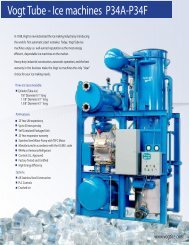
1-4INTRODUCTION<strong>P24F</strong> <strong>Service</strong> <strong>Manual</strong>FIGURE 1-1<strong>P24F</strong> Front Side (Control Panel)10/18/07
<strong>P24F</strong> <strong>Service</strong> <strong>Manual</strong>1-5INTRODUCTIONFIGURE 1-2<strong>P24F</strong> Right Side10/18/07
1-6INTRODUCTION<strong>P24F</strong> <strong>Service</strong> <strong>Manual</strong>FIGURE 1-3<strong>P24F</strong> Back Side10/18/07
<strong>P24F</strong> <strong>Service</strong> <strong>Manual</strong>1-7INTRODUCTIONFIGURE 1-4<strong>P24F</strong> Left Side10/18/07
<strong>P24F</strong> <strong>Service</strong> <strong>Manual</strong>2-1RECEIPT OF YOUR TUBE-ICE MACHINE2. Receipt Of Your <strong>Tube</strong>-<strong>Ice</strong> Machine! CAUTION !Only service personnel experienced in refrigeration systems andqualified to work on high amperage electrical equipment shouldbe allowed to install or service this <strong>Tube</strong>-<strong>Ice</strong> ® machine.Eye protection should be worn by all personnelworking on or around the <strong>Tube</strong>-<strong>Ice</strong> ® machine.It is very important that you are familiar with and adhere toall local, state, and federal, etc. ordinances and laws regardingthe handling, storing, and use of R-22 or R-404a refrigerant.An approved refrigerant mask should be readily availablefor use in an emergency and all personnel should be awareof its location and proper use.! CAUTION !Inspection. As soon as you receive your machine, inspect it for any damage. If damage issuspected, note it on the shipper’s papers (i.e., the trucker’s Bill of Lading). Immediately make aseparate written request for inspection by the freight line’s agent. Any repair work or alteration tothe machine without the permission of <strong>Tube</strong>-<strong>Ice</strong> LLC can void the machine’s warranty. You shouldalso notify your <strong>Vogt</strong> distributor or the factory.Description Of Machine. A <strong>Vogt</strong> package <strong>Tube</strong>-<strong>Ice</strong> ® machine is a complete ice producing plantrequiring only make-up water supply, condenser water supply, electrical connection, and the properrefrigerant charge.The machine has been fully factory tested prior to shipment and should require minimumadjustment.The compressor oil is drained and the compressor suction strainer is cleaned and the cloth filter isremoved. The crankcase is inspected and cleaned by removing the side handhole cover, swabbingout the remaining oil and wiping the interior sides and bottom with a clean dry cloth. New oil isadded, and the compressor is evacuated then pressurized to 20-25 psig with refrigerant.Refer to your compressor manual for additional operation, service, maintenance instructions, andinformation.Safety Tags and Labels. Be sure to read and adhere to all special tags and labels attached to valvesor applied to various areas of the machine. They provide important information necessary for safeand efficient operation of your equipment.10/18/07
2-2RECEIPT OF YOUR TUBE-ICE MACHINE<strong>P24F</strong> <strong>Service</strong> <strong>Manual</strong>The machine is available in three different tube sizes for producing ice 7/8” OD x 1” long, 1 1/8”OD x 1” long, or 1 3/8” OD x 1” long (1” long ice is standard length). The ice is cut to length by arotating breaker type cutter. <strong>Ice</strong> can be produced up to 1 1/2” long by modifying the spacers underthe adapter plates (see Chapter 10, “<strong>Ice</strong> Length” for modifying instructions). Crushed ice is alsoavailable by modifying the cutter and making minor adjustments to the machine (see Chapter 10,“Crushed <strong>Ice</strong>”).25T A L F B 5 46 NC 000Nominal Capacity(“T”= tons/day)“25T” – 25 tons/day“50T” – 50 tons/day“80T” – 80 tons/dayModel VariationA letter assigned to indicatemajor variations within any onefamily seriesBasic Configuration“P” – Package“L” - LowsideRefrigerant“F” – R-22“A” – Ammonia“H” – R-404aType of <strong>Ice</strong>“B” – Cylinder“K” – Crushed“L” – 1 ½” Long <strong>Ice</strong>Product Variation CodeA number or letter designatorassigned to specific variationswithin a family series“000 or Blank” – StandardProductConsult factory for specificcode interpretationCondenser Type“WC” – Water Cooled“NC” – No CondenserElectrical Codes“26” – 208/230-3-60“46” – 460-3-60“25” – 200-3-50“45” – 400-3-50<strong>Tube</strong> Size(In ¼’s of an inch)“4” – 1”“5” – 1 ¼”“6” – 1 ½”“7” – 1 ¾”“8” – 2”FIGURE 2-1Model Designation for P-Series <strong>Ice</strong> Machines10/18/07
<strong>P24F</strong> <strong>Service</strong> <strong>Manual</strong>2-3RECEIPT OF YOUR TUBE-ICE MACHINERated Capacity. The <strong>Tube</strong>-<strong>Ice</strong> ® machine is rated to produce a given amount of ice when operatingunder the proper conditions as specified in this manual. You should be prepared to handle the iceproduced as it is discharged from the machine and move it to your storage or bagging area promptly.The following specifications are given to help you do just that.Model <strong>P24F</strong>-1.5” Model <strong>P24F</strong>-1.25” Model <strong>P24F</strong>-1”MakeupMakeupWater Capacity Tons/day Water Capacity Tons/dayGPM (2000 lbs/24 hrs.) GPM (2000 lbs/24 hours)MakeupWaterGPMMakeup WaterTemp.Capacity Tons/day(2000 lbs/24 hours)85°F/29°C 21.4 4.46 21.5 4.48 20.8 4.3380°F/24°C 21.9 4.57 22.6 4.71 21.7 4.5375°F/23°C 22.5 4.69 23.2 4.83 22.3 4.6470°F/21°C 23.1 4.81 23.8 4.95 22.8 4.7665°F/18°C 23.7 4.94 24.4 5.09 23.4 4.8860°F/15°C 24.3 5.07 25.1 5.23 24.0 5.0055°F/13°C 25.0 5.70 25.8 5.37 24.7 5.14<strong>Ice</strong> lb/harvest 750 lbs/340 Kg 600 lbs/272 Kg 450 lbs/204 KgShippingweight (withoutcharge)Operatingweight12,500 lbs/5443 Kg 12,700 lbs/5443 Kg 12,300 lbs/5261 Kg14,700 lbs/ 6259 Kg 14,800 lbs/ 6259 Kg 14,190 lbs/6010 KgNotes:1. Makeup water is average flow and includes 25% blowdown. Peak flow rate is 15 GPM. at 40 PSI minimum. When water quality is good,machine can be operated with 5% to 10% blowdown.2. Ratings are at 90°F ambient for ice machine.3. Capacity ratings are based on 85°F water entering condenser. For entering water temperatures above 85°F, deduct 4% in capacity for each 5°F.4. Capacity shown is the average for model. Individual machines may vary up to 5% above or below depending on field conditions.TABLE 2-1<strong>P24F</strong> SpecificationsStorage (prior to installation or start-up). The machine must not be stored or installed in an areathat is subject to reach temperatures at or above 110°F (43.3°C). Temperatures above this maycause the relief valves to open and result in the loss of refrigerant.10/18/07
2-4RECEIPT OF YOUR TUBE-ICE MACHINE<strong>P24F</strong> <strong>Service</strong> <strong>Manual</strong>10/18/07
<strong>P24F</strong> <strong>Service</strong> <strong>Manual</strong>INSTALLING YOUR TUBE-ICE MACHINE3-13. Installing Your <strong>Tube</strong>-<strong>Ice</strong> MachineYour machine will be shipped to you as one package. You will need to arrange for the handling ofthe package as soon as it arrives, see the machine specifications Table 2-1 for shipping and operatingweight. Before you remove the unit from the truck, be certain that any sign of damage, howeverslight, is noted on the carrier’s papers.Note: See “Lifting Procedure” drawing furnished with this manual, Figure 3-3.Machine Room. The machine must be located inside a suitable building and must not be subjectedto ambient temperatures below 50°F (10°C) or above 110°F (43.3°C). Heat radiation from othersources (sunlight, furnaces, condenser, etc.) and unusual air current may affect the operation of themachine and should be avoided. The electrical components of the <strong>Tube</strong>-<strong>Ice</strong> ® machine are ratedIEC. Therefore, the machine should not be located in a hazardous area or sprayed with water.The machine should be installed in an area where water will not stand, but will readily drain awayfrom the machine.Space Requirements. Refer to the space diagrams, Figures 3-1A and 3-1B, for recommendedminimum clearance around the machine for ease of servicing and observation. Pay particularattention to the additional space required. If it ever becomes necessary to mechanically clean thecondenser tubes, extra space will be required on one end (preferably on the opposite end from thewater inlet and outlet) for the cleaning tools.Foundation. Refer to the foundation drawings, Figure 3-2, for recommended minimum foundationrequirements. The figures show anchor bolt details and machine anchor hole details. Contact yourlocal distributor for seismic anchoring requirements in your area.! WARNING !Lifting or moving heavy equipment should only be attempted bycompetent rigging and hoisting contractors. Never allow personnelnear or under heavy equipment when it is being moved or lifted.Failure to comply could result in personal injury or loss of life.! WARNING !Lifting Procedures. Your <strong>Tube</strong>-<strong>Ice</strong> ® machine is provided with lifting lugs for the purpose ofunloading and moving the machine to its operation location. Refer to the enclosed drawings forinstructions and illustrations of their use.<strong>P24F</strong> - Figure 3-3. Machine weight 12,500 lbs. (See TABLE 2-1)This figure are intended as a guide to unloading and lifting the <strong>P24F</strong> <strong>Tube</strong>-<strong>Ice</strong> ® machine. <strong>Tube</strong>-<strong>Ice</strong>LLC is not responsible for product damage or personnel injury or loss of life during theloading or lifting procedure.3/22/05
3-2INSTALLING YOUR TUBE-ICE MACHINE<strong>P24F</strong> <strong>Service</strong> <strong>Manual</strong>FIGURE 3-1A<strong>P24F</strong> Space Diagram (Front View)3/22/05
<strong>P24F</strong> <strong>Service</strong> <strong>Manual</strong>INSTALLING YOUR TUBE-ICE MACHINE3-3FIGURE 3-1B<strong>P24F</strong> Space Diagram (Side View)3/22/05
3-4INSTALLING YOUR TUBE-ICE MACHINE<strong>P24F</strong> <strong>Service</strong> <strong>Manual</strong>3/22/05FIGURE 3-2<strong>P24F</strong> Foundation Layout
<strong>P24F</strong> <strong>Service</strong> <strong>Manual</strong>INSTALLING YOUR TUBE-ICE MACHINE3-5FIGURE 3-3Lifting Procedure for <strong>P24F</strong>3/22/05
3-6INSTALLING YOUR TUBE-ICE MACHINE<strong>P24F</strong> <strong>Service</strong> <strong>Manual</strong>Piping and Drain Connections. See Figure 1-1 to 1-4 for connection locations.! CAUTION !Exterior shut-off valves must be provided in the waterinlet lines. The minimum inlet water pressure forsatisfactory operation of the machine is 40 psig.The maximum allowable pressure is 100 psig.! CAUTION !ModelMake-upWater InFlushingWater InCompressorCoolingWater InCompressorCoolingWater OutCondenserWaterIn and OutWaterTankDrainWaterTankOverflow<strong>P24F</strong> 3/4” FPT 3/4” FPT 3/4” FPT 1” FPT 3” FPT 2” FPT 3” FPTTABLE 3-1Water Supply and Drain ConnectionsMake-Up Water In. The water required for ice making must be potable water, safe for humanconsumption, and should be of the highest quality available. The best way to determine waterquality is to have a complete water quality analysis, by a qualified laboratory.It is advisable to install a particle filter in the make-up and flushing water lines to trap dirt, sand,rust, or other solid particles prior to entering the water tank and contaminating the ice. Be sure tosize the filter large enough to meet the water demands of 15 GPM (peak flow), allowing for arestriction through the filter as it traps these particles. The inlet water pressure should be a minimumof 40 psi. Refer to TABLE 3-1 for line size and TABLE 2-1 for average flow rate at various watertemperatures.Flushing Water In. Flushing water (blowdown) is necessary to melt ice fines and flush dissolvedsolids from the water tank during the thawing (harvest) cycle. This function is important and helpsto maintain good ice quality. If water quality is superior, installing a smaller orifice in the flushingoutlet elbow can reduce this blowdown. Make sure there is enough flushing water to prevent theaccumulation of excessive ice fines in the tank.If make-up and flushing water are from the same source, a common line to the machine can connectthem.Water Tank Drain. This valve and connection (located at the bottom of the water tank) is for thepurpose of flushing and draining the water tank of impurities, foreign material and cleaningchemicals used during servicing. It should be piped to an open drain or sump for visible discharge.It can be tied in with the overflow line but no others.Water Tank Overflow. A 3” FPT connection on the side of the water tank is provided to carryaway overflow water during the thawing (harvest cycle). This water contains ice fines accumulatedduring harvesting and dissolved solids accumulated during the freezing cycle. Do not reduce thesize of this line. Three inches is needed to provide sufficient area for ice fines to be flushed out,especially if the incoming flushing water is 55°F (13°C) or below. This overflow line should not tiein with any other drain line except the water tank drain.3/22/05
<strong>P24F</strong> <strong>Service</strong> <strong>Manual</strong>INSTALLING YOUR TUBE-ICE MACHINE3-7Condenser Water In and Out. One end of the condenser has two water connections. The lowerconnection is the inlet and the upper connection is the outlet. See TABLE 3-2 for condenser waterrequirements and machine total heat rejection. The condenser water outlet must be extended to anopen drain or sump for visible discharge.! CAUTION !The condenser water outlet must not be connected onto a pressure tight commonheader with the water tank due to the possibility that contaminated condenserwater may back up into the water tank. The condenser wateroutlet must be piped separate from the drain or sump.! CAUTION !Cooling Tower. When selecting a cooling tower, careful attention must be given to operating wetbulb conditions. It is advisable to check with your local cooling tower distributor for theirrecommendations based on actual operating conditions in your area. An average wet bulb of 78°F istypical in the U.S., but many localities have designed wet bulbs as low as 72°F or as high as 82°F.The cooling tower water pump must be capable of delivering the required volume of water throughthe condenser. Due to cooling tower location and pressure drop through water lines and regulatingvalves, the water pump must be sized for each installation. Refer to TABLE 3-2 for condenser waterrequirements. The water piping for the cooling tower and the installation of the pump must be inaccordance with the manufacturer’s instructions. Caution must be used to prevent the condenserwater pump from losing its’ prime during off cycles.Proper water treatment for the prevention of mineral and foreign matter accumulation in thecondenser or cooling tower is recommended. A water analysis should be obtained to determine theproper chemicals to use. The use of a 40-mesh strainer in the condenser water supply line is alsorecommended.Condenser water flow is based on pulldown of 30°F SST and 105°F SDT. Condenser water pressuredrop does not include water-regulating valve. Consult factory for sizing if desired.3/22/05
3-8INSTALLING YOUR TUBE-ICE MACHINE<strong>P24F</strong> <strong>Service</strong> <strong>Manual</strong><strong>P24F</strong> Condenser WaterEnteringWaterFlowGPMCond.PSID85°F 196 1580°F 131 775°F 98 470°F 78 265°F 65 260°F 56 155°F 49 150°F 44 1Total Heat RejectionTHR = 1,031,625 BTUHTABLE 3-2Condenser Water RequirementsThe following table shows the model of Marley cooling tower required for operating at various wetbulbs to cool 91°F (33°C) entering water to 85°F (29.4°C) exiting water.Cond. PDModel GPM PSIG 75°F 76°F 77°F 78°F 79°F 80°F<strong>P24F</strong> 206 18 495A 495A 495A 495A 495A 495ATABLE 3-3Marley Cooling Tower RecommendationsTower nozzles will be selected based on GPM required for condenser.The condenser water pump should be sized on GPM required for condenser at 80 ft. total dischargehead for a typical installation. However, due to cooling tower location and pressure drop throughwater lines, the water pump should be sized for each installation.The ice machine is supplied with a fan control switch for cycling the cooling tower fan on and off,thereby maintaining the proper operating head pressure. If the condenser inlet water temperature isexpected to be below 75°F/24°C, a water-regulating valve should be installed in the condenser waterinlet line and adjusted to maintain a head pressure of not less than 190 psig.See FIGURES 3-5 through 3-7 for possible cold climate installations with indoor sump.Safety Valves. Four safety pressure relief valves are an integral part of the packaged <strong>Tube</strong>-<strong>Ice</strong> ®machine. Two are located in the low side of the system on the freezer, and two are in the high sideof the system on the receiver. Vent each of the pressure relief valves to the atmosphere in such amanner as to comply with local and national codes.3/22/05
<strong>P24F</strong> <strong>Service</strong> <strong>Manual</strong>INSTALLING YOUR TUBE-ICE MACHINE3-9FIGURE 3-4Cooling Tower Piping Diagram3/22/05
3-10INSTALLING YOUR TUBE-ICE MACHINE<strong>P24F</strong> <strong>Service</strong> <strong>Manual</strong>COOLING TOWERWATERCOOLEDCONDENSERCHECK VALVEINDOOR SUMPFIGURE 3-51 PUMP/2-WAY VALVE* Poor Freeze ProtectionBecause low flow rate = high freeze chanceCOOLING TOWERWATERCOOLEDCONDENSEROnly enough water tomaintain head pressureSame flow rateto cooling towerCHECK VALVEINDOOR SUMPFIGURE 3-61 PUMP/3-WAY VALVE* Better Freeze Protection3/22/05
<strong>P24F</strong> <strong>Service</strong> <strong>Manual</strong>INSTALLING YOUR TUBE-ICE MACHINE3-11COOLING TOWERWATERCOOLEDCONDENSERCHECK VALVEINDOOR SUMPOutdoor pump is off untilindoor sump needs coolingFIGURE 3-72 PUMP/2-WAY VALVE* Best Freeze ProtectionWiring and Electrical Connections.! WARNING !Only service personnel experienced in refrigeration and qualifiedto work with high voltage electrical equipment should be allowedto install or work with the <strong>Tube</strong>-<strong>Ice</strong> ® machine.! WARNING !A fused disconnect must be provided near the <strong>Tube</strong>-<strong>Ice</strong> ® machine. The control panel andcompressor motor starter are attached to the structurals on the front of the <strong>Tube</strong>-<strong>Ice</strong> ® machine (seeFIGURE 3-8). Incoming 3 phase power will be connected at the compressor motor starter (1M).Terminals L1, L2, L3 for operation of the <strong>Tube</strong>-<strong>Ice</strong> ® machine and its controls. Rotation checking ofthe compressor, cutter motor, and water pump is required (see rotation check). Also, if one leg ofthe 3 phase power is higher or lower (“wild”), then it should be connected to terminal L2. Connectthe ground wire to the “ground” terminal provided.Make sure wires #22 and #27 are connected to the elapse time (ET) indicator in the control panel.3/22/05
3-12INSTALLING YOUR TUBE-ICE MACHINE<strong>P24F</strong> <strong>Service</strong> <strong>Manual</strong>FIGURE 3-8Power Supply ConnectionsVoltage Unbalance. Voltage unbalance can cause motors to overheat and fail. Voltage imbalancebetween any two legs should be no greater than 2%.Example: Supply voltage = 230-3-60Voltage Readings: AB = 220 VoltsBC = 225 VoltsAC = 227 VoltsAverage = (220 + 225 + 227)/3 = 224 Volts(AB) 224-220 = 4 Volts (Highest Deviation)(BC) 225-224 = 1 Volts(AC) 227-224 = 3 Volts% Voltage Unbalance = 100 x (4/224) = 1.78% “Acceptable”Important: If the supply voltage phase unbalance is more the 2%, contact your localelectric utility company.Current Unbalance. Voltage unbalance will cause a current unbalance, but a current unbalancedoes not necessarily mean that a voltage unbalance exists. A loose terminal connection or a buildupof dirt or carbon on one set of contacts would cause a higher resistance on that leg than on the othertwo legs. Current follows the path of least resistance, therefore if terminal connection L1 is loose ordirty, L2 and/or L3 will have higher current.3/22/05
<strong>P24F</strong> <strong>Service</strong> <strong>Manual</strong>INSTALLING YOUR TUBE-ICE MACHINEHigher current causes more heat to be generated in the motor windings. The maximum acceptablecurrent unbalance is 10%.3-13Example:Current Readings:L1 = 96 AmpsL2 = 91 AmpsL3 = 98 AmpsAverage = (96 + 91 + 98)/3 = 95Amps(L1) 96-95 = 1 Amps(L2) 95-91 = 4 Amps (Highest Deviation)(L3) 98-95 = 3 Amps% Current Unbalance = 100 x (4/95) = 4.2% “Acceptable”Rotation Check. The compressor, cutter, and pump motor rotation are factory synchronized, butmust be checked at installation. For cylinder ice production, the cutter disc as viewed at the icedischarge opening should turn from left to right.Check rotation by the following procedure:1. Turn the power to the machine on and check voltages.2. Make sure the water tank is full of clean water.3. Turn the Hand-Auto switch (ISS) to HAND position. The water pump will start and the freezing(1LT) and the liquid feed (2LT) pilot lights will illuminate. Check pump rotation.4. Push the MANUAL HARVEST button. The water pump will stop, the “Freezing and LiquidFeed” lights will go out, and after 20-30 seconds, the cutter motor will start. The thawing gassolenoid valve will open and the “Thawing” pilot light (3LT) will illuminate.5. Check the cutter disc rotation. It should be turning from left to right (CCW looking from thetop).6. Turn the HAND-AUTO switch to AUTO to stop the cutter.To change rotation, follow this procedure:1. Disconnect power to the machine and lock it out to make sure it can’t be turned back on.2. Check for power at L1, L2, L3 with a volt meter to make sure it is off.3. At the compressor motor starter (1M) or at the power disconnect, reverse wires L1 and L2.4. Make sure these terminals are tight and restore power to the machine.5. Perform rotation check again to confirm that it is correct.! CAUTION !Do not attempt to start the compressor motor until first making sure allconditions listed in the Installation Review Checklist and allnecessary valves have been opened for operation.! CAUTION !Auxiliary Controls or Equipment. When connecting other equipment such as tower fan,condenser pump, conveyor motors, bin level control, etc., refer to the control panel wiring drawingfor the proper connecting terminals and instructions. See Figure 6-3.3/22/05
3-14INSTALLING YOUR TUBE-ICE MACHINE<strong>P24F</strong> <strong>Service</strong> <strong>Manual</strong>! IMPORTANT !Be sure to follow the wiring schematic when incorporating overloads ofconveyor, fan, or pump motor starters (i.e., 5 MOL, 6 MOL, 7 MOL). Alsoremove jumpers as instructed. This is necessary to provide properprotection for the <strong>Tube</strong>-<strong>Ice</strong> ® machine and its component parts.! IMPORTANT !Installation Review: A Checklist. Make a visual check to be sure these steps have been takenBEFORE continuing.CHECK: _____ PRIOR TO OPENING VALVES, check all joints for leaks which may havedeveloped during shipment. (NOTE: the machine was shipped with a positive pressure of 20-25PSIG, which should be indicated on the suction and discharge gages.)CHECK: _____ All water supply and drain connections for conformity to requirements stipulated inthis manual and properly connected to inlets and outlets.CHECK: _____ Electrical supply for proper size of fuses and for compliance to local and nationalcodes. See the machine nameplate for minimum circuit ampacity and maximum fuse size.CHECK: _____ All field installed equipment (augers, conveyors, cooling towers, bin level controls,etc.) for proper installation.CHECK: _____ The applicable portion of the warranty registration/start-up report for propercompletion.CHECK: _____ Cutter gear reducer oil level oil should run out of side pipe plug when removed.CHECK: _____ The water distributors at top of freezer to make sure they are all in position (oneseated firmly in each tube with a vent tube in each distributor).! CAUTION !The crankcase heater should be energized for a minimum offour hours and the oil temperature should be 100-110°Fbefore attempting to start the compressor.! CAUTION !3/22/05
<strong>P24F</strong> <strong>Service</strong> <strong>Manual</strong>HOW YOUR TUBE-ICE MACHINE WORKS4-14. How Your <strong>Tube</strong>-<strong>Ice</strong> Machine WorksOperating Features. Your package <strong>Tube</strong>-<strong>Ice</strong> ® machine is an efficient ice producing plant. Ifinstalled and maintained properly, it will give many years of operation with a minimum amount ofrepairs. Refer to piping schematic, FIGURE 4-1 to identify component parts while following theinformation and instructions in this manual.The machine is manually started and stopped by the START and STOP push buttons. The machinewill automatically stop by safeties such as compressor, cutter and pump overloads, as well as otherauxiliary motor overloads. It will also stop automatically by high head pressure, low suctionpressure or low compressor oil pressure. The circulating water pump can be operated independentlyfor cleaning the freezer tubes and water tank by putting the HAND/AUTO selector switch in theHAND position. The machine can be manually forced into a harvest cycle with the manual harvestpush button.Principle of Operation. The freezer (2) is a shell and tube-type vessel. During the freezing period(cycle), water is constantly recirculated through the vertical tubes of the freezer by a centrifugalpump (6). Make-up water is maintained by a float valve (12) in the water tank (7). The capacitivelevel probe (65) opens and closes the liquid feed “A” solenoid valve (20A), and maintains thedesired refrigerant level in the freezer (2) (evaporator). The constant feed solenoid valve (20B)remains open during this period. Refrigerant gas from the top of the freezer (2) passes through thesuction accumulator (88), heat exchanger (13) and to the compressor (3). Here, the cool gas iscompressed to a high temperature, high-pressure gas which discharges through the oil separator (14),then through the heat coil of the condenser and then into the <strong>P24F</strong> condenser/receiver (15). In thecondenser, heat is removed and the gas is condensed to a high temperature, high-pressure liquid.The high-pressure liquid goes out the liquid line through a strainer (43), liquid “A” solenoid valves(20A & 20B) check valve (101), and hand expansion valve (17). At the hand expansion valve (17),the refrigerant expands from a saturated high-pressure liquid state to a low pressure, low temperatureliquid. This cold liquid enters the freezer (2) where it absorbs heat from the circulating water in thefreezer tubes. Cool gas is again pulled out of the freezer through the suction outlet, therebycompleting the circuit.The freezing period is completed by action of the freezer pressure switch (2PS) in the control panel.The water pump (6) stops and the “A” solenoid valve (20A) and constant feed solenoid valve (20B)closes. After a delay of 20-30 seconds, the cutter motor starts, the thawing gas “D” solenoid valve(18) opens, and the harvest (thawing) timer (2TR) is activated. Warm gas from the receiver isdischarged through the thawing chamber (16), check valve (101), and into the freezer. There itwarms the refrigerant and the outer surface of the freezer tubes, allowing the ice to release on theinside of the tubes and drop down onto the rotating cutter for sizing. After sizing, the ice drops onthe tines cutter disc and discharged through the ice discharge opening.See “Freeze Period” and “Harvest Period” for more detailed description of machine.Freeze Period. The <strong>Tube</strong>-<strong>Ice</strong> ® is frozen inside the stainless steel tubes of the freezer (2) by thedirect application of refrigerant to the outside shell side of the tubes. <strong>Ice</strong> is produced fromconstantly recirculating water down each tube. As the ice thickness increases, the freezer pressuredecreases. At a set pressure, the freezer pressure switch (2PS) energizes the relay (1CR), whichstops the water pump, closes the “A” liquid feed solenoid valves (20A & 20B), turns out the twopilot lights, refrigerant feed and freezing.10/18/07
4-2HOW YOUR TUBE-ICE MACHINE WORKS<strong>P24F</strong> <strong>Service</strong> <strong>Manual</strong>Harvest Period. About 20-30 seconds after the 1CR relay is energized, the thaw gas valve (18)opens, the “H” water flush solenoid valve (63) opens, the compressor unloads, the cutter motorstarts, the thaw timer (2TR) is energized, the red thawing gas light illuminates, and auxiliaryequipment such as conveyors etc. start. When the refrigerant in the freezer is warmed sufficiently toallow the ice in the tubes to release and be sized, the ice is discharged into the customers’ icehandling equipment. See “<strong>Ice</strong> Handling” for more information on this subject. The thaw timer(2TR) is adjustable and should be set for the time required for all the ice to clear the freezer plus 30seconds more.! CAUTION !Make sure all the ice clears the freezer with at least 30 secondsto spare before the next freezer period begins. This is to preventrefreezing and to allow the ice moving augers etc. to clear.! CAUTION !1 Control Panel 39 Water Tank Drain Valve (2”FPT)1PG Suction Pressure Gauge 41 Condenser Water Regulator2PG Discharge Pressure Gauge 41A Condenser Pressure Control2 Freezer 43 Strainer3 Compressor 44 Receiver Drain Valve4PS Dual High/Low Pressure Switch 46 Filter/ Drier5M Cutter Motor 50 Receiver Safety Valve (350 psi)5R Gear Reducer 51 Freezer Safety Valve (325 psi)6 Water Pump 52 3-Way Valve7 Water Tank (includes cutter assembly) 55 Discharge Line Stop Valve8 Water Distributing Chamber 56 Freezer/Pressure Switch (2PS)9 Water Tank Overflow (3” FPT) 58 Liquid Outlet Valve (King Valve)12 Make-Up Water Float Valve 59 Receiver Access Valve13 Heat Exchanger 61 Freezer Oil Drain Valve14 Oil Separator 62 Make-up Water Inlet Valve15 Condenser 63 Water Flush Solenoid Valve15R Receiver 65 Capacitive Level Probe16 Thawing Chamber 69 Low Suction Pressure Stop Valve17 Hand Expansion Valve 70 Oil Return Stop Valve18 Thawing Gas Solenoid Valve “D” 75 Filter /Drier Access Valve20A Liquid Feed Solenoid Valve “A” 76 Freezer Access Valve20B Constant Feed Solenoid Valve 77 Compressor Suction Access Valve23 Condenser Water Inlet (W/C Machines) 78 Compressor Discharge Access Valve24 Condenser Water Outlet (W/C Machines) 82 Discharge Pressure Gage Stop Valve28 Refrigerant Charging Valve 88 Accumulator29 Liquid Line Stop Valve 89 Thawing Gas Stop Valve30 Sight Glass 92 Receiver Liquid Return Stop Valve31 Gage Glass Stop Valve 94 Compressor Oil Pressure Safety Control (OPS)34 Compressor Suction <strong>Service</strong> Valve 101 Check Valve35 Compressor Discharge <strong>Service</strong> Valve37 Oil Charging/Drain ValvePiping Nomenclature10/18/07
<strong>P24F</strong> <strong>Service</strong> <strong>Manual</strong>HOW YOUR TUBE-ICE MACHINE WORKS4-310/18/07FIGURE 4-1Piping Schematic for <strong>P24F</strong>
4-4HOW YOUR TUBE-ICE MACHINE WORKS<strong>P24F</strong> <strong>Service</strong> <strong>Manual</strong>10/18/07
<strong>P24F</strong> <strong>Service</strong> <strong>Manual</strong>START-UP & OPERATION5-15. Start-Up & OperationRefrigeration System Review. The refrigeration system uses R-22 or R-404a refrigerant.Following the piping schematic (Figure 4-1), you will see that during the machine’s freeze cycle, thecompressor discharge gas goes through the oil separator (14) to remove any oil present in thedischarge gas and return the oil to the suction accumulator (88). From the oil separator, the dischargegas continues through a heat coil in the lower part of the condenser/receiver (15). It is thendischarged into the condenser and condensed into a liquid by the removal of heat by water passingthrough the condenser tubes. A reservoir of liquid refrigerant is accumulated in the receiver and isrequired for thawing purposes. Liquid from the receiver flows through the filter/drier (46), and theheat exchanger (13), to the liquid feed solenoid valve (20A), which opens and closes by action of thecapacitive level probe (65). The liquid is then expanded through the hand expansion valve (17) andinto the evaporator (2) (freezer). The liquid is also fed through a bypass line and the constant feedsolenoid valve (20B), which is open throughout the freeze cycle. The cold wet refrigerant that is fedthough these valves floods the evaporator and is in contact with the outside of the ice making tubeswhich water is being circulated through. The heat contained in the water passes through the wall ofthe tubes, lowering the temperature of the water and causing it to freeze and form a long tube of icethat adheres to the inside of the freezer tubes. Since the purest water freezes first, the circulatingwater continues to wash the dissolved solids down into the sump area of the water tank (7). Theflushing valve (63) helps to rid the water tank of increased dissolved solids by flushing them out theoverflow during the harvest (thawing) period.The wet suction gas leaves the freezer (2) and passes through the suction accumulator (88) and heatexchanger(13), where liquid droplets are removed, allowing the super heated dry gas to enter thesuction side of the compressor (3). The suction gas is then compressed and discharged once again,completing the cycle. As ice continues to form in the freezer tubes, the suction pressure steadilydecreases until the freezer pressure switch (not shown) is satisfied and the contact closes, initiatingthe thaw (harvest) cycle.Note: Freezing time will vary, depending on make-up water temperature and thickness of iceproduced.During the harvest period, the “D” thawing gas valve (18) opens and the compressor unloads,allowing the warm high pressure gas from the receiver to enter the freezer. As the tubes warm up toslightly above freezing, the ice inside the tubes releases and falls down onto the rotating cutter in thewater tank for sizing and discharging. Harvesting requires about three minutes, but can varydepending on ice thickness, suction pressure, and discharge pressure (thawing gas temperature).! IMPORTANT !It is a good idea and will be profitable for you to observe andbecome familiar with the proper operating characteristics of your<strong>Tube</strong>-<strong>Ice</strong> ® machine. It will help you to recognize and correct minorirregularities as they occur in order to help prevent major problems.“An ounce of prevention is worth a pound of cure.”! IMPORTANT !10/18/07
5-2START-UP & OPERATION<strong>P24F</strong> <strong>Service</strong> <strong>Manual</strong>Start-up Checklist. Be sure to complete and return the “Warranty Registration/Start-up Report”located in the front of the manual.1. See that the water-inlet connections are attached properly. The water inlet shutoff valve (62) forthe water tank should be open. The water level in the water tank should be at a height where themake-up float valve will be closed when the machine is idle and water is not running out of theoverflow (9).2. See that the condenser cooling water is connected properly and the valves are opened forcirculation.3. Fill the cooling tower sump and check the tower manufacturer’s installation and operationinstructions to make sure it is ready to run.4. Check condenser cooling water pump rotation.5. Check rotation of augers or ice handling equipment to make sure they are rotating in the properdirection.6. Check all tagged valves and make sure they are in their correct operational position (opened,closed, or automatic).7. See that the electrical disconnect is closed and the proper power is supplied to the machine.8. See that the compressor oil temperature is 100-110°F and there is no liquid refrigerant in thecrankcase. The oil level should be 1/2-3/4 of the sight glass.9. Check the elapsed time indicator (ET) and make sure wire #22 and #27 are attached.10. Reconfirm “Rotation Check” for compressor, cutter and water pump (See Section 3).Refrigerant Charge. Prior to shipping, the machine is charged with the required amount ofrefrigerant and pumped down to the condenser / receiver. All valves tagged prior to shipping mustbe opened prior to starting the machine.Total refrigerant charge required is approximately;<strong>P24F</strong> = 1200 lbs of R22 or 1058 lbs of R404a. .FIGURE 5-1.Control PanelStart-Up. Starting the machine in a freezing cycle can be accomplished as follows:10/18/07
<strong>P24F</strong> <strong>Service</strong> <strong>Manual</strong>START-UP & OPERATION5-31. Make sure the crankcase oil temperature is approximately 100°F and there is no liquidrefrigerant in the compressor crankcase.2. Turn the Hand/Auto switch (1SS) to the “Hand” position and allow the water tank to refill.MAKE SURE THE DRAIN VALVE IS CLOSED.3. Push the green “Start” push button to start the compressor and immediately observe the oilpressure, the oil level, the discharge pressure, and listen for any unusual sounds. Thecompressor starts unloaded and will load automatically after several seconds by action of thedelay timer (DT).4. Turn the Hand/Auto switch to the “Auto” position.5. When the discharge pressure increases to about 170 psi (R-22) or 205 psi (R-404a), push the“<strong>Manual</strong> Harvest” button to initiate the harvest cycle. See “Harvest Period”.6. When the suction pressure raises to 65-70 psig (R-22) or 81-85 psi (R-404a), any ice madeshould release and discharge. After all of the ice clears the cutter and auger, turn the Hand/Autoswitch to “Hand” and back to “Auto”. This will interrupt the harvest cycle and start anotherfreeze cycle. See “Freeze Cycle”.As the machine continues its freezing cycle, the liquid refrigerant will feed into the freezer until thelevel float switch (10) is satisfied. The float switch will open and close the liquid line solenoid valve(20) to maintain that level of refrigerant in the freezer during the freeze cycle. When the suctionpressure pulls down to the setting of the freezer pressure switch (2PS), the switch will close andinitiate the harvest cycle. See “Harvest Period”.Be sure to observe several complete cycles of ice production to confirm the satisfactory operation ofthe machine.! IMPORTANT !Complete the remaining part of the “Warranty/Registration Start-Up Report”and return it to <strong>Tube</strong>-<strong>Ice</strong> LLC! IMPORTANT !Check the refrigerant level at the receiver liquid gage glass to make sure it is near the operating levelmark.Adding Refrigerant. Add refrigerant while the machine is running by the following procedure:1. With a cylinder of refrigerant laying on its side, cylinder valve outlet pointing up and bottom endraised two inches higher than the valve end, connect an “approved for R-22 or R-404a” charginghose between the freezer charging valve (28) and the cylinder valve.2. Purge all air from the charging hose and open the cylinder valve gradually to check for possibleleaks around the packing nut or hose fittings. Then open the cylinder valve fully.3. While the “Refrigerant feed light” is not illuminated, open the charging valve (28) andrefrigerant will flow from the cylinder to the freezer.4. Close the cylinder valve immediately when the “refrigerant feed light” comes on and reopen itwhen the light goes out. Repeat until properly charged.As the machine is being charged, continually observe the following operating characteristics:10/18/07
5-4<strong>P24F</strong> <strong>Service</strong> <strong>Manual</strong>START-UP & OPERATIONa) Discharge pressure - 190 psi to 210 psi maximumb) Compressor oil pressure - 11-15 psi above suctionc) Liquid level in receiver - marked on gage glass guardd) Compressor oil level - approximately 1/2 glassOperating Tips.! CAUTION !Immediately close system charging valve at commencement of defrost orthawing cycle if refrigerant cylinder is connected. Never leave a refrigerantcylinder connected to system except during charging operation. Failureto observe either of these precautions can result in transferringrefrigerant from the system to the refrigerant cylinder, over-filling it,and possibly causing the cylinder to rupture because of pressurefrom expansion of the liquid refrigerant.! CAUTION !• Make sure the machine is left running in the “Auto” position. This will assure a completeshutdown if a safety or overload is tripped.• To initiate a harvest cycle, simply push the <strong>Manual</strong> Harvest push button (3PB).• To interrupt the harvest cycle and revert to a freeze cycle, turn the Hand/Auto switch to “Hand”and back to “Auto”.• Too much refrigerant in the condenser/receiver can contribute to high discharge pressure. Donot go above 13 1/2 inches from the center of the lower gage glass cock while in normaloperation. A higher level can begin to cover the condenser tubes and reduce condenserefficiency.• The circulating water overflow tubing will show that water is being slightly lifted up the tubingnear the end of the freezing cycle. If this action ceases and water begins overflowing from thetop water box, it is an indication that the tubes are freezing solid and the machine should begin aharvest cycle. It is best not to freeze the ice solid with no hole.• To cease ice production manually, allow the machine to complete the harvest period and start thefreeze period. When the “liquid feed” light comes on at the beginning of the freeze period, pushthe “Stop” button to cease ice production.10/18/07
<strong>P24F</strong> <strong>Service</strong> <strong>Manual</strong>ELECTRICAL CONTROLS6-16. Electrical ControlsYour packaged <strong>Tube</strong>-<strong>Ice</strong> ® machine is equipped with a compressor motor starter (1M) as required foryour particular voltage and a transformer (if required) for the control circuit power. The motorstarter and transformer are mounted on the machine front side (see Figures 1-1 or 1-4).The control panel wiring schematic, FIGURE 6-3, illustrates these components as well as provisionsfor auxiliary equipment which may be incorporated by the customer such as:(FU1) Main power disconnect(5M) Conveyor motor starter and overload (5MOL)(6M) Tower fan starter and overload (6MOL)(7M) Condenser pump starter and overload (7MOL)When adding motor starters for auxiliary equipment, be sure to incorporate the overload protectionas indicated between terminals #12-#13 and remove the jumper wire. This will assure that themachine will shutdown when any auxiliary equipment fails.Bin Level Control. Included in the wiring schematic is provision for a bin level control (BLC).The NC contacts of your control should be wired between terminals #8-#9 and the jumper wireremoved as indicated. Installation in this manner will allow the machine to finish the harvest periodbefore shutdown. However, the machine will still need to be manually started to resume production.Safety Switches. The machine is also equipped with the following safeties and control switches,which are mounted to the frame near the compressor. Refer to the wiring schematic FIGURE 6-3 fortheir circuitry.• High/Low dual pressure switch (1PS) to stop the machine if the compressor suction pressuregoes too low (15 psi for R-22, or 25 psi for R-404a) or the compressor discharge pressuregoes too high (300 psi for R-22, or 350 psi for R-404a). See “High/Low Pressure Switch”.• Oil failure pressure switch (0PS) to stop the machine if the compressor oil pressure drops to11 – 15 psi net (suction pressure minus oil pressure gage reading). See “Oil Pressure Switch”.9/24/07
6-2ELECTRICAL CONTROLS<strong>P24F</strong> <strong>Service</strong> <strong>Manual</strong>1M(Not shown)2M3M1CRCompressor Motor StarterPump Motor Starter(Contactor & manual motor starter)Cutter Motor Starter(Contactor & manual motor starter)Control Relay WithPneumatic TimerFIGURE 6-1Lowside Control Panel (Door Opened)Provides power to the compressor motor. Continuously energized duringfreezing and thawing with auxiliary hold contact and auxiliary contact to deenergizethe compressor crankcase heater when the motor is running.Provides power to the circulating water pump during the freezer period orwhen the Hand/Auto switch is in the “Hand” position to circulate water orice machine cleaner, etc. <strong>Manual</strong> motor starter provides motor over-currentand short circuit protection.Provides power to the cutter during the harvest period. <strong>Manual</strong> motor starterprovides motor over-current and short circuit protection.For making and breaking various circuits during freezing and thawingperiod with pneumatic timer to delay the actual thawing process. Energizedduring thawing.2CR Control Relay For making and breaking circuits during freezing and thawing. Energizedduring freezing, thawing, and hand. Momentarily de-energized at the end ofthe harvest.2TR Thawing Timer Controls the time of the harvest (thawing) period.Energized during the harvest period.DT Delay Timer Allows the compressor to start unloaded by delaying the energizing of the“UR-SOL” (unloader solenoid) valve. This gives lower in rush amps andhelps prevent belt slippage at start-up.2PS Freezer Pressure Switch Controls the desired ice thickness (hole size) by sensing the freezer suctionpressure and initiating the harvest period.ET Elapsed Time Indicator Indicates total hours of machine operation. Is powered when thecompressor is running.CB4 Circuit Breaker Overload and short circuit protection for crankcase heater and the controlcircuit.TB Terminal Block Numbered for multiple wire connections and ease of troubleshooting.DS2(not shown)CE panel-Lowside DisconnectUsed to disconnect power from panel when panel door opened.TABLE 6-1Description of Control Panel Parts (Inside)9/24/07
<strong>P24F</strong> <strong>Service</strong> <strong>Manual</strong>ELECTRICAL CONTROLS6-3FIGURE 6-2Lowside Control Panel (Hinged Door)1LT Amber Pilot Light - Freezing Illuminated during the freeze period or whenever the circulating waterpump is running.2LT Clear Pilot Light - Liquid Feed Illuminated when the circulating water pump is running and the floatswitch (10) is closed. Indicates that the liquid line solenoid valve(20A) is opened.3LT Red Pilot Light - Thawing Illuminated when the machine is in a harvest period.2PB Green Push Button - Start For starting the compressor motor and ice production. (NO)1PB Red Push Button - Stop For stopping the compressor motor and ice production. (NC)3PB White Push Button - <strong>Manual</strong> Harvest For manually initiating a harvest cycle. (NO)1SS Selector Switch - Hand/Auto “Hand” position for running the circulating water pump independentlyat start-up or for cleaning the freezer tubes and water tank.“Auto” position for provision of automatic system shutdown if there isa control circuit power interruption.TABLE 6-2Description of Control Panel Parts (Outer Door)9/24/07
6-4ELECTRICAL CONTROLS<strong>P24F</strong> <strong>Service</strong> <strong>Manual</strong>DS2FIGURE 6-3Electrical Schematic for <strong>P24F</strong> all Voltages, 50-60 Hz.9/24/07
<strong>P24F</strong> <strong>Service</strong> <strong>Manual</strong>ELECTRICAL CONTROLS6-5FIGURE 6-4Level Column Wiring for <strong>P24F</strong> all Voltages, 50-60 Hz.9/24/07
6-6ELECTRICAL CONTROLS<strong>P24F</strong> <strong>Service</strong> <strong>Manual</strong>FIGURE 6-5Part Wind Start Compressor Motor Starter1M1 Motor Starter contactor #1 Used to start compressor motor. Energizes first.1M1OL Overload Relay #1 Provide over-current protection for one half of motor1M2 Motor Starter contactor #1 Used to start compressor motor. Is energized approximately 1 second after1M1 is energized.1M2OL Overload Relay #1 Provides over-current protection for one half of motorCB1 Circuit Breaker – 3 pole Provides short circuit protection and a disconnecting means to lowsidecontrol panel. Supplies power to lowside unit.FB1 Fuse Block #1 Provides short circuit protection for one half of motor (3 fuses)FB2 Fuse Block #2 Provides short circuit protection for one half of motor (3 fuses)R1 Relay Relay used to energize 1M2 contactor.Note: R1 is a control relay used on machines where contactor 1M2 is toolarge for TR to energize.TB1 Terminal Block #1 Main Power connection.TB2 Terminal Block #2 Secondary terminal block. Connections to Lowside panel.TR Delay Timer Used to delay second motor starter (1M2). Timer either connected to R1or 1M2 coil connection.DS1(not shown)CE panel - HighsideDisconnectUsed to disconnect power from panel when panel door opened.TABLE 6-3Description of Control Panel Parts9/24/07
<strong>P24F</strong> <strong>Service</strong> <strong>Manual</strong>ELECTRICAL CONTROLS6-7FIGURE 6-6Across the Line Compressor Motor Starter1M Motor Starter contactor Used to start compressor motor.1MOL Overload Relay Provide over-current protection for compressor motor.CB1 Circuit Breaker – 3 pole Provides short circuit protection and a disconnecting means to lowsidecontrol panel. Supplies power to lowside unit.TB Terminal Block Used for connections to Lowside panel.DS1(not shown)CE panel - Highside DisconnectUsed to disconnect power from panel when panel door opened.TABLE 6-4Description of Control Panel Parts9/24/07
6-8ELECTRICAL CONTROLS<strong>P24F</strong> <strong>Service</strong> <strong>Manual</strong>9/24/07
<strong>P24F</strong> <strong>Service</strong> <strong>Manual</strong> 7-1MAINTENANCE7. MaintenancePreventative Maintenance. A careful inspection of the <strong>Tube</strong>-<strong>Ice</strong> ® machine for leaks and correctoperational functions at the time of installation and start-up will begin its long satisfactory life ofservice. In order to insure this degree of dependability, a systematic maintenance program isnecessary. Therefore, the following schedule is suggested as a minimum.A. Daily1) Check operating pressures (suction, discharge, oil).2) Check ice quality.3) Check “ice out” time (maintain 30 seconds of continued harvest after last ice is out).4) Check compressor oil level.5) Check refrigerant operation level.6) Check frost pattern on freezer shell and suction line.7) Check make-up water float valve adjustment.B. Weekly (in addition to daily checks)1) Check all belts for proper tension. Do not use belt dressings.2) Check for leaks after 400 hours or four weeks of operationC. Monthly (in addition to weekly checks)1) Check calibration and operation of all controls (high and low pressure switches, oil pressureswitch, etc.)2) Check cooling tower spray nozzles and pump suction screen for scaling and algae (consultwater treatment suppliers for corrective measures).3) Check water distributors in freezer for scale accumulation.4) Check water tank for solids to be removed.5) Check all motor drive units (compressor, cutter and pump motors, cooling tower fan, andpump, etc) for abnormal noise and/or vibrations.6) Check oil level in gear reducer.7) Check one complete freeze/thaw cycle, record data and compare with production check ofRegistration/Start-up Report.D. Yearly (in addition to weekly and monthly)1) Check entire system for leaks.2) Drain water from condenser and cooling tower and check condenser tubes. Check closelyfor damage by corrosion or scale.3) Remove all rust from all equipment, clean, and paint.4) Check all motors for shaft wear and end play.5) Check operation and general condition of all electrical controls, relays, motor starters, andsolenoid valves.6) Check freezing time, ice release time, and ice out time.7) Change oil in gear reducer box once a year.8) Lubricate compressor motor bearings.9) Drain compressor oil, open compressor, inspect and clean inside crankcase. Change oilfilter and add new oil. Inspect compressor suction strainer.1/11/2006
7-2 <strong>P24F</strong> <strong>Service</strong> <strong>Manual</strong>MAINTENANCEPREVENTATIVE MAINTENANCE FORMThis form can be removed and duplicated for record keeping.Date: _____________ Model #: ________________________ Serial #: _____________The following service performed and checked:Hour meter reading _______________ , Ambient temperature (inside)_______ °FMake-Up water float valve adjusted properlyWater distributors clean and in placeAll drains freely drainingCleaned and flushed water tankCompressor oil changedCleaned and inspected inside compressor crankcaseChanged compressor oil filterChecked/adjusted compressor belt tensionLubricate compressor motor bearingsCheck/change cutter gear reducer oilCheck/adjust cutter drive gear meshingLeak check entire systemCheck liquid refrigerant level in receiverCompressor crankcase heater workingCompressor net oil pressure (gage reading less suction)Motor amps: Compressor ________ Cutter ________ Pump ________Suction psig (end of freeze) __________ Discharge psig (end of freeze)_____________Suction psig (end of thaw) __________ Discharge psig (end of thaw) _____________Compressor water out ____°F Tower fan cycles ___ On ___ OffProduction CheckTestCycle#1#2#3#4Make-upWaterTempFreezingTimeMin/SecHarvestTimeMin/SecFirst<strong>Ice</strong> OutMin/SecAll<strong>Ice</strong> OutMin/SecAvg.HoleSize<strong>Ice</strong> lb.Per Harvest(est)<strong>Ice</strong> lb.Per Day(est)Comments: _________________________________________________________________________________________________________________________________________________________________________________________________________________________________________Name: __________________________________1/11/2006
<strong>P24F</strong> <strong>Service</strong> <strong>Manual</strong> 7-3MAINTENANCE<strong>Ice</strong> Making Section. The ice making section of the <strong>Tube</strong>-<strong>Ice</strong> ® machine should be cleaned at leasttwice a year (more often if water conditions cause mineral build up). Use an approved food-gradeice machine cleaner. The water pump is used to circulate the cleaner through the system. Forcomplete instructions, follow the “Cleaning Procedure” below.Cleaning Procedure.1. Stop the machine at the end of harvest.2. Shut off make-up water supply.3. Drain the water tank, flushing out any loose sediment.4. Close the drain valve and fill the tank with warm water. Warm water promotes faster cleaning.5. Cover the ice discharge opening to prevent contaminating any stored ice by splashing water out.6. Add sufficient ice machine cleaner to the water tank.P24 tank = 2.5 gallons water per inch of water height in tank, 13” = 32.5 gallonsMix cleaning solution according to manufacturer’s recommendations.7. Remove top water box cover, inspect distributors, remove any hard particles from orifices, andmake sure all distributors are in place. Replace cover.8. Turn Hand/Auto switch to “Hand” position and circulate the cleaning solution until deposits aredissolved or the solution is neutralized. After draining, the pump may have to be stopped andrestarted to dispel air.9. Turn switch to “Auto” position to stop the pump. Drain and flush the water tank. Repeatcleaning as necessary.10. After cleaning, fill the tank with fresh water, start the pump again, and circulate for 15 minutes.11. Stop the pump, drain and flush the tank and again refill with fresh water.12. Remove the cover from the ice discharge opening, and clean any area that may have beensplashed with solution during cleaning.13. Make sure the make-up water float valve is adjusted properly and the drain valve is closed.14. Start and stop the pump again to make sure it is circulating water and it is not air bound.You are now ready to produce ice.Water Distributors. The water distributors are located under the top freezer cover. Thesedistributors are similar in design to those used in mid-size and small machines (i.e. P18F, P118, etc.)except they have a small vent tube. It is important that this plastic vent tube remain in place in eachdistributor. The distributors may require occasional or periodic cleaning to remove solids, foreignparticles, or mineral deposit accumulated from the circulating make-up (ice making) water. Thefrequency of cleaning operation will depend on the characteristics of the water supply. Thedistributors need inspection when the inside diameter of a large portion of the ice becomes irregular(due to channeling of water), if some of the ice is opaque or if there is a noticeable decrease in icecapacity and quality.<strong>Tube</strong> Size 1 1/2” 1 1/4” 1”Number of Distributors 144 198 264TABLE 7-1Water DistributorsYou may look through the plastic freezer cover to inspect the water distributors if the view is clear.For a closer inspection you should stop the unit, remove the nuts and retaining ring sections and liftoff the top cover. Make sure the two orifices in the side of each distributor are open, the vent tubesare in place, and a distributor and vent tube assembly is installed firmly in each tube.1/11/2006
7-4 <strong>P24F</strong> <strong>Service</strong> <strong>Manual</strong>MAINTENANCE1/11/2006To remove the water distributors for cleaning:1. Grip the top of the distributor body (not at the vent tube) with adjustable pliers.2. Hold and twist the distributor while pulling upward.3. Lift the distributor out of the hole.To install the distributors:1. Insert one in each tube hole and seat firmly by using a short piece of pipe or conduit.2. Slide the pipe or conduit down over the vent tube and gently tap the distributor in place.3. Do not allow the distributor to be recessed below the top of the tube sheet.To replace the cover:1. Replace water distributor box cover gasket.2. Install the cover over the bolt studs.3. Install the four (4) cover retaining rings sections and nuts.4. Tighten the wing nuts firmly to prevent foreign materials from entering the water box.Note: The freezer cover and gasket are not intended to hold the pressure of the circulating waterin the event of a freeze up. Therefore every effort should be made to prevent the <strong>Tube</strong>-<strong>Ice</strong> ® fromfreezing solid (with no hole).<strong>Tube</strong> Size 1 1/2” 1 1/4” 1”Hole Size 1/4”-3/8” Avg. 1/8”-3/16” Avg. 1/16”-1/8” Avg.TABLE 7-2Average Hole Size In <strong>Tube</strong>-<strong>Ice</strong> ®Water Tank. The production of opaque ice can indicate that the water in the water tank contains aconcentrated amount of solids or salts. See Troubleshooting, “Poor <strong>Ice</strong> Quality”.To clean the water tank:1. Stop the machine at the end of harvest.2. Shut off the make-up water supply.3. Open the drain valve and drain the tank.4. Remove the water box cover and flush out any loose sediment from the tank. The wire meshscreen can be removed if necessary.5. If further cleaning is needed, follow “Cleaning Procedure”.6. If further cleaning is not needed, close the drain valve and refill the tank with fresh water.7. Make sure the float valve is adjusted properly and install the water box cover.8. Start and stop the pump again to make sure it is circulating water and is not air bound.Water Cooled Condenser Cleaning. As water evaporates from a cooling tower, the solidimpurities remain and must be flushed from the system to prevent a scale build-up in the condenserand cooling tower. This can be accomplished by a continuous bleed off valve located in the pumpdischarge line. The valve should be adjusted to bleed off an equal amount of water that isevaporated. If water hardness is very high, a higher bleed off rate or chemical treatment may berequired. Consult you local water treatment company for recommendations.If after a period of time, scale has formed inside the tubes, mechanical cleaning may be necessary.See “Servicing Section--Condenser”.
<strong>P24F</strong> <strong>Service</strong> <strong>Manual</strong> 7-5MAINTENANCECooling Tower/Evap Condenser. See Figure 3-4 for parts location.1. Bleed off valve. The bleed off valve should be checked monthly to assure that it is not blockedand that water is flowing as required. If the unit is controlled by a water treatment system, thebleed off valve may not be required.2. Strainer. The pan or sump strainer is located in the bottom of the sump at the suction connectionto the pump. The strainer should be inspected monthly and kept clean. Do not operate the unitwithout the strainer in place.3. Make-up water float valve. This valve should be checked monthly for proper operation andadjustment. It should be adjusted to maintain a water level below the overflow and high enoughto prevent the pump from cavitating when the system is in operation.4. Spray nozzles. The spray nozzles should be checked monthly to make sure none are restrictedand the spray pattern is complete and even.5. Pump motor and fan motor. The motors should be checked and/or lubricated every six monthsaccording to the motor manufacturer’s recommendations.6. Fan bearings. The fan bearings should be lubricated every six months. Make sure the propergrade of grease is used (normally conforms to NLCI-Grade 2). It is best to use a hand greasegun.7. Fan belts. The fan belt tension should be checked weekly for the first two weeks of operation,then monthly during continuous use.The best tension for a V-belt is the lowest tension at which the belt will not slip under its full load.Never use dressing on V-belts. Keep belts and grooves clean and free of oil, grease, and foreignmaterial. Clean with non-flammable, non-toxic degreasing agent or commercial detergent andwater.! CAUTION !Follow all lock-out and tag-out procedures before servicing any electrical equipment.! CAUTION !<strong>Service</strong>/Frequency Start-Up Monthly Six Months ShutdownClean debris from unit X X XClean strainer and flush sump X X XCheck fan and pump rotationXClean spray nozzles X XCheck belt tension X XCheck for noise/vibration X XCheck/adjust make-up water valve X XCheck/adjust bleed rate X XCheck/lubricate fan bearings X XLubricate motor base adj. screw X X XDrain sump and pipingXTABLE 7-3Cooling Tower Maintenance Schedule1/11/2006Compressor. In starting and charging the unit, the oil sight glass should be continually checked tomake sure an adequate oil level is maintained. The oil level should be 1/4-3/4 of the sight glass. If
7-6 <strong>P24F</strong> <strong>Service</strong> <strong>Manual</strong>MAINTENANCEthe oil level drops below 1/4 of the glass, add refrigeration oil (Texaco WF32 or equivalent for R-22,Mobil EAL Arctic 22CC POE or equivalent for R-404a) as per the compressor manufacturerrecommendations. Never allow the oil level to be out of sight, above or below the sight glass whenthe compressor is operating. The compressor contains approximately 5 gallons (22.7 liters) ofrefrigeration oil.! CAUTION !The crankcase heater should be energized for a minimum offour hours and the oil temperature should be 100°-110°Fbefore attempting to start the compressor.! CAUTION !During operation, the specified net oil pressure should be maintained for proper lubrication andoperation of the cylinder unloader mechanism.Net oil pressure: 45-55 psigNote: Net oil pressure is calculated by subtracting the compressor suction pressure from the oilpressure gage reading while the compressor is running.Example: Oil pressure gage reading: 65 psigSuction pressure gage reading: 40 psigNet Oil Pressure: 25 psigThe compressor oil should be changed at close intervals during initial break-in operation and up tothe first 1000 hours (see Table 7-4). Your machine was test operated at the factory and compressoroil was drained, crankcase cleaned, suction strainer sock cleaned, new oil filter installed (ifapplicable), and clean oil added prior to shipping.Note: It is the owner’s responsibility to make sure normal maintenance is initiated to insure that thecompressor is not subjected to premature wear or failure due to neglect or lack of sufficientmaintenance and care.Frequency1st 2nd 3rd 4th ThereafterChange oil and Filter 50 hr. 500 hr. 1500 hr. 4000 hr. every 4000 hrs.Clean suction strainer cloth 200 hr. 500 hr. Remove if clogging is minimalTABLE 7-4Compressor MaintenanceThe above maintenance is only a guide. The compressor should be inspected anytime there isunusual noise, damage is suspected or the oil becomes discolored. The oil should be changed anytime the compressor is opened. For specific recommendations and instructions, refer to theparticular compressor manufacturer’s manual. See “Compressor Oil Changing and Inspection”1/11/2006Cutter Gear Reducer. The oil level of the gear reducer should be checked monthly or when thereis any evidence of leakage. The correct oil level is indicated by the pipe plug in the side of the gear
<strong>P24F</strong> <strong>Service</strong> <strong>Manual</strong> 7-7MAINTENANCEhousing. The oil should run out of the hole when the plug is taken out. If low, add oil through oneof the top plugged holes. A high grade lubricant such as Mobil 600W or SAE 140 gear oil should beused. The oil should be changed annually. Drain the oil and flush the gear case with mineral spirits.Drain the mineral spirits completely and refill with the proper oil.Note: If a USDA high food grade lubricant is desired, use Chevron FM Lubricating Oil 460X.! CAUTION !Follow all lock-out and tag-out procedures before servicing any electrical equipment.! CAUTION !V-Belt Maintenance. Belts should be kept clean, free of oil and protected from sunlight as much aspossible. To clean belts, wipe with a dry cloth. The safest way to remove dirt and grime is to washthe belt with soap and water and rinse well. BELT DRESSING SHOULD NEVER BE USED ONA V-BELT DRIVE.The tension on a 5 rib, banded V-belt can be checked as follows:1. Apply 50-75 pounds of deflection force uniformly across the belt, midway between the pulleycenters. Lay a straight edge across the sheaves to measure the deflection. The deflection shouldbe 5/8” to 3/4”.2. When installing a new belt, move the sheaves together to allow the belt to slide across thesheaves. Rotate the belt and sheaves to obtain proper seating. Remove the slack from the beltand measure the outside circumference to the nearest 1/4”. Multiply this reading by .0075 and.001, add these amounts to the circumference reading. Elongate the belt to the new length.Example: 105 x .0075 = .7875, 105+ .7875 = 105.7875=105 3/4” min.105 x .001 = 1.05, 105+ 1.05 = 106.05=106 1/16” max.3. Check Compressor sheave and motor sheave with a straight edge to be sure they are parallel andin the same plane.4. The tension should be checked after 24 to 48 hours of operation to compensate for initial stretchand wear-in. Periodic checks should be made and tension restored as necessary.General Rules:1. The best tension for a V-belt drive is the lowest tension at which the belt will not slip under thehighest load. Too much tension shortens belt and bearing life.2. Check tension often during the first 48 hours of operation and periodically afterwards.3. Keep belts and sheaves free of any foreign material which may cause slippage.4. If a belt slips, tighten it.1/11/2006
7-8 <strong>P24F</strong> <strong>Service</strong> <strong>Manual</strong>MAINTENANCE1/11/2006
<strong>P24F</strong> <strong>Service</strong> <strong>Manual</strong>TROUBLESHOOTING8-18. TroubleshootingNote: Your machine’s electrical system has several built-in safety and overload protection featuresto stop operation when a single component fails, or there is a problem from an outside sourcesuch a power supply. Make sure all auxiliary equipment is connected to incorporate safetyand overload circuits and protect all related equipment.When the machine stops, it must be manually restarted by pushing the “Start” button. If it stoppedwhile in a freeze cycle, it should be manually harvested to remove all ice from the freezer. This isdone by pushing the white “<strong>Manual</strong> Harvest” button.Always check the machine operation thoroughly after remedying the problem. Be sure to correct thesource or cause of the problem to prevent the problem from occurring again.SymptomPageMachine stopped 8-2Freeze-up due to extended freeze period 8-4Freeze-up due to ice failing to discharge 8-5Low ice capacity 8-6Poor ice quality 8-7High discharge pressure 8-8Low discharge pressure 8-9High suction pressure 8-9Compressor running unloaded during freeze 8-9Compressor oil pressure low 8-10Compressor loosing oil excessively 8-10Machine short cycles 8-11Shut down by oil pressure switch 8-11High compressor discharge temperature 8-11Suction line frosting to compressor 8-12Notice:Opening the compressor for observation or determination of failure does NOT void thewarranty.Contact your distributor first for technical service assistance about operation problems not coveredin this manual.1/11/06
8-2TROUBLESHOOTING<strong>P24F</strong> <strong>Service</strong> <strong>Manual</strong>Symptom: Machine StoppedPossible CausePower failure or interruptionCircuit breaker (CB4) for control circuittrippedCompressor motor starter overload (1MOL)trippedWater pump, cutter motor, tower fan, towerpump, conveyor motor, overload trippedFreezer water pump motor overload (2MOL)trippedCutter motor overload (3MOL) trippedBin level control (optional) openPossible RemedyCheck fused disconnect or circuit breakersupplying power to the machine. If power hasbeen off, make sure the crankcase heater isenergized and there is no liquid refrigerant inthe compressor crankcase prior to restarting thecompressor. If ice is in the freezer, initiate amanual harvest.Check compressor crankcase heater, coils ofrelays, contactors, starters, solenoid valves, andthawing timer for a ground. Repair or replaceany defective part and reset circuit breaker.Make sure there is no liquid refrigerant in thecompressor crankcase prior to restarting themachine.Check for a loose connection on all motorstarter and motor terminals which could causeexcessive amp draw. Reset overload andrestart the machine, check amperage, powersupply, and head pressure. (Check TR in partwind starts only).Check for loose connection on all terminalswhich could cause excessive amp draw. Resetthe overload and manually run that particularmotor to check actual voltage and amperageagainst motor rating.Check for loose terminal connections and/ordefective breaker (CB2), reset the overload andstart the pump by turning the selector switch(1SS) to “Hand”. Check voltage and amperageagainst motor rating. Confirm proper rotation.Check for loose terminal connections andblown fuse, reset the overload. Clear all icethat may have jammed cutter. Turn theselector switch (1SS) to “Hand” and push the“<strong>Manual</strong> Harvest” button. Check voltage andamps against motor rating. If tripping repeatsbut ice is not jammed, check the gear reducerfor resistance, cutter bearings for wear, drivegear and ring gear for proper engagement, andreducer motor for defect or single phasing.Adjust or replace control as required. If binlevel control is not used, make sure jumperwire #8 and #9 is installed at of the terminalblock.1/11/06
<strong>P24F</strong> <strong>Service</strong> <strong>Manual</strong>TROUBLESHOOTING8-3Symptom: Machine Stopped (con’t)Possible CauseHigh/Low pressure safety switch (1PS) trippedLow oil pressure tripped (OPS)Possible RemedyIf the machine stops by low pressure cutout,the switch will reset automatically when thepressure raises to the “cut-in” setting. Checkthaw gas valve (18) to make sure it opensduring harvest time.If the machine stops by high pressure cutout,the switch will have to be manually reset afterthe pressure drops below the “cut-in” setting.Check the head pressure during the next freezecycle. See FIGURE 9-2, Section 9 (High/LowPressure Switch).<strong>Manual</strong>ly reset the switch after the switchheater cools. Check the crankcase oil level(1/4-3/4 full). Add oil if below 1/4 glassbefore attempting to restart the machine.Restart the machine and check net oil pressure(net oil pressure = oil pump line pressureminus crankcase suction pressure). SeeFIGURE 9-4, Section 9 (Oil Pressure Switch).See “Low Compressor Oil Pressure”.Defective control panel component such as1PB, 1SS, 1M contact, 2CR contactCircuit breaker (CB2 or CB3) for pump orcutter motor trippedHigh refrigerant level in evaporator due toliquid feed valve “A1” leaking throughHigh refrigerant level in evaporator due tolevel controller failureNet oil pressure range: 45-55 psigSee FIGURE 6-3, Wiring Schematic, andcheck for open circuit. Refer to FIGURES 6-1and 6-2, Control Panel to identify parts. Checkfor loose wires. Replace defective part, restartmachine, check power supply, and currentdraw.Check for loose connection on all terminals,reset breaker and check amp draw againstbreaker rating. Check voltage and currentunbalance, Section 3. Replace breaker ifdefective.Check the manual opening stem to make sure itis in the automatic position (stem screwed out).Check for leakage by sound, temperaturedifference and frost during the freeze cycle.Leakage should stop by closing the hand stopvalve downstream of thaw gas valve. Isolateand repair or replace the valve as needed.Check liquid level control for proper operationand set-point. Replace defective part.1/11/06
8-4TROUBLESHOOTING<strong>P24F</strong> <strong>Service</strong> <strong>Manual</strong>Symptom:Freeze-up due to extended freeze periodPossible CauseFreezer pressure switch (2PS) set too low ordefectiveWater tank drain valve, make-up water floatvalve or flushing valve stuck or openedThaw gas solenoid valve (18) leaking throughduring freezeLevel control set to highCompressor running unloadedPossible RemedyAdjust switch or replace if defective. SeeFIGURE 9-1.Close, repair, or replace valve as needed. Thefloat valve should be adjusted low enough thatwater should not run out the tank overflowduring the freeze cycle.Check the manual opening stem to make sure itis in the automatic position (stem screwed in).Check for leakage by sound, temperaturedifference and frost during the freeze cycle.Leakage should stop by closing the hand stopvalve downstream of thaw gas valve. Isolateand repair or replace the valve as needed.Check liquid level control for proper operationand set-point. Replace defective part.If the compressor is running unloaded, themotor amp draw will only be 60%-70% of thenormal amp draw of a loaded compressor.Check the delay timer (DT) electrical circuit tomake sure the “UR-SOL” coil is not energized.Refer to the compressor manual for normal oilpressure needed to load the compressorcylinders and any further procedures to checkthe mechanical function of the unloadermechanism.1/11/06
<strong>P24F</strong> <strong>Service</strong> <strong>Manual</strong>TROUBLESHOOTING8-5Symptom: Freeze-up due to ice failing to dischargePossible CausePossible RemedyExtended freeze period Check freezer pressure switch (2PS)adjustment. See FIGURE 9-1 for adjustmentand TABLE 7-2 for average hole size. Makesure all water distributors are in place (one ineach tube).Thaw time too shortAdjust thaw timer (2TR) to allow all ice toclear the cutter and ice discharge opening withat least 30 seconds to spare. Replace defectivetimer.Insufficient heat for thawing due to lowcondensing pressureThe head pressure should be maintained from175-200 psi for R-22 or 210-245 psi for R-404a, usually by a water regulating valve orfan cycling switch. Check to make sure thesecontrols are working properly. Cold prevailingInsufficient heat due to non-condensables(usually air) in the systemInsufficient heat due to water in therefrigeration systemInsufficient heat due to low refrigerant chargeCutter or cutter disc does not turnCompressor not running unloaded during thawcycle.wind can also be a factor.If non-condensables are present with therefrigerant, the saturated temperature will notrelate to the pressure reading at the receiverand the refrigerant will be cooler, althoughpressure will be high. Air can be purged fromthe system by following the procedure in theSection 9, “Purging Non-Condensables”.If water is present in the refrigeration system,the ice will release, but discharge very slowly.Check the refrigerant for water content(purchased kit or freezer pump-down).Remove all water by following the procedurein Section 9, “ Removing water”.The refrigerant level in the receiver should benear the operating mark at the end of a freezingcycle to provide enough volume of warm gasfor harvesting. DO NOT OVERFILLRECEIVER.Check cutter gear reducer and drive gear forproper operation and alignment. Check forbroken gear teeth or sheared shaft key.Replace defective parts.Check compressor motor Amp draw. Duringthe thaw cycle, the compressor motor Ampdraw should be 60 - 70% of normal amp drawduring the freeze cycle. Check compressorunloader solenoid coil (UR) to make sure it isenergized and the valve opening during thethaw cycle. Check oil pressure.1/11/06
8-6TROUBLESHOOTING<strong>P24F</strong> <strong>Service</strong> <strong>Manual</strong>Symptom: Low ice capacity.Suspicions of low ice capacity should be confirmed by accurate calculations of actual ice produced.Much weight can be lost by melting and fall off through augers and other ice handling equipment.1. Time the total freeze and thaw cycle for the cycle which is to be caught and weighed.2. Catch all the ice at the ice discharge opening of the machine.3. Weight the total amount of ice caught.Lbs. ice per cycleCycle time minutes X 1440 = _____ lbs. production per 24 hoursMore than one cycle should be caught and weighed to get an accurate average.Possible CauseInadequate water for ice makingWater distributors may be stopped upFreezer pressure switch or thaw timer out ofadjustmentExcessive ice chips in the water tank, causingshort cyclingCompressor running unloaded or not pumpingfull volumeRestriction in the refrigerant liquid line or levelcontroller not operating properlyLow refrigerant charge, causing re-freezeWarm make-up water for ice makingPossible RemedyWater pressure of 40 psig minimum is requiredto assure proper water supply. Check waterpressure. Check for a restriction in the incomingline or at the make-up water float valve.Check distributors and clean orifices as needed.Check hole size in <strong>Tube</strong>-<strong>Ice</strong> (See TABLE 7-2).Crushed ice should be 3/16”-1/4” thick. Checkand adjust thawing time. Thawing should be 30seconds longer than it takes for all the ice toclear the freezer.Check incoming water temperature (45°Fminimum). Check flushing valve to make sureice chips are being melted and flowing out thetank overflow during the harvest cycle.Check compressor motor amp draw. Check forbelt slippage and tighten as needed. Check forleaking compressor suction or discharge valves.Refer to your compressor manual. See otherrelated symptoms.Check for a partially closed valve or anobstruction at the filter drier, solenoid valve, orhand expansion valve. The liquid line willnormally have frost on the downstream side of arestriction, especially as the suction pressuredecreases. Check level controller set-point.Check the receiver gage glass mark for theproper level. Check for and repair leaks. Addrefrigerant.Capacity of the machine is proportional to icemaking water temperature. Warmer water willreduce the ice making capacity. Refer to Section11, Capacity Table. Check float adjustment andwater tank drain valve.1/11/06
<strong>P24F</strong> <strong>Service</strong> <strong>Manual</strong>TROUBLESHOOTING8-7Symptom: Low ice capacity (cont.)Possible CauseExcessively high head pressureThawing gas solenoid valve (18) leakingthrough during freeze cyclePossible RemedyCheck cooling tower or evap condenser tomake sure sufficient water is provided forcooling and the equipment is operational tocool the water. Also see “Symptom High HeadPressure”.Check the manual opening stem to make sure itis in the automatic position (stem screwed in).Check for leak by sound, temperaturedifference and frost during a freeze cycle.Close the stop valve (90) to confirm suspicionof leakage. Repair or replace the valve.Symptom: Poor ice qualityPossible CauseExcessive concentration of solids in the watertank usually indicated by a build-up of mineraldeposit on the sides and bottom of the tank andopaque ice production. Also, waterdistributors restricted.Insufficient water supply indicated by a lowlevel in the tankWater pump rotation wrong directionLow refrigerant charge, causing an ice outproblem and re-freezeRestriction in liquid line, causing short freezecyclePossible RemedyPerforming a cleaning procedure as well asremoving the freezer cover and cleaning thewater distributors. Make sure the flushingvalve (63) is functioning and the tank overflowpiping is not restricted.Check water pressure, 40 psig is recommendedminimum. Check for a water line restriction,partially closed valve, or defective make-upwater float valve. Make sure the water tankdrain is closed.Check rotation in relation with arrow on pumphousing and reverse two wires at the motor ifnecessary.Check refrigerant level mark on the receiverand on the painted portion of the gage glassguard. Be sure to keep the gage glass cocksclosed when finished checking the level.Check for closed valve, defective solenoidvalve (20), level controller defective or filterdrier restricted. The liquid line will normallyhave frost on the down-stream side of arestriction, especially as the suction pressuredecreases. Check level controller set-point.1/11/06
8-8TROUBLESHOOTING<strong>P24F</strong> <strong>Service</strong> <strong>Manual</strong>Symptom: High discharge pressure (check gage accuracy)Possible CauseInsufficient water flow through the coolingtower or condenserFan control out of adjustmentNon-condensable in system.Cooling tower or evap condenser in need ofmaintenanceDirty condenser tubesToo much liquid in condenser/receivercovering tubes causing inefficiencyPossible RemedyCheck the condenser water pump to make sureit is pumping enough water as specified inTABLE 3-2. Check sump strainer screen andclean. Check condenser pump direction ofrotation.Check adjustment. Refer to FIGURE 9-3, “FanControl”. Replace if defective.If non-condensables are present with therefrigerant, the saturated temperature will notrelate to the pressure reading at the receiver.The refrigerant will be cooler, although thepressure will be high.Check fan motor and fan belts for properoperation and tension. Check spray nozzles,tubes, sump, and sump screen, foraccumulation of mineral deposit and clean asrequired. Check tower blowdown andchemical treatment if applicable.Visually inspect the condenser tubes to see ifthere is any build-up of mineral deposits,which would reduce the cooling effect of thetubes and water. Clean chemically ormechanically as applicable.Remove refrigerant so all tubes will be aboveliquid refrigerant level.1/11/06
<strong>P24F</strong> <strong>Service</strong> <strong>Manual</strong>TROUBLESHOOTING8-9Symptom: Low discharge pressure (check gage accuracy)Possible CauseFan cycling switch out of adjustment ordefectiveCompressor running unloaded or not pumpingefficientlyAmbient temperature low and prevailing windsblowing through towerToo much cold water circulating throughcondenserThaw gas valve #18 leaking throughPossible RemedyCheck adjustment. Refer to FIGURE 9-3, “FanControl”. Replace if defective.Check compressor motor amp. If thecompressor is running unloaded, the amperagewill only be approximately 60% of normal ampdraw (FLA). Refer to the compressor manual.Shield tower from prevailing winds to preventexcessive cooling. Install an indoor sump.Install a water regulating valve in the waterline form the condenser and control flow byreceiver pressure.Make sure manual opening stem is in theautomatic (screwed in) position. Repair orreplace defective parts.Symptom: High suction pressure (check gage accuracy)Possible CauseCompressor running unloaded or not pumpingefficientlyThaw gas valve #18 leaking throughDefective gagePossible RemedyCheck compressor motor amp. If thecompressor is running unloaded, the amperagewill only be approximately 60% of normal ampdraw. Refer to the compressor manual.Make sure manual opening stem is in theautomatic (screwed in) position. Repair orreplace defective parts.Check pressure with accurate gage and replaceas necessary.Symptom: Compressor running unloaded during freezePossible CauseLow oil pressureUnloader solenoid valve openUnloader mechanism not working properlyPossible RemedyCheck compressor net oil pressure.Net oil pressure = oil pressure gage readingless suction pressure: 11 - 15 psiRefer to the compressor manual for “OilPressure Adjustment”.Check solenoid coil to make sure it is notenergized. If valve is stuck open, replacevalve.Refer to compressor manual for unloaderinformation.1/11/06
8-10TROUBLESHOOTING<strong>P24F</strong> <strong>Service</strong> <strong>Manual</strong>Symptom: Compressor oil pressure low (check gages)See Section 7, for compressor oil pressure requirements.Possible CausePossible RemedyOil diluted with refrigerantOil will be very foamy. Check liquid feedcontrol for overfeed problem.Oil pressure regulating valve out of adjustment Adjust valve to increase oil pressure. Turnstem in to increase, out to decrease.Compressor rotation incorrectCheck rotation direction by arrow indication.Reverse rotation, if necessary.Restriction strainer, oil filter, pick-up tube oroil passageClean strainer or restriction in passage orreplace filter.Symptom: Compressor loosing oil excessivelyPossible CauseNon-effective oil separator or floatLiquid refrigerant in crankcaseCompressor piston rings seized or brokenLeaking shaft sealPossible RemedyThe oil separator will normally return a goodportion of oil leaving the compressor, if it isworking properly. Check the oil float andreturn line to see it is not restricted.Check liquid feed to make sure it is notoverfeeding and that the solenoid valves #20Aand #20B are not leaking through when themachine is stopped.Check compressor efficiency. If rings areseized or broken, replace defective parts.A few drops per minute is okay. If refrigerantis leaking, replace the seal.1/11/06
<strong>P24F</strong> <strong>Service</strong> <strong>Manual</strong>TROUBLESHOOTING8-11Symptom: Machine short cyclesPossible CauseFreezer pressure switch (2PS) set too low ordefectiveFreeze-upClogged water distributorsLack of water for making iceLack of sufficient liquid refrigerant feedWater pump rotation incorrect or pumpdefectivePossible RemedyAdjust switch or replace if defective. SeeFIGURE 9-1.See “Freeze-up due to extended freezer period”and “Freeze-up due to ice failing to discharge”.Clean water distributors.Check water tank for sufficient water level.Checks for restriction in water line, defectivefloat valve, open drain valve, excessive icechips or low water pressure and correct.Check liquid level controller, solenoid valvesand coils #20A and #20B in liquid line,filter/drier, and refrigerant level in receiver.Check pump motor rotation. Check for leakingpump seal or defective motor and repair orreplace as needed.Symptom: Shut down by oil pressure switchPossible CauseSwitch adjusted too high or defectiveOil pressure lowLow oil levelDefective thawing timer causing long harvestcycle and oil dilutionPossible RemedyCheck switch adjustment and cutout pressureactivation against an accurate gage. Replaceswitch if defective. See Figure 9-4.See “Compressor oil pressure low”.Add oil.Replace defective timer.Symptom: High compressor discharge temperaturePossible CauseHigh head pressureDefective suction or discharge valvesRestriction in the discharge gas lineInternal relief valve leakingPossible RemedyCheck gage accuracy and “High dischargepressure”.Feel the compressor heads for hot spots or onehead running hot. Replace worn or leakingvalves.Check all hand and check valves to make surethey are fully opened and not stuck. Repair orreplace as needed.Check the compressor manual to see if yourcompressor is so equipped. Replaceaccordingly.1/11/06
8-12TROUBLESHOOTING<strong>P24F</strong> <strong>Service</strong> <strong>Manual</strong>Symptom: Suction line frosting to compressorPossible CauseLiquid refrigerant overfeedRefrigerant contaminated with waterPossible RemedyCheck liquid level controller to make sure it isfunctioning properly. Replace if defective.Check solenoid valves #20A and #20B to makesure they are not leaking through. Repair orreplace if defective.Test refrigerant or oil for water contamination.Completely pump the freezer out (pumpdown)and pull vacuum on freezer. Refer to <strong>Service</strong>,Section 9 “Removing Water”.1/11/06
<strong>P24F</strong> <strong>Service</strong> <strong>Manual</strong>SERVICING OPERATIONS9-1Automatic Blowdown (harvest cycle)9. Servicing OperationsA feature of this machine is a solenoid activated flushing valve (63), which is provided to eliminateor reduce the necessity for frequent flushing or cleaning of the water tank. This flushing during theharvest cycle helps to remove salts or solids accumulated in the water as a result of the freezingaction. It also helps melt ice chips that fall into the water tank during harvest. The flushing valve isopened (energized) during each thaw cycle when the water pump stops and the water in the freezertubes returns to the water tank. If water quality is superior, the blowdown can be reduced byinstalling a smaller reducer bushing in the outlet elbow.The flushing action carries accumulated salts, solids, and ice chips (fines) out through the water tankoverflow pipe. This overflow should be kept open at all times to allow the water to drain freely andkeep the water level below the cutter disc and ice discharge opening. If the flushing solenoid valveleaks through during the freeze cycle, it can be disassembled and cleaned, then reassembled.Cleaning <strong>Ice</strong> Making SectionRefer to Section 7, Maintenance for instructions for cleaning the circulating water tubes, waterdistributors, and water tank.Float valve (make-up water)The make-up water float valve (12) maintains the proper pumping level in the water tank for icemaking. The valve should be set to maintain a water level in the water tank during the freezingperiod, so that there will be a quantity of blowdown only during the thaw mode. The water levelduring the freeze cycle should always be below the overflow piping to prevent excessive waste ofcold water, resulting in loss of ice capacity.If it should become necessary to clean the float valve, close the stop valve in the make-up water lineto the machine and remove the float valve. After the valve has been cleaned and reinstalled, check toascertain if the proper water level is being maintained. After the machine is stopped and the water inthe tank seeks its normal level, there should be no water flow through the float valve or out theoverflow.It is advisable to install a large area strainer in the water supply line to protect the float valve fromdirt or solids in the water that would necessitate frequent cleaning. A strainer of 40 mesh screen isusually satisfactory.Capacitive Level ControlThe control unit houses the "brains" of the Vari-Level®, its digital readout, knobs for adjusting setpoints and differentials, and the relays themselves. Because the signal from the probe is unique, itrequires the control unit to interpret and convert it to an understandable signal and display.The control unit, which has a watertight enclosure, is mounted in an accessible area away from themovement of material and equipment. CAUTION: Do not install conduit connections into top ofcontrol unit; water can condense in conduit and drip down on control unit electronics, causingfailure.11/15/12
9-2SERVICING OPERATIONS<strong>P24F</strong> <strong>Service</strong> <strong>Manual</strong>See Section 6 of this manual for control unit electrical wiring diagram. Before connecting electricalpower, check the voltage on the control unit nameplate and the power supply at the wire leads to besure that they are the same. Supply voltage must be within +10% or –15% of listed voltage.Connect power supply leads to the quick disconnect plug (Terminals 1 & 2) and secure into theappropriate marked socket.The probe is the device that actually measures the liquid level. It accomplishes this by sending asmall, specialized signal out into the refrigerant liquid and vapor. This signal returns via the levelcolumn back to electronics inside probe housing. The strength of the returning signal is measured todetermine level. This information is continuously sent to the control unit through the control cable.When installing the probe, match its serial number with the control unit. Remove the probe from thepacking crate, being careful not to bend or whip the probe. Use nonelectrically isolating pipe threadsealant (do not use Teflon® tape) on the ¾" MPT fitting on the probe and insert in top of the levelcolumn. Tighten probe on hex; do not grip probe housing flats or electrical box. Pressure test forleaks.Probes are supplied from the factory with 50 feet of shielded control cable. If the control unit islocated less than 50 feet from probe, trim the control unit end of the cable as necessary. Securelyplace the control cable quick disconnect plug into the appropriate marked socket inside the controlunit.Setpoint and Operation. The level set point adjustment control is a slide knob with a scale inpercentage of active probe length. The percentage relates to the liquid level in the column betweenthe 3% level point and the 100% level point, as measured from the probe bottom end.The level set point has a level differential adjustment control which is a rotating knob scaled inpercentage of active probe length from 2% to 20%. These percentages relate to the number ofpercentage points above or below the set point at which the particular relay position will change, asdetailed in the next three paragraphs.LOW LEVEL ADJUSTMENT—Not used on the <strong>P24F</strong>.CONTROL LEVEL ADJUSTMENTThis set point is intended to maintain the level inside the vessel via a liquid refrigerant supplysolenoid valve, “A1”. The control level set point is the level at which make-up liquid will start tofeed into the vessel. The level in the <strong>P24F</strong> should be between 20% and 40% and is dependent onmake-up water and ambient temperatures. The differential adjustment control should be set at 2%.The filling indicator light (green) will be on when the relay is energized.HIGH LEVEL ADJUSTMENTThis set point is intended to signal that the liquid level is becoming too high. The high level setpoint is the highest level that the liquid should ever reach before a compressor cutout occurs. Thelevel in the <strong>P24F</strong> should be 70%. The differential adjustment control should be set at 2%. The highlevel indicator light (red) will be on when the relay is de-energized.11/15/12
<strong>P24F</strong> <strong>Service</strong> <strong>Manual</strong>9-3SERVICING OPERATIONSSIMULATIONThe purpose of the built-in level simulator is to enable the level set points and differentials to be veryaccurately set and to be checked for proper system operation. Before entering the simulation mode,be aware of the following:IMPORTANT: Control devices (solenoid valves, contactors, etc.) can operate while in thesimulation mode. For calibration and electrical checkout, disconnect the main circuits of thecompressor motor, pump motor, etc., where necessary to prevent damage, or remove the relayquick disconnect plug in control unit.To enter simulation mode, depress and hold the simulation button; the amber simulation mode lightwill be on. When in simulation mode, the digital readout displays the simulated (pretend) liquidlevel. While continuing to depress the simulation button, use a small screwdriver in the other hand torotate the level simulation adjustment screw to change the simulated liquid level and display.Observe the operation of the indicator lights. If necessary, make adjustments to level set point anddifferential knobs.When the relay level set points and differentials are properly set, return the simulated level to apercentage value between the control and high level settings. This prevents the unexpected operationof relays during the next simulation. Simply release the simulation button to return to normaloperation; the operation mode light (green) will come on. The value displayed on the readout willnow become that of the actual liquid level in the level column and the relay positions will respond tothis level.RECALIBRATIONControl units are accurately factory precalibrated to a 3" level column for the specified refrigerantand the supplied probe. Recalibration may be necessary when a replacement probe or control unit isinstalled, especially if not "factory matched" by serial number. However, the zero point and at leastone other point should be checked at the operating refrigerant temperature for the highest level ofaccuracy. It is ultimately the responsibility of the installer to ensure proper calibration for thespecific application. If the control unit appears to be out of calibration, check for possible causes inthe trouble-shooting guide on before attempting to change the calibration.If recalibration is ever required, only two points need to be checked, typically the 0% and sight glassat 50% level point. Recalibration must be done in the order specified below.To check the proper calibration at the 0% level, the level column should be free of liquid to belowthe probe bottom end. This can be accomplished by pumping the <strong>P24F</strong> down. With the probe endfree of liquid, the control unit’s digital readout should display –00%. If not, remove the seal on thelow level calibration screw and adjust with a small screwdriver until the readout indicates –00%;replace seal.The level column standard sight glass location is at 30%. Raise or lower the liquid level so that it iscentered in the sight glass. The digital readout on the Vari-Level® control unit should display thesame level as the sight glass, 30 % level. If not, remove the seal on the high level calibration screwand adjust until the digital readout displays the calculated sight glass, 30% level; replace seal. Forgreatest accuracy, recheck 0% calibration and readjust if necessary.11/15/12
9-4SERVICING OPERATIONS<strong>P24F</strong> <strong>Service</strong> <strong>Manual</strong>Problem Cause ActionDigital readout andindicator lights do notdisplayDigital readout doesnot indicate levelchanges1. No power to control unit or wrong voltage.2. Moisture in control unit or probe housing.1. Fault in control cable.2. No continuity between probe and levelcolumn.3. Moisture in control unit or probe housing.4. Probe wire loose.Solenoid valve (#20A)does not respond.Blown fuse in control unit. Fuses located justabove quick disconnect terminal strip.Digital readout 1. Control unit and probe serial numbers doindicates too low a not match.level compared to 2. Fault in control cable.sight glass3. Moisture in control unit or probe housing.4. Calibration not correct.5. Calibrated for different refrigerant.6. Insulating resistance of teflon enclosedprobe rod is too low.Digital readout 1. Control unit and probe serial numbers doindicates too high a not match.level compared to 2. Fault in control cable.sight glass3. Moisture in control unit or probe housing.4. Calibration not correct.5. Calibrated for different refrigerant.6. Oil rich mixture in level column.Intermittent high level. 1. Rapid suction pressure pull down results inexcessive boiling and liquid surging.2. High level alarm point has been positionedtoo close to operating set point.3. Moisture in control unit or probe housing.Occasional erraticlevel displayed ondigital readout withoutactual changes in level.1. Moisture in control unit or probe housing.2. Radio Frequency Interference (RFI)1. Check Voltage at terminals 1 and 2 inthe control unit.2. See Note 1 below.1. See Note 2 below2. Check for Teflon tape or other nonconductivepipe sealant at probe tocolumn connection; replace sealant3. See Note 1 below.4. Open probe housing cover and checkconnection of probe wire (single wirelead) from probe center to terminalconnection.Find reason for electrical fault and correct.Replace blown fuses.1. Contact factory if mate is not available.2. See Note 2 below.3. See Note 1 below.4. See re-calibration instructions.5. Contact factory for replacement.6. See Note 3 below.1. Contact factory if mate is not available.2. See Note 2 below.3. See Note 1 below.4. See re-calibration instructions.5. Contact factory for replacement.6. Check for excessive oil carry over fromcompressor.1. Check time delay timer “DT” for properoperation.2. Lower operating set point or raise highlevel set point.3. See Note 1 below.1. See Note 1 below.2. Find source of interference, such asmobile radios or transmitters, anddisable. If unable, contact factory forarrestor device.Note 1.MOISTURE IN CONTROL UNIT OR PROBE HOUSING. Dry out control unit or probe housing. If appearance is dry, lookfor signs of moisture damage, such as white residue. Check cover gaskets, watertight cable connectors, and other water sealingjoints, replace if worn. If a conduit connection is on top of the probe, carefully seal the inside to prevent condensation migrationinto the housing. Relocate any conduit connections on top of the control unit to the bottom, or seal the connections.Note 2.FAULT IN CONTROL CABLE. A symptom can be the digital readout display above 100% or below 0%. Check wires andmatching color dots on quick disconnect plugs at the probe and control unit for proper connection. See page 9 for probe wiringdiagram. Wires should be securely fastened and not frayed. Also check for continuity in the wiring.Note 3.INSULATION VALUE OF PROBE. The following procedure is only required if probe integrity is questioned. With the probewire removed from its socket, check the insulating resistance of the Teflon®-enclosed probe rod using a 500V “Megger”.Connect the positive side to the probe wire, the negative side to the probe housing. The result should be over 1000 Mega Ohms;halocarbon probes should be over 50 Mega Ohms. If not, contact the factory.Trouble-shooting Guide for level controller11/15/12
<strong>P24F</strong> <strong>Service</strong> <strong>Manual</strong>SERVICING OPERATIONS9-5Hand Expansion ValveThe hand expansion valve is located directly after the “#20A” solenoid valve. This valve should beset at a point where the float switch is open for a length of time approximately equal to the time it isclosed.Freezer Pressure SwitchThe freezing time period for producing ice of a desired thickness is controlled by the freezer pressureswitch (2PS), Figure 9-1, located inside the control panel.The original switch was set at the factory to produce ice of recommended thickness. Look at the“Certificate of Test” which was provided with the machine for a sample set of pressure readings withcorresponding time periods and water temperatures. Also see TABLE 11-5A, Operating Vitals fortypical settings. When making adjustments, allow two ice discharging cycles between adjustments.Switch adjustment is as follows: See Figure 9-1.1. Turn the low signal adjustment nut CCW until low signal setting indicator is fully down. Turnthe high signal adjustment nut until high signal setting indicator is slightly beyond the actuationsetting of 55 psig for R-22 or 70 psig for R-404a.2. Starting with the pressure above the actuation pressure, reduce the pressure to desired actuationpressure of 55 psig for R-22 or 70 psig for R-404a, contact opens.3. Advance the low signal adjusting nut until the switch actuates and contact closes.Open Contacts - set to:55 psig (R-22)70 psig (R-404A)Part #: 12A2117T03 – Transducer UnitCW Raises pressure settingPart #: 12A2117C03 – Pressure SwitchSet for desired ice thickness.CW Raises pressure setting tomake ice thinnerNote: When installing a new control, be sure to removepaper from transducer surfaces so there will be nothingbetween the switch and transducer.FIGURE 9-1ASCO Freezer Pressure Switch (2PS)It is preferable that the freezing cycle be such that a small diameter hole remain in the center of theice cylinder (1/16” diameter for 7/8” diameter ice, 1/8” diameter for 1 1/8” diameter ice, 1/4”diameter for 1 3/8” diameter ice). This insures that the freezing cycle is not extended unnecessarilyand eliminates a possible opaque core in the center of the ice, as well as a loss of production.11/15/12
9-6SERVICING OPERATIONS<strong>P24F</strong> <strong>Service</strong> <strong>Manual</strong>High-Low Pressure SwitchThe high-low pressure switch (1PS), Figure 9-2, is a two-pole dual function switch mounted to theframe near the compressor. It protects the machine from possible damage due to abnormal pressureduring operation.! CAUTION !When this switch causes the machine to stop, the cause should beidentified and corrected before resuming normal operation.! CAUTION !The LOW pressure cut-in should be set at 40 psig (R-22) / 55 psig (R-404a) and the cut-out set at 20psig (R-22) / 35 psig (R-404a). After tripping at the cut-out setting, the switch will resetautomatically when the pressure rises to the cut-in setting.Loss of water pressure will cause frequent cut-out, also check freezer pressure switch operation.The HIGH pressure cut-out should be set at 300 psig (R-22) / 300 psig (R-404a). After tripping, theswitch must be reset manually. Lack of condenser water pressure or fouled condenser is generally thecause of a high pressure trip.Note: Do not rely on the switch calibration for accuracy. For accurate adjustment, check settingswith a test gage.Differential Adjusting ScrewSet at 20 PSIG(CW Raises Setting)Range Adjusting ScrewSet at 40 PSIG (R-22)Set at 52 PSIG (R-404a)(CW Raises Setting)<strong>Vogt</strong> Part #: 12A2117D02Reset ButtonLow PressureConnectionHigh PressureConnectionHigh Pressure AdjustmentSet at 300 PSIG (R-22)Set at 300 PSIG (R-404a)(CW Raises Setting)Differential Factory Set (not adjustable)FIGURE 9-2High-Low Pressure Switch (1PS)Compressor Crankcase HeaterWhen electrical power is supplied to terminals 12 and 22 of the control panel (see Figure 6-3), thecrankcase heater is energized when the compressor is not running. It is deenergized when thecompressor is operating. The heater is designed to maintain a temperature of the oil in the crankcaseat 100-110°F (38-43°C) when the compressor is not running. This will prevent the migration ofrefrigerant to the compressor during off periods.11/15/12
<strong>P24F</strong> <strong>Service</strong> <strong>Manual</strong>SERVICING OPERATIONS9-7Fan Control (cooling tower)The fan control switch is used to cycle the cooling tower fan on and off, thereby maintaining theproper operating head pressure. This switch is mounted on the frame of your machine and should beadjusted to maintain a head pressure between 190-210 psig (R-22) / 230-250 psig (R-404a). The fancontrol supplies power to the starter coil for the tower fan motor(s) (6M not furnished by <strong>Vogt</strong>). SeeFIGURE 9-3 for adjustment instructions.Cut In Adjusting ScrewSet at 210 psig (R-22)Set at 250 psig (R-404a)Cut Out Adjusting ScrewSet at 190 psig (R-22)Set at 230 psig (R-404a)<strong>Vogt</strong> Part #: 12A2117F05Oil Pressure SwitchFIGURE 9-3Fan Control SwitchThe compressor is protected by a manual reset type low oil pressure safety switch which is set at 15psig. The oil pressure switch has a built-in 60-second time delay. If the net oil pressure (pumppressure minus suction pressure) falls below the switch setting for a time period of 60 seconds andthe pressure does not increase at least 5 psi above the setting during that 60 seconds, the switchcontact will open and stop the machine. After a period of time, as the delay heater cools, the switchcan be manually reset and the machine restarted. The compressor should not be operated under lowoil pressure or low oil level conditions.If oil is added to the compressor crankcase to resume operation after a loss of oil, be sure to observeseveral cycles to make sure the oil level remains stable. See “Troubleshooting”, “Low Oil PressureSwitch Tripped”.! CAUTION !When this switch causes the machine to stop, the cause should be identifiedand corrected before resuming operation.! CAUTION !FIGURE 9-4Oil Pressure Switch11/15/12
9-8SERVICING OPERATIONS<strong>P24F</strong> <strong>Service</strong> <strong>Manual</strong>Control Circuit ProtectionThe electrical control circuit of the machine is protected by a 6 amp circuit breaker (CB4). If thisbreaker trips, the machine will immediately stop. Before resetting the circuit breaker, open thedisconnect switch and lock-out all power to the control panel. Reset CB4 and restore power. Checkcircuitry with a voltmeter. If the machine was off for an extended time, the crankcase heater must beenergized for a minimum of four (4) hours and no liquid refrigerant in the crankcase before restartingthe machine. When ready to restart the machine, depress the “Start” button. As usual, initiate aharvest cycle if there is ice remaining in the freezer. Check Amp draw through the breaker forexcessive load or unbalance.Thawing TimerThe thawing timer (2TR), Figure 9-5, governs the ice thawing period. It is located inside the controlpanel (FIGURE 6-1). It is started by action of the freezer pressure switch (2PS) which energizes the“1CR” relay. This timer is set prior to shipment for approximately a three minute period. To replacethe timer, simply pull the timer from its base and plug in another, set to “X1” and “Min” and set thethawing period for at least 30 seconds longer than the time required to harvest the entire discharge ofice. If it should be necessary to change the setting of the timer, turn the adjustment dial clockwise toincrease the time or counter-clockwise to decrease the time. Check thaw time after each adjustment.Note: Thicker ice may require a longer thaw period, due to slower ice release time.Syrelec Timer (Orange)Timer Part #: 12A7503E22Crouzet Timer (White)Range: Setto “1-10min”Lightindicatestimer hastimed outLight indicatestimer is timingScale: Set to“X1”Up Light (red)Light off while "timing"Light solid when "timedRange: Set to“0 to 12”Time Rangeadjustment0 - 1.20 - 30 - 120 - 30Time Base:Set to “min”Allen Bradley Timer (White)POWERUPRANGE240FIGURE 9-5Thawing Timer (2TR)6Min81210UNITVoltage rating: 24-240VLight flashing when timingLight Solid when timed outPower Light (green)Light blinks while "timing"Light solid when "timed out"Units: Set to “min”Unit adjustmentsecminhrs10h11/15/12
<strong>P24F</strong> <strong>Service</strong> <strong>Manual</strong>SERVICING OPERATIONS9-9Condenser CleaningThere are 124 - 1 1/4” OD x 84” long steel tubes in the <strong>P24F</strong> condenser/ receiver. These tubes areapproximately 1 1/32” inside diameter. Any brush or cleaning tool should be sized accordingly so asnot to damage the tubes during cleaning. The cleaning tools should be rotated at the specified speedfor the particular tool used. The tubes should be kept wet during cleaning. After cleaning, the tubesshould be flushed thoroughly and all foreign material removed. Contact your distributor or <strong>Vogt</strong>’s<strong>Service</strong> Department to obtain the proper cleaning tools.The following is the condenser cleaning procedure:1. Refer to the space diagrams, Section 2, to make sure ample room is provided for removing thecondenser heads and using the mechanical cleaning equipment.2. Order replacement cover gaskets for use at the time of reassembly.3. Disconnect and lock-out power to the ice machine and auxiliary equipment.4. Disconnect water piping and drain the condenser. Loosening the cover (heads) hex nuts andseparating the covers from the condenser end will drain additional water.5. Remove the heads, stud bolts, and gasket completely.6. Inspect the tubes for excessive corrosion and possible refrigerant leaks. Determine whether or notfurther cleaning is feasible.7. Clean the inside of each tube as well as possible, being careful not to damage the tube. Followthe instructions for the particular tool being used.8. Flush each tube with water to remove all loose material and prevent contamination of the coolingtower and sump.9. Clean the ends of the tube sheets, so the new gasket will seal properly.10. Insert the stud bolts to the proper depth and install the replacement gasket. Make sure the gasketdoes not cover the extended tube ends.11. Install the end covers (heads) and fasten securely in place with the hex nuts.12. Reconnect the water piping and turn on the power. Check for leaks by turning the Hand-Autoswitch to Hand allowing the condenser pump to run.13. Turn the switch back to Auto and wait for the crankcase heater to warm-up compressor beforestarting the machine.11/15/12
9-10SERVICING OPERATIONS<strong>P24F</strong> <strong>Service</strong> <strong>Manual</strong>Figure 9-5A<strong>P24F</strong> Cutter AssemblyFigure 9-5B<strong>P24F</strong> Water Tank Assembly11/15/12
<strong>P24F</strong> <strong>Service</strong> <strong>Manual</strong>9-11SERVICING OPERATIONSItem#Description <strong>Vogt</strong> Part #Item#Description <strong>Vogt</strong> Part #1 Water Tank Assembly 19T4500S24 38 Top Excluder 12A2210E012 Water Box Cover (Not Shown) 19T2150C01 39 Bottom Excluder 12A2210E043 Water Pump See Pump Model # 40 Cap Screw, 5/16-18 x 1” S.S. (4 ) 12A2215G1114 5/8”-11 NC x 3” Long S.S. Stud 12A2222L1119 41 Cap Screw, 3/8-16 x 1” S.S. (8 ) 12A2215H1115 5/8”-11 NC x 2” Long S.S. Stud 12A2222L1115 42 Cap Screw, 3/8-16 x 1” 12A2215H6116 2” Red Rubber Gasket 12A2600R07 43 Cap Screw, 5/8-11 x 1 1/2” S.S. (4) 12A2215L11137 2 1/2” Red Rubber Gasket 12A2600R08 44 Carriage Bolt, 3/8-16x1 1/4” (4 ) 12A2218H11128 5/8” S.S. Hex Nut (8) 12A2240A113 45 Mach Screw 3/8”-16 x 2” Flat (8) 12A2226H11159 5/8” S. S. Lock Washer (8) 12A2250B113 46 Hex Nut, 3/8-16 S.S. (12) 12A2240A130910 PVC Ell 2” MPT x Insert 12A2450E12 47 Slotted Nut, 1-14 NF S.S. 12A2240E121611 2” PVC Round Flange 12A2535F0706 48 Lock washer 5/16” S.S. 12A2250B10812 2” FPT Valve 12A4200G1401 49 Lock washer 3/8” S.S. 12A2250B10913 WC 45° Ell 7/8” ODC 12A2409W0006 50 Lock washer 5/8” S.S. 12A2250B11314 7/8” OD Copper Tubing 12A4180A0008 51 1/4” S.S. Sq. Head Pipe Plug (2) 12A2475T000115 3/4” MPT x FPT PVC 90° Ell 12A2450E07 52 Gasket, 3/4” OD x 7/16” ID 12A2600R0216 3/4” S.S. Pipe Nipple 12A3050S0401 53 Key, 3/8” x 5/16”x 3/4” S.S. 12A2785S0117 3/4” FPT Solenoid 12A4200A0607 54 Cutter Motor / Gear Reducer Combo 12A2900M070418 Thermometer 12A4170T01 Gear Reducer only 12A4030R119 1/2” MPT x 1/4” Brass Bushing 12A2451B03 Cutter Motor only 12A2900M070520 1/2” FPT x 7/8” ODC Adapter 12A2401W012 55 Cotter Pin, 3/16” x 1 1/2” S.S. 12A3040S0621 WC Tee 7/8” ODC 12A2422W0009 56 Cutter Support Washer 19T4001S022422 WC 90° Ell 7/8” ODC 12A2417W0004 57 Retainer 19T4065R010023 3/4” Brass <strong>Service</strong> Valve 12A4205G0601 58 Seal 12A4080S0224 3/4” MPT x 1/2” PVC Bushing 12A2450B04 59 Cutter Shaft 19T4090S030025 1/2” MPT x 1/4” PVC Bushing 12A2450B05 60 Upper Bearing Spacer 19T4130C010026 3/4” MPT x 7/8” ODC Adapter 12A2400W0023 61 Tines Disc Spacer 19T4130C020027 3/4” MPT Float Valve 12A4200H0601 62 Seal Spacer 19T4130C030028 Float Valve Stem 12A4200HP01 63 Lower Bearing Spacer 19T4130C040029 Valve Float 12A4200HP02 64 Spacer, 5/8” OD x 7/8” Long (8) 19T4130T040030 WC 3/4” FPT x 7/8” ODC Adapt. 12A2401W0007 65 Disc Spring 12A4138S0131 Key 1/4” x 1/4” x 3 3/16” S.S. 12A2785S04 66 Split Taper Bushing 12B2060B0432 Cutter Adapter Plate 19T2010A11 67 Drive Gear 12B2615D0333 Bearing 12A2020M02 68 Splash Curtain Holder 19T4001S016234 Bearing Bracket 19T2025B0105 69 Splash Curtain Bottom Plate 19T4001S041535 Cutter Blade 19T2035B01 70 Splash Curtain 12A4078C0336 Breaker Cutter Assembly 19T2160C040137 Tines Disc Assembly 19T2163D030211/15/12
9-12SERVICING OPERATIONS<strong>P24F</strong> <strong>Service</strong> <strong>Manual</strong>Cutter Gear ReducerThe cutter motor and gear reducer (54), Figure 9-5A, drive the ring gear of the cutter assembly. It isimportant that the teeth of the drive gear and the ring gear mesh properly both vertically andhorizontally. The drive gear and hub can be raised or lowered on the gear reducer shaft to obtainmaximum vertical tooth engagement and the reducer assembly can be moved in or out horizontallyto obtain the proper tooth depth for maximum gear life.Note: The motor and gear reducer are an integral unit. Only qualified personnel should attempt todisassemble and repair this unit.Drive Gear Replacement1. Disconnect and lock-out all power to the machine.2. Remove the top and side bolts holding the mounting plate to the support bracket. Lift the plateand gear reducer from the bracket and rest the assembly on a stable work table sitting next to thetank. Leave the electrical conduit connected to the gear reducer motor.3. Inspect the drive gear teeth for proper vertical alignment and wear pattern.4. If the wear pattern indicates less than a full width of tooth engagement, measure the differenceand make a note to correct at the time of reassembly.5. Measure and record the dimension from the drive gear to the bottom side of the mounting plate.6. Remove the three or four cap screws holding the drive gear to the split taper bushing.7. Using two of the same cap screws in the threaded holes of the bushing, jack the gear off thebushing and remove both from the gear reducer shaft.8. Clean the split bushing and tapered hole of the new drive gear and insert the bushing into thedrive gear making sure the tapers match.9. Slide the split hub and gear onto the keyed shaft with the key in place, positioning the hub (bymeasurement previously recorded) so the full width of the gear teeth will engage when assembledand tightened.10. Tighten the cap screws (three or four) progressively and uniformly around the hub and recheckthe location measurement. If it is not correct, loosen the cap screws, hub and gear assembly andmake correction. Then retighten the cap screws.11. Install the reducer and mounting plate assembly on the water tank bracket and fasten in placewith the side and top cap screws.12. Rotate the cutter and disc assembly by hand and stop at the point where you feel the least amountof backlash between the gear teeth.NOTE: There should be only a slight amount of backlash (more specifically “tooth tipclearance”). Too much clearance will cause premature wear and possible tooth damage. Whenthe cutter runs under a no load condition, it should have a smooth uniform sound. Forlubrication, see Section 7, Maintenance.13. If the tooth tip clearance needs adjusting, loosen the four hex nuts holding the reducer to themounting plate and move the reducer as required for proper tooth engagement. Tighten the hexnuts securely and recheck backlash.11/15/12
<strong>P24F</strong> <strong>Service</strong> <strong>Manual</strong>SERVICING OPERATIONS9-13Gear Reducer Replacement1. Disconnect and lock out all power to the machine.2. Disconnect electrical wires and conduit from the motor.3. Remove the top and side bolts holding the mounting plate to the support bracket and lift the plateand gear reducer assembly from the tank bracket.4. Inspect the drive gear teeth for proper vertical alignment and wear pattern. If the wear patternindicates less than a full width of tooth engagement, measure the distance so correction can bemade at the time of reassembly.5. Measure and record either the distance of the drive gear from the mounting plate or the split hubfrom the shaft end for future reference when reassembling.6. Remove the three or four cap screws from the split taper bushing.7. Use two of the cap screws in the threaded holes of the bushing as jacking screws for pushing thedrive gear from the hub.8. Drive a wedge in the split of the hub (bushing) and slide both the hub and gear from the shaft.9. Remove the four hex nuts and lock washers from the carriage bolts around the reducer base andmounting plate and separate the plate and reducer.10. Install the replacement gear reducer and motor onto the mounting plate using the carriage bolts,lock washers, and hex nuts. Tighten the nuts snug only for later adjustment.11. Clean the split hub and drive gear, insert the hub into the gear, making sure the tapers of the twomatch and slide the hub and gear onto the shaft.12. Position the hub on the shaft (note measurements previously taken) so the full width of the gearteeth will engage when assembled and tightened.13. Tighten the cap screws (three or four) progressively and uniformly around the hub, checking themeasurements and adjusting as necessary.14. Install the reducer and mounting plate assembly on the water tank bracket and fasten in placewith the side and top cap screws.15. Rotate the cutter and disc assembly by hand and stop at the point where you feel the least amountof backlash between the gear teeth.16. If the gear tooth tip clearance needs adjusting, loosen the four hex nuts around the reducer baseand move the reducer as required for proper tooth clearance. Tighten the hex nuts securely andrecheck for backlash.17. Reconnect the electrical wires and conduit to the motor.18. Check cutter rotation and correct as necessary.NOTE: When the cutter runs under a “no-load” condition, it should have a smooth uniformsound.The weights listed in TABLE 9-1 will give you an idea of manpower or equipment needed whenservicing and handling the various parts of the water tank and cutter. Be sure to use safe lifting andhandling practices to prevent bodily injury and/or damage to parts. If additional information isneeded, you should contact your distributor or the factory.11/15/12
9-14SERVICING OPERATIONS<strong>P24F</strong> <strong>Service</strong> <strong>Manual</strong>To inspect the cutter assembly and make repairs or replace parts, it will be necessary to lower andremove the water tank from its mounting to the bottom of the freezer. The water tank has metalcasters allowing it to be rolled out from under the freezer for inspection and servicing.Water Tank RemovalDescriptionP24 Weight (lbs.)Water tank (bare) 333Bearing bracket assembly and cutter disc 106Cutter assembly and ring gear 89Water tank and cutter assembly 528Cutter disc 57Cutter drive gear 8Gear reducer and motor 56Water pump 85TABLE 9-1Water Tank and Cutter Parts Weights1. Disconnect and lock-out all power to the machine.There should be ample space to roll the water tank from under the machine. It may be necessaryto provide a flat level surface such as a sheet of plywood sufficiently supported to hold theweight of the tank and cutter assembly. See TABLE 9-1.2. Turn off water supply, drain water, and disconnect water and drain lines from the tank.3. Remove the overflow tubing from the water tank and remove the circulating water tubing fromthe pump.4. Disconnect the ice discharge chute or hopper from the ice discharge opening of the water tank,making sure the tank is free to be moved.5. Remove the mounting bolts from around the flange of the tank, allowing the tank to be loweredto rest on its casters.6. Roll the water tank from under the freezer, turning it as you go to clear the gear reducer andmotor. It is now accessible for inspecting and/or repair of the cutter assembly.Cutter Assembly Removal and Installation1. Follow water tank removal instructions, Steps 1-7. See Figure 9-5B.2. Remove the socket head cap screw from the center of the cutter shaft and lift out retainer and gasket.3. Lift the cutter straight up and off the shaft, taking care to catch the shaft key as it is removed.4. To install the cutter, lower it down onto the shaft, allowing the ring gear to mesh with the drivegear.5. Rotate the cutter, aligning the shaft and hub key way, and inserting the key to its full depth.6. Install the gasket, retainer, and socket head cap screw and tighten to approx. 15 ft.-lb. torque.7. Check and adjust the cutter height per “Cutter Height Adjustment” instructions.11/15/12
<strong>P24F</strong> <strong>Service</strong> <strong>Manual</strong>SERVICING OPERATIONS9-15Bearing Bracket and Cutter Disc Removal1. Remove the cutter assembly per instructions.2. Match mark the bearing bracket support arms with the water tank for reassembly reference.3. Remove the splash shield and ice deflector plate from the ice discharge opening.4. Support the bearing bracket to keep it from falling in the tank. Loosen and remove the four capscrews and lock washers from the ends of the bearing bracket support arms.5. Lift the bracket and cutter disc from the tank. Be sure the support arms are match marked forreassembly. You may have to gently drive the support arms up or down to release them from thetank walls.6. With the bracket and disc assembly turned upside down, remove the cotter pin from the shaft.7. Loosen and remove the slotted hex nut, spring washer, and spacer.8. Lift the cutter disc from the keyed shaft, being careful not to loose the shaft key.The cutter shaft and bearings are sealed in the bearing bracket assembly. The cavity between thebearings has been filled with a food-grade grease to prevent the presence of moisture and prolong thelife of the unit. If there is any vertical or side movement of the shaft or if the bearings feel rough ortight when turning the shaft, the assembly should be dismantled and rebuilt. Refer to the cutter tankassembly drawing, Figure 9-5B, for parts location and identification.Cutter Shaft and Bearing RemovalNote: Use only a soft mallet or other soft tool for fitting all parts into place.1. With the bearing bracket assembly removed from the tank, press the shaft out of the housingfrom the bottom up.Note: The two top bearings may come out with the shaft along with the upper seal and excluder.2. Turn the bracket over and press the bottom bearing out the bottom, along with the lower seal.3. There are three spacers on the shaft that should be removed and labeled as to their location.Remove them as they are made accessible.4. Clean and inspect all parts for wear or damage. Discard all parts showing any indication ofdamage.11/15/12
9-16SERVICING OPERATIONS<strong>P24F</strong> <strong>Service</strong> <strong>Manual</strong>Cutter Shaft and Bearing Installation1. Clean the inside of the bearing housing of grease or foreign matter. Further clean the top bearinghousing with pro-lock cleaner and primer (or a suitable substitute) and remove the pipe plugsfrom the side of the housing.2. Apply a thin coat of Loctite ® RC/609 retainer (or a suitable substitute) to the inner surface andbearing shoulder of the top of the bearing bracket.3. Insert a bearing in the top housing and set it in place.4. Clean the cutter shaft and press the top bearing onto the shaft.5. Slide the upper bearing spacer on the shaft and begin driving the shaft down through the middlebearing of the housing. Do not start the top shaft bearing in the housing.6. Partially fill the housing with grease (MPG-2 or a USDA approved grease). Use enough to fillthe area between the two upper bearings, forcing some out the pipe plug hole when the shaft andtop bearing are seated.7. Finish driving the shaft and bearing into the housing until it is firmly seated.8. Turn the bracket and shaft upside down and fill the housing around the shaft with MPG-2 (orsuitable substitute) grease.9. Slide the lower bearing spacer over the shaft and into the housing.10. With the top end of the shaft supported, install the lower bearing on the shaft driving it down intothe housing firmly against the housing shoulder.11. Slide the seal spacer (ridged end in, flat end out) and seal (open face out) onto the shaft together.12. Uniformly tap the seal into the housing against its shoulder.NOTE: The purpose of the seals and excluders are to prevent moisture from entering the housingarea not to hold the grease in.13. Wipe off excess grease and install the two pipe plugs.14. Install the largest excluder on the bracket as illustrated by the assembly drawing.15. Install the tines disc, the 1/4 x 1/4 key, spacer, spring washer, castle nut, and cotter pin.16. Turn the assembly right side up and install it in the water tank, locating the support arms as theywere match marked when removed, and secure in place using the 5/8” stainless steel cap screwand lock washer (maximum torque should be 90 ft. lbs).17. Install the top seal (open side facing out*), tapping it uniformly into the housing until it seats.18. Install the top water excluder.19. Install the splash shield and ice deflector plate in the ice discharge opening.20. Install the cutter assembly, using the 1/4” X 1/4” X 3 3/16” lg. stainless steel key to align the keyways and lock the cutter and shaft together.21. Install the red rubber gasket, retainer, and 3/8” stainless steel socket head cap screw. Tighten toapproximately 15 ft. lbs.22. Check and adjust the cutter height per “Cutter Height Adjustment” instructions.11/15/12
<strong>P24F</strong> <strong>Service</strong> <strong>Manual</strong>SERVICING OPERATIONS9-17Cutter Height AdjustmentThe height of the cutter can be adjusted by the four bolts holding the bearing bracket assembly inplace. These bolts are threaded into holes in the end of each arm through holes in the water tank.The current design has these washers welded in place after the cutter height is properly adjusted.This helps to insure proper adjustment during servicing. Using a true straight edge long enough toreach across the top flange of the water tank (30” for P24 and 40” for P34), the top of the cutter rimand blade should be 1/8” ± 1/16” below the top of the water tank flange.Keep one end of the straight edge at the same point and swing the other end across the tank atvarious points to check the clearance.Also, rotate the cutter to check all points. If adjustment is necessary, loosen the four side bolts andraise or lower each arm as needed. Tighten the bolts securely to approximately 90 ft. lb.Water Tank Installation1. Place the 3/16” thick gum rubber gasket on the top of the tank flange. It can be held in placewith narrow strips of tape through the bolt holes.2. Push the water tank in and under the freezer aligning the bolt holes and installing the mountingbolts around the flange and tightening the nuts securely.3. Reconnect the discharge chute or hopper to the ice discharge opening.4. Mount the water pump (P34 only) and attach the circulating water tubing and overflow tubing.5. Reconnect all water piping such as drain, overflow, and make-up water lines. Turn water on andcheck for leaks.6. Fill the water tank with water and make sure the drain valve is closed.When ready, turn the power “On” to the machine, but don’t operate the compressor until the oil iswarm and there is no liquid refrigerant in the crankcase.11/15/12
9-18SERVICING OPERATIONS<strong>P24F</strong> <strong>Service</strong> <strong>Manual</strong>Cutter Ring Gear Replacement1. Remove the water tank assembly (see water tank removal).2. Remove the cutter assembly from the cutter shaft.3. Remove the (6) 3/16” drive pins that hold the ring gear to the cutter bank.4. The ring gear is a shrink fit onto the cutter bank and therefore will have to be driven off. It shouldbe driven off progressively and uniformly around its circumference to avoid binding.5. Inspect and clean the cutter band, removing any burrs, scale, or dirt.6. Attempt to put the new gear onto the cutter and check for fit. If it will not fit, it will have to beexpanded by heat.7. Move the ring gear away from the cutter and heat the gear uniformly to 300-400°F (150-205°C).This can be done by passing a hand/held oxy/acetylene torch uniformly over the entire ring gear.DO NOT HEAT THE CUTTER.8. Align the valley of the ring gear teeth with the existing drive pin holes and carefully set the ringgear onto the cutter. Make sure it is fully seated all the way against the machined shoulder of thecutter bank.9. After the gear has cooled, drill 3/16” holes in the valley (between the teeth) of the ring gear andinstall the drive pins. Make sure the drive pins do not protrude and interfere with the engagementof the drive gear.10. Install the cutter assembly onto the shaft.11. Check and adjust cutter height and meshing of the gear teeth.12. Install the water tank assembly.Cutter Blade ReplacementThe cutter blades are designed to give many years of satisfactory service and rarely need to bereplaced. If they become damaged, they can be replaced by the following procedure.1. Disconnect and lock-out all power and remove the water tank assembly so the cutter assembly isaccessible. (See water tank removal).2. Remove the 3/8” cap screws holding the blades to the cutter plate and remove the blades.3. Set the new blades in place and install the cap screws and washers but do not tighten.4. Refer to FIGURE 9-6, adjust each blade to dimension “A” and lock the blade in position bytightening the 3/8” cap screws. Note: Use a 90° square (as illustrated) to obtain the proper bladeclearance required for satisfactory ice discharge. Dimension “A” is critical and should bemeasured at both ends of the blade. Note: 3/8” x 1” cap screw must be flush with cutter blade.5. Make sure all bolts and nuts are tightened securely then reinstall the tank assembly.11/15/12
<strong>P24F</strong> <strong>Service</strong> <strong>Manual</strong>SERVICING OPERATIONS9-19Figure 9-6Cutter Blade and Adapter Plate AdjustmentCutter Adapter Plate Installation1. Disconnect and lock-out all power to the machine and remove the water tank assembly so thecutter is accessible (see water tank removal).2. Locate the new adapter plate, holding the correct dimension “A” from the edge of the plate to theedge of the blade. See Figure 9-6.3. Using two C-clamps to hold the adapter plate securely in place, drill four 7/16” diameter holesthrough the adapter plate and through the cutter plate at the same time so they will adjoinedproperly.4. Countersink the holes in the adapter plate to make the bolt heads flush with the plate.5. Install bolts and spacers as illustrated and tighten securely. Note: the length of ice is determinedby the spacer length. Refer to “<strong>Ice</strong> Length” for details.6. Install the water tank assembly to the machine.Note: Length of cylinder ice can be changed. See Section 10.11/15/12
9-20SERVICING OPERATIONS<strong>P24F</strong> <strong>Service</strong> <strong>Manual</strong>PumpdownThe function of the pumpdown is to transfer the liquid refrigerant from the freezer (evaporator) intothe receiver. Pumpdown should only be performed when the freezer is clear of ice. Its mainpurposes are:1. To check the total refrigerant charge.2. To perform service or repair work on the machine.3. To winterize the machine.4. To remove excess water from the refrigerant.5. To prepare the machine for disconnection or moving.To perform a pumpdown, follow this procedure:1. With the machine running, close the liquid feed stop valve (58) nearest the receiver.2. Open the water tank drain valve partially to allow a continuous flow of warm make-up water intothe water tank and still maintain a good level in the tank. An auxiliary supply of warm water (notto exceed 100°F) may be used if available. Warmer water affords a more complete pumpdown.3. Allow the machine to operate and complete two freeze and harvest cycles.4. After the second harvest cycle, unplug the harvest timer.5. Let machine run until machine shuts off on the compressor low pressure switch at approximately15 psig. Lower pressure can be obtained by lowering the setpoint on the switch (see Figure 9-2).Do not operate the machine below 2 psig. This could cause non-condensables to be drawn intothe machine if a vacuum is achieved.6. When the desirable pumpdown is obtained, close the thawing gas stop valve, #90, and thedischarge line stop valve, #55. Other valves may also be closed to isolate a particular area, whichmay require attention.7. To perform a total pumpdown, it may be necessary to apply heat directly to the bottom of thefreezer in order to boil off the liquid refrigerant and oil mixture.Removal of Refrigerant from the MachineLiquid refrigerant can be removed from the machine through the receiver drain valve, #44. Refer toSections 1, 2, and Appendix “A” for special warnings and instructions regarding the handling ofrefrigerant. Make sure you are familiar with and technically qualified to handle R-22 or R-404arefrigerant.! WARNING !It is not recommended that refrigerant to be transferred from a refrigeration system directlyinto a cylinder. If such a transfer is made, the refrigerant cylinder must be an approved,CLEAN cylinder--free of any contaminants or foreign materials--and must be weighedcontinuously to assure contents do not exceed net weight specified by cylinder manufacturer ofany applicable code requirements.! WARNING !Note: Observe all local codes when handling R-22 or R-404a refrigerant.11/15/12
<strong>P24F</strong> <strong>Service</strong> <strong>Manual</strong>SERVICING OPERATIONS9-21Refrigerant LeaksRefrigerant leaks can be detected by an electronic leak detector. Apply a solution of soap and waterwith a narrow brush or spray bottle to all joints, welds, or areas of suspicion. The solution will formbubbles if there is a leak.Non-condensable GassesSatisfactory operation of the machine is not possible if non-condensable gases (usually air) arepresent in the system. Excessive condensing pressure is an indication of such gases. Excessivecondensing pressure in water-cooled condensers may also be due to the accumulation of scale in thecooling coil or due to insufficient cooling water or excessive water temperature. See “Water-CooledCondensers”, Section 7.and Section 9 “Condenser Cleaning”.Non-condensable gas effects are:1. Higher condensing pressure than desired.2. Greater electrical power consumption.3. Reduced refrigeration capacity.4. Longer than normal compressor running time.Slow ice release and long thaw cycle.Air collects mostly in high pressure condensers, receivers, and other high-pressure components. Itcollects mostly in the coolest, lowest-velocity area of these components.Water Contamination of R-22 or R-404a RefrigerantsWater in the refrigerant can cause a slow ice discharge, erratic operation, and dilution of the oil.This can result in freeze-up, refrigerant carry-over and compressor failure. This condition should notgo uncorrected, and the water should be immediately removed. There are two options for waterremoval from the refrigeration system. The first and best alternative is removal of all refrigerant andoil from the system, followed by vacuuming and recharging according to the procedure outlined inSection 5. The second is reclaiming and reconditioning the refrigerant and oil.Circulating Water Pump MotorThe motor bearings are prelubricated and sealed. They require no further lubrication. The pumpshould operate with the water level above the impeller housing.The pump is equipped with a mechanical seal that is self-adjusting and requires no lubrication.However, the pump should not be operated with no water in the water tank. The pump manufacturerrecommends that a mechanical seal be kept as a spare. When ordering a seal, specify pump size,type, serial number, and manufacturer’s name as indicated on the nameplate.11/15/12
9-22SERVICING OPERATIONS<strong>P24F</strong> <strong>Service</strong> <strong>Manual</strong>Solenoid ValvesThe <strong>P24F</strong> is equipped with several solenoid valves that perform various functions during the iceproducing process.The Thaw Gas Solenoid ValveThis valve opens during the thaw cycle to allow warm gas to pass from the receiver to the freezer.Repair or replace as follows:1. With the receiver pressure higher than the freezer pressure, manually open the valve by turningthe manual stem in until you hear gas passing through the valve.2. Close the two hand stop valves (#90) tight on either side of solenoid valve when there is vaporonly in that part of the line.3. Loosen the 1/4” tubing compression nut at the strainer slightly to reclaim that section of the thawgas line and continue to reclaim until all pressure is relieved.4. Repair or replace the valve as needed making sure all connections are tight.5. With the valve manually opened (stem in), open slightly only one stop valve #90 and purge airfrom the line through the 1/4” tubing compression nut at the strainer. Then close that valve #90and open the other #90 valve to purge air from that section of the line.6. When reclaiming is complete, tighten the compression nut, and manually close the solenoid valve.7. Reopen stop valves #90 and check for leaks.8. Assure that the pressure is 65-70 psig (R-22) / 82-89 psig (R-404a) in the freezer during harvest.MANUAL OPENINGSTEMSOLENOID COILPILOT LINETHAW GAS SOLENOID VALVEPART NO. 12A4200A1403THAW GAS STRAINERPART NO. 12A4140S18FIGURE 9-7Thaw Gas Solenoid Valve11/15/12
<strong>P24F</strong> <strong>Service</strong> <strong>Manual</strong>SERVICING OPERATIONS9-23The Liquid Feed A1 and A2 Solenoid Valves (20A and 20B)A1 (20A) solenoid is opened and closed during the freeze cycle by the float switch #10, in order tomaintain the proper freezer refrigerant level. The smaller A2 (20B) solenoid valve is a by-pass valvethat is opened continuously during the freeze cycle, to assist the A1 solenoid during pulldown. Bothvalves are closed when the machine is off and in harvest to prevent liquid flow from the receiver tothe freezer.Repair or replace as follows:1. With the receiver pressure higher than the freezer pressure close the hand stop valve #58(upstream) in the liquid line between the receiver and liquid feed solenoid valve.2. <strong>Manual</strong>ly open (screw stem in) and allow the liquid to flow to the freezer and clear this part ofthe line of liquid, leaving only vapor.3. Close the other hand stop valve #29 (downstream). This will isolate the solenoid valve.4. Reclaim the remaining refrigerant from this line through the charging valve #28.5. Repair or replace the valve as needed, making sure all connections are tight.6. Evacuate air from this isolated part of the liquid line through the charging valve #28.After evacuating, manually close (screw stem out) the solenoid valve and open stop valves #29 and #58,check for leaks.EXPANSION VALVE12A4200C0901A1 SOLENOID VALVE12A4200A1001A2 SOLENOID VALVE / STRAINER12A4200A0604ANGLE VALVE12A4200G0301FIGURE 9-8Liquid Line Solenoid Valve11/15/12
9-24SERVICING OPERATIONS<strong>P24F</strong> <strong>Service</strong> <strong>Manual</strong>Water Flush Solenoid Valve (63) is opened during the thaw (harvest) cycle, to flush out impuritiesfrom the water in the tank, thereby improving the ice quality. Repair or replace as follows:1. Turn off the water supply to this valve.2. Dismantle the valve and inspect for dirt and wear. Reverse osmosis water can cause prematurewear and erosion of the brass parts of this valve. You may want to consider replacing it with astainless steel valve.3. Repair or replace the valve as needed.4. Turn on the water supply and check for leaks.Compressor Oil ChangingSee Table 7-4 for frequency recommendations1. Turn off power to the machine and make sure the compressor crankcase heater is not energized.2. Drain the oil through the oil drain valve located at the base of the compressor.3. When all oil is drained, new oil of the required specifications can be pumped into the crankcaseto the proper level.4. Turn the power on and allow the crankcase heater to warm the oil prior to start-up. Be sure toconfirm sufficient oil pressure at start-up.5. Restore power to the crankcase heater allowing time to warm the oil. Be sure to confirmsufficient oil pressure at start-up.Compressor Inspection1. Close the compressor suction valve and allow the machine to stop by low pressure cut-out.2. Close the compressor discharge valve and oil return stop valve. Disconnect and lock-out allpower to the machine.3. Drain the oil through the oil drain valve located at the base of the compressor and reclaim thecompressor until all pressure is relieved.4. Remove the compressor side cover (handhole cover), being careful to protect the gasket andsurface from damage.5. Inspect the crankcase inside for foreign material such as sludge, metal flakes, burrs, or anythingthat may look unusual, indicating excessive wear or damage.6. Remove all remaining oil and wipe out the compressor with a lint-free cloth. The extent ofinternal inspection should be dependent on the degree of evidence of wear.7. Inspect and clean the oil strainer. Cleaning can be accomplished with light oil, diesel fuel ormineral spirits. Make sure excess cleaning agents are removed prior to closing the crankcase.8. Clean the oil sight glass and install the side cover plate using a new gasket if necessary. Torquedown bolts to the correct specification.9. Evacuate the compressor and add new oil to the crankcase.10. Restore power to the crankcase heater allowing time to warm the oil.11. Open the suction valve, discharge valve, oil return valve, and any other valves which may havebeen closed for servicing and check for leaks.12. Check and confirm sufficient oil pressure as you witness at least one complete cycle whenoperation is resumed.11/15/12
<strong>P24F</strong> <strong>Service</strong> <strong>Manual</strong>SERVICING OPERATIONS9-25Belt TensionNew belts should be checked after the first day running, after the first week for tension, then atregular intervals for tension, alignment, and wear.1. Always use matched sets or banded belts for multiple belt applications.2. Too much tension shortens belt life and motor bearing life.3. Never use a petroleum base belt dressing.4. The proper tension is just enough to prevent slipping.Reasons for premature wear.1. Pulley misalignment2. Belts not matched3. Dirt or foreign material present4. Excessive slipping (loose tension)Belt ReplacementBelts, which are worn, cracked, frayed, or over stretched, should be replaced.1. Remove the belt guard and loosen motor hold-down bolts.2. Move the motor and sheave closer to the compressor until there is enough slack to remove theold belts.3. Remove the old belts and clean the sheave grove is necessary with non-flammable, non-toxicdegreasing agent or commercial detergent.4. Install new belts by rotating the belt and sheaves to obtain seating in the grooves.Note: on drives having more belt grooves in the sheaves than needed, use the grooves closest tothe motor and compressor. Make sure that the belts are all slack on the same side of the drive,preferably the bottom, prior to tightening.5. Move the sheaves apart until the belts are snug.6. Check the motor and compressor shafts to make sure they are parallel, and check the flywheeland motor sheave with a straight edge, string, or wire to make sure they are parallel and in thesame plain. Make adjustment as required.7. Adjust tension following these guidelines:a) Best tension is the lowest tension at which the belts will not slip under the highest loadcondition.b) Check tension after the first two to four hours and again after 24 to 48 hours of operation,then periodically thereafter.c) If a belt slips, tighten it.8. Retighten motor hold-down bolts after each adjustment.Compressor ServicingRefer to your compressor manual for specific instructions regarding repair and servicing of internalparts. It is important to be familiar with the operation and function of your equipment so you canprovide the best possible service.11/15/12
9-26SERVICING OPERATIONS<strong>P24F</strong> <strong>Service</strong> <strong>Manual</strong>11/15/12
<strong>P24F</strong><strong>Service</strong> <strong>Manual</strong>TABLES & CHARTS11-111. Tables & Charts1/11/06
11-2<strong>P24F</strong> <strong>Service</strong> <strong>Manual</strong>TABLES & CHARTS<strong>P24F</strong> SPECIFICATIONS, 400/460 Volt-3 Phase- 50/60Hz<strong>Tube</strong> Size inches (cm) 1 (2.54) 1 1/4 (3.17) 1 1/2 (3.81)Nominal Capacity (1) Tons/day (MTons/day)22.8 (20.6) 23.8 (21.5) 23.1 (20.8)Overall Dimensions (LxWxH) Feet (meters) 7.5x8x14.5 7.5x8x16 (2.3x2.4x4.8) 7.5x8x16 (2.3x2.4x4.8)(2.3x2.4x4.4)Shipping Weight lbs (Kg) 12,300 (5,580) 12,700 (5,760) 12,500 (5,670)Operating Weight lbs (Kg) 14,190 (6,440) 14,800 (6,720) 14,700 (6,670)Refrigerant Charge lbs (Kg) 1200 (544.3) 1200 (544.3) 1200 (544.3)Total FLA Water Cooled (2) 99.1 99.1 99.1Maximum Fuse 225 225 225Minimum Ampacity 125.4 125.4 125.4Water Requirements-makeup (3) gpm (m 3 / Hr) 4.76 (1.1) 4.98 (1.1) 4.81 (1.1)-condenser (4) gpm (m 3 / Hr) 196 (45.7) 196 (45.7) 196 (45.7)Connection Sizes-makeup water FPT 3/4” 3/4” 3/4”-tank drain FPT 2” 2” 2”-tank overflow FPT 3” 3” 3”-flush water FPT 3/4” 3/4” 3/4”-compressor cooling FPT 1” 1” 1”-condenser water inlet FPT 3” 3” 3”-condenser water outlet FPT 3” 3” 3”Compressor (HP-FLA) 50/60Hz (75 – 120)/(75 – 95) (75 – 120)/(75 – 95) (75 – 120)/(75 – 95)Water Pump (HP-FLA) 50/60Hz (2 – 3.4)/(2 – 3.1) (2 – 3.4)/(2 – 3.1) (2 – 3.4)/(2 – 3.1)Cutter Motor (HP-FLA) 50/60Hz (1.5 - 2.9)/(.5 – 2.5) (1.5 - 2.9)/(.5 – 2.5) (1.5 - 2.9)/(.5 – 2.5)THR Btu/hr (kW) 1,031,625 (302.5) 1,031,625 (302.5) 1,031,625 (302.5)Marley Cooling Tower (5) 4851 4851 4851-dim. (LxWxH) ft (meters) 4x6.5x7.8(1.2x2.0x2.4)4x6.5x7.8(1.2x2.0x2.4)4x6.5x7.8(1.2x2.0x2.4)-shipping weight lbs (Kg) 1410 (639) 1410 (639) 1410 (639)-operating weight lbs (Kg) 2960 (1,342) 2960 (1,342) 2960 (1,342)-fan (HP-FLA) (2 - 3.2) (2 - 3.2) (2 - 3.2)Tower Pump-flow gpm (m 3 /Hr) 195 (44.2) 195 (44.2) 195 (44.2)-TDH minimum ft (m) 55 (16.7) 55 (16.7) 55 (16.7)-HP-FLA 7.5 – 11 7.5 – 11 7.5 – 11-connections (inlet x outlet) FPT NA NA NA-shipping weight lbs (Kg) 110 (50.0) 110 (50.0) 110 (50.0)(1) Nominal capacity is based on 70°F makeup water, 100°F condensing temperature, 70°F ambient, and 25% blowdown.(2) FLA for 460 volt models is approximately 1/2 that of 230 volt models. Total FLA does not include cooling tower.(3) Makeup water is maximum value and includes 25% blowdown. each cycle(4) Condenser flow rate is for 85°F entering water temperature and 100°F condensing.(5) Tower sized for 75°F wet bulb temperature.<strong>Vogt</strong> reserves the right to change designs and specifications without notice.Table 11-11/11/06
<strong>P24F</strong><strong>Service</strong> <strong>Manual</strong>TABLES & CHARTS11-3<strong>P24F</strong> Capacity RatingsMakeupRated Capacity (lbs/day)Water 60Hz 50HzTemp. Cylinder Crushed Cylinder CrushedDeg. F 1" 1 1/4" 1 1/2" 1" 1 1/4" 1 1/2" 1" 1 1/4" 1 1/2" 1" 1 1/4" 1 1/2"45 52,000 54,600 53,000 53,924 56,620 54,961 52,000 54,600 53,000 53,924 56,620 54,96146 51,720 54,280 52,680 53,634 56,288 54,629 51,720 54,280 52,680 53,634 56,288 54,62947 51,440 53,960 52,360 53,343 55,957 54,297 51,440 53,960 52,360 53,343 55,957 54,29748 51,160 53,640 52,040 53,053 55,625 53,965 51,160 53,640 52,040 53,053 55,625 53,96549 50,880 53,320 51,720 52,763 55,293 53,634 50,880 53,320 51,720 52,763 55,293 53,63450 50,600 53,000 51,400 52,472 54,961 53,302 50,600 53,000 51,400 52,472 54,961 53,30251 50,360 52,720 51,120 52,223 54,671 53,011 50,360 52,720 51,120 52,223 54,671 53,01152 50,120 52,440 50,840 51,974 54,380 52,721 50,120 52,440 50,840 51,974 54,380 52,72153 49,880 52,160 50,560 51,726 54,090 52,431 49,880 52,160 50,560 51,726 54,090 52,43154 49,640 51,880 50,280 51,477 53,800 52,140 49,640 51,880 50,280 51,477 53,800 52,14055 49,400 51,600 50,000 51,228 53,509 51,850 49,400 51,600 50,000 51,228 53,509 51,85056 49,120 51,320 49,720 50,937 53,219 51,560 49,120 51,320 49,720 50,937 53,219 51,56057 48,840 51,040 49,440 50,647 52,928 51,269 48,840 51,040 49,440 50,647 52,928 51,26958 48,560 50,760 49,160 50,357 52,638 50,979 48,560 50,760 49,160 50,357 52,638 50,97959 48,280 50,480 48,880 50,066 52,348 50,689 48,280 50,480 48,880 50,066 52,348 50,68960 48,000 50,200 48,600 49,776 52,057 50,398 48,000 50,200 48,600 49,776 52,057 50,39861 47,760 49,920 48,360 49,527 51,767 50,149 47,760 49,920 48,360 49,527 51,767 50,14962 47,520 49,640 48,120 49,278 51,477 49,900 47,520 49,640 48,120 49,278 51,477 49,90063 47,280 49,360 47,880 49,029 51,186 49,652 47,280 49,360 47,880 49,029 51,186 49,65264 47,040 49,080 47,640 48,780 50,896 49,403 47,040 49,080 47,640 48,780 50,896 49,40365 46,800 48,800 47,400 48,532 50,606 49,154 46,800 48,800 47,400 48,532 50,606 49,15466 46,560 48,560 47,160 48,283 50,357 48,905 46,560 48,560 47,160 48,283 50,357 48,90567 46,320 48,320 46,920 48,034 50,108 48,656 46,320 48,320 46,920 48,034 50,108 48,65668 46,080 48,080 46,680 47,785 49,859 48,407 46,080 48,080 46,680 47,785 49,859 48,40769 45,840 47,840 46,440 47,536 49,610 48,158 45,840 47,840 46,440 47,536 49,610 48,15870 45,600 47,600 46,200 47,287 49,361 47,909 45,600 47,600 46,200 47,287 49,361 47,90971 45,400 47,360 45,960 47,080 49,112 47,661 45,400 47,360 45,960 47,080 49,112 47,66172 45,200 47,120 45,720 46,872 48,863 47,412 45,200 47,120 45,720 46,872 48,863 47,41273 45,000 46,880 45,480 46,665 48,615 47,163 45,000 46,880 45,480 46,665 48,615 47,16374 44,800 46,640 45,240 46,458 48,366 46,914 44,800 46,640 45,240 46,458 48,366 46,91475 44,600 46,400 45,000 46,250 48,117 46,665 44,600 46,400 45,000 46,250 48,117 46,66576 44,360 46,160 44,760 46,001 47,868 46,416 44,360 46,160 44,760 46,001 47,868 46,41677 44,120 45,920 44,520 45,752 47,619 46,167 44,120 45,920 44,520 45,752 47,619 46,16778 43,880 45,680 44,280 45,504 47,370 45,918 43,880 45,680 44,280 45,504 47,370 45,91879 43,640 45,440 44,040 45,255 47,121 45,669 43,640 45,440 44,040 45,255 47,121 45,66980 43,400 45,200 43,800 45,006 46,872 45,421 43,400 45,200 43,800 45,006 46,872 45,42181 43,200 44,960 43,600 44,798 46,624 45,213 43,200 44,960 43,600 44,798 46,624 45,21382 43,000 44,720 43,400 44,591 46,375 45,006 43,000 44,720 43,400 44,591 46,375 45,00683 42,800 44,480 43,200 44,384 46,126 44,798 42,800 44,480 43,200 44,384 46,126 44,79884 42,600 44,240 43,000 44,176 45,877 44,591 42,600 44,240 43,000 44,176 45,877 44,59185 42,400 44,000 42,800 43,969 45,628 44,384 42,400 44,000 42,800 43,969 45,628 44,38486 42,240 43,800 42,600 43,803 45,421 44,176 42,240 43,800 42,600 43,803 45,421 44,17687 42,080 43,600 42,400 43,637 45,213 43,969 42,080 43,600 42,400 43,637 45,213 43,96988 41,920 43,400 42,200 43,471 45,006 43,761 41,920 43,400 42,200 43,471 45,006 43,76189 41,760 43,200 42,000 43,305 44,798 43,554 41,760 43,200 42,000 43,305 44,798 43,55490 41,600 43,000 41,800 43,139 44,591 43,347 41,600 43,000 41,800 43,139 44,591 43,347Capacity rating based on 70 o F ambient conditions, 100 o F SDT temperature.Capacity rating is average for the model. Individual machines may vary up to 5% above or below.Capacity rating is for clear ice production with makeup water containing no more than 200ppm total dissolved solids.Table 11-21/11/06
11-4TABLES & CHARTS<strong>P24F</strong> <strong>Service</strong> <strong>Manual</strong>CondensingTemp. °FEnteringWaterTemp. °FLeavingWaterTemp. °FWater FlowgpmPressure DroppsigAverage Total Heatof RejectionBTU/HR100 50 95 44 1 1,031625100 55 95 49 1 1,031625100 60 95 56 1 1,031625100 65 95 65 2 1,031625100 70 95 78 2 1,031625100 75 95 98 4 1,031625100 80 95 131 7 1,031625100 85 95 196 15 1,031625Table 11-3<strong>P24F</strong> Condenser Water UsageCylinder <strong>Ice</strong>Crushed <strong>Ice</strong>Make-Up Water <strong>Tube</strong> Size <strong>Tube</strong> SizeTemp. °F 1” 1 1/4” 1 1/2” 1” 1 1/4” 1 1/2”40 5.58 5.87 5.70 6.90 7.33 7.1250 5.28 5.53 5.37 6.60 6.91 6.7160 5.00 5.23 5.07 6.25 6.53 6.3370 4.76 4.95 4.81 5.95 6.18 6.0180 4.53 4.71 4.57 5.66 5.88 5.7190Includes 25% blowdown per cycle4.33 4.48 4.36 5.41 5.60 5.45Table 11-4<strong>P24F</strong> Make-Up Water Usage (gpm)1/11/06
<strong>P24F</strong><strong>Service</strong> <strong>Manual</strong>TABLES & CHARTS11-5Suction Pressure(psig) R404aDischarge Pressure(psig) R404aHarvest Times(secs)<strong>Ice</strong> percycleFreeze Time(minutes)End of End of End of End of First All <strong>Ice</strong> Total Average Water Temperature (deg. F)Freeze Thaw Freeze Thaw <strong>Ice</strong> Out Harvest (lbs) 90 80 70 60 50C 1" 38 88 229 99 28 100 130 450 15.2 13.9 12.6 11.3 10.0Y 1 1/4" 35 81 235 90 47 135 165 650 20.5 18.3 17.4 16.5 15.060 L 1 1/2" 30 78 230 106 80 150 180 750 22.0 19.3 18.5 17.7 17.0HZ C 1" 48 88 229 99 11 191 212 260 8.7 7.9 7.0 6.1 5.6R 1 1/4" 46 81 235 90 13 211 234 375 9.3 8.31 7.5 6.8 6.1U 1 1/2" 42 88 233 106 14 226 250 433 12.9 12.0 11.2 10.4 9.4C 1" 38 88 229 99 28 100 130 450 15.2 13.9 12.6 11.3 10.0Y 1 1/4" 35 81 235 90 47 135 165 650 20.5 18.3 17.4 16.5 15.050 L 1 1/2" 30 78 230 106 80 150 180 750 22.0 19.3 18.5 17.7 17.0HZ C 1" 48 88 229 99 11 191 212 260 8.7 7.9 7.0 6.1 5.6R 1 1/4" 46 81 235 90 13 211 234 375 9.3 8.31 7.5 6.8 6.1U 1 1/2" 42 88 233 106 14 226 250 433 12.9 12.0 11.2 10.4 9.4Table 11-5A<strong>P24F</strong> Normal Operating Vitals For R-404aSuction Pressure(psig) R22Discharge Pressure(psig) R22Harvest Times(secs)<strong>Ice</strong> percycleFreeze Time(minutes)End of End of End of End of First All <strong>Ice</strong> Total Average Water Temperature (deg. F)Freeze Thaw Freeze Thaw <strong>Ice</strong> Out Harvest (lbs) 90 80 70 60 50C 1" 32 70 190 80 28 100 130 450 15.2 13.9 12.6 11.3 10.0Y 1 1/4" 30 65 195 73 47 135 165 650 20.5 18.3 17.4 16.5 15.060 L 1 1/2" 27 70 194 85 80 150 180 750 22.0 19.3 18.5 17.7 17.0HZ C 1" 37 70 190 80 11 191 212 260 8.7 7.9 7.0 6.1 5.6R 1 1/4" 34 65 195 73 13 211 234 375 9.3 8.31 7.5 6.8 6.1U 1 1/2" 31 70 194 85 14 226 250 433 12.9 12.0 11.2 10.4 9.4C 1" 32 70 190 80 28 100 130 450 15.2 13.9 12.6 11.3 10.0Y 1 1/4" 30 65 195 73 47 135 165 650 20.5 18.3 17.4 16.5 15.050 L 1 1/2" 27 70 194 85 80 150 180 750 22.0 19.3 18.5 17.7 17.0HZ C 1" 37 70 190 80 11 191 212 260 8.7 7.9 7.0 6.1 5.6R 1 1/4" 34 65 195 73 13 211 234 375 9.3 8.31 7.5 6.8 6.1U 1 1/2" 31 70 194 85 14 226 250 433 12.9 12.0 11.2 10.4 9.4Table 11-5B<strong>P24F</strong> Normal Operating Vitals For R-221/11/06
11-6TABLES & CHARTS<strong>P24F</strong> <strong>Service</strong> <strong>Manual</strong>RECOMMENDED SPARE PARTS LIST<strong>Vogt</strong> Model <strong>P24F</strong> <strong>Tube</strong>-<strong>Ice</strong> ® MachineQTY <strong>P24F</strong> PART NO. DESCRIPTION1 12A7503E22 Thaw timer 208/2301 12A2590G10 Suction pressure gage 30”-150# / R221 12A2590G11 Discharge pressure gage 30”-400# / R221 12A4200H0601 Roberts float valve 3/4”1 12A4200HP01 10” float valve stem1 12A4200HP02 Float for Roberts 6”1 12A2600G08 Freezer cover gasket (P24-27” o.d., P34-37” o.d.)1 12A2600G09 Water tank gasket (P24-30” o.d.,P34-40” o.d.)1 12A2625G05 Gage glass 1/2” x 29” lg.2 12A4199V26 Gage glass O-ring1 12A2117C03 Freezer pressure switch Asco #PA16A1 12A2117T03 Transducer for above control Asco RE10A441 12A7515E22 Control Circuit Breaker (190/208/230V-50/60Hz)1 12A7515E21 Control Circuit Breaker (380/460V-50/60Hz)1 12A7515E08 Circuit Breaker 15 amp.144 12B2185V31 Water distributors 1 1/2” (P34-306 Req’d)198 12B2185V21 Water distributors 1 1/4” (P34-420 Req’d)264 12B2185V12 Water distributors 1” (P34-564 Req’d)as req’d 126531RED Red vent tubes (one per water distributor)1 12A4200A0607 Flush valve Sporlan ¾” FPT solenoid1 12B2615D03 P24 drive gear--aluminum, bronze2 12A7503E22 Timer (delay on make)2 12A7503E39 Timer Base1 12A7530E56 Cutter Motor Starter (190/208/230V-50/60Hz)1 12A7530E55 Cutter Motor Starter (380/460V-50/60Hz)1 12A7530E56 Pump Motor Starter (190/208/230V-50/60Hz)1 12A7530E54 Pump Motor Starter (380V-50Hz)1 12A7530E55 Pump Motor Starter (460V-60Hz)2 12A7517E27 Relay1 12B7503E20 Elapsed Timer (50Hz)1 12B7503E21 Elapsed Timer (60Hz)1 12B2060B01 Hub for drive gearTO ORDER SPARE PARTS, PLEASE CONTACT YOUR DISTRIBUTOR.1/11/06
<strong>P24F</strong><strong>Service</strong> <strong>Manual</strong>TABLES & CHARTS11-7TEMPERATURE - PRESSURE CHARTFOR COMMON REFRIGERANTS (°F-psig)Deg F R-12 R-22 R-502 R-134a R-404A R-717 MP-39 Deg F R-12 R-22 R-502 R-134a R-404A R-717 MP-39-50 -7.6 -3.0 0.2 -9.0 0.0 -7.0 -9.1 50 46.7 84.0 97.4 45.5 102.9 74.2 45.3-48 -7.2 -2.4 0.7 -8.7 0.8 -6.5 -8.7 52 48.8 87.3 101.0 47.7 109.0 77.7 60.0-46 -6.8 -1.7 1.5 -8.3 1.6 -6.0 -8.3 54 51.0 90.8 104.8 50.1 113.0 81.3 62.0-44 -6.3 -1.0 2.3 -8.0 2.5 -5.4 -7.9 56 53.2 94.3 108.6 52.3 117.0 84.9 65.0-42 -5.8 -0.2 3.2 -7.6 3.4 -4.9 -7.4 58 55.4 97.9 112.4 55.0 121.0 88.7 68.0-40 -5.4 0.5 4.1 -7.1 5.5 -4.3 -7.1 60 57.7 101.6 116.4 57.5 125.0 92.6 70.0-38 -4.9 1.3 5.0 -6.7 6.5 -3.6 -6.6 62 60.1 105.4 120.4 60.1 130.0 96.6 73.0-36 -4.4 2.2 6.0 -6.3 7.5 -3.0 -6.1 64 62.5 109.3 124.6 62.7 134.0 100.7 76.0-34 -3.8 3.0 7.0 -5.8 8.6 -2.3 -5.6 66 65.0 113.2 128.8 65.5 139.0 104.9 79.0-32 -3.3 4.0 8.1 -5.3 9.7 -1.6 -5.2 68 67.6 117.3 133.2 68.3 144.0 109.3 82.0-30 -2.7 4.9 9.2 -4.8 10.8 -0.8 -4.4 70 70.2 121.4 137.6 71.2 148.0 113.7 85.0-28 -2.1 5.9 10.3 -4.2 12.0 0.0 -4.1 72 72.9 125.7 142.2 74.2 153.0 118.3 89.0-26 -1.5 6.9 11.5 -3.8 13.2 0.8 -3.4 74 75.6 130.0 146.8 77.2 158.0 123.1 92.0-24 -0.8 7.9 12.7 -3.0 14.5 1.7 -2.9 76 78.4 134.5 151.5 80.3 164.0 127.9 95.0-22 -0.1 9.0 14.0 -2.4 15.8 2.6 -2.2 78 81.3 139.0 156.3 83.5 169.0 132.8 99.0-20 0.6 10.1 15.3 -1.8 17.1 3.5 -1.7 80 84.2 143.6 161.2 86.8 174.0 137.9 102.0-18 1.3 11.3 16.7 -1.1 18.5 4.5 -1.0 82 87.2 148.4 166.2 90.2 180.0 143.2 106.0-16 2.1 12.5 18.1 -0.4 20.0 5.6 -0.2 84 90.2 153.2 171.4 93.6 185.0 148.5 109.0-14 2.8 13.8 19.5 0.3 21.5 6.7 0.4 86 93.3 158.2 176.6 97.1 191.0 154.1 113.0-12 3.7 15.1 21.0 1.1 23.0 7.8 1.4 88 96.5 163.2 181.9 100.7 197.0 159.7 117.0-10 4.5 16.5 22.6 1.9 24.6 8.9 2.2 90 99.8 168.4 187.4 104.4 203.0 165.5 121.0-8 5.4 17.9 24.2 2.8 26.3 10.2 3.1 92 103.1 173.7 192.9 108.2 209.9 171.4 125.0-6 6.3 19.3 25.8 3.6 28.0 11.4 3.9 94 106.5 179.1 198.6 112.1 215.0 177.5 129.0-4 7.2 20.8 27.5 4.5 29.8 12.8 4.8 96 110.0 184.6 204.3 116.1 222.0 183.7 133.0-2 8.2 22.4 29.3 5.5 31.6 14.2 5.7 98 113.5 190.2 210.2 120.1 229.0 190.1 138.00 9.2 24.0 31.1 6.5 33.5 15.6 6.7 100 117.2 195.9 216.2 124.3 235.0 196.1 142.02 10.2 25.6 32.9 7.5 35.6 17.1 7.7 102 120.9 201.8 222.3 128.5 242.0 203.3 146.04 11.2 27.3 34.9 8.5 37.4 18.6 8.8 104 124.7 207.7 228.5 132.9 249.0 210.2 151.06 12.3 29.1 36.9 9.6 39.4 20.3 9.9 106 128.5 213.8 234.9 137.3 256.0 217.2 156.08 13.5 30.9 38.9 10.8 41.6 21.9 11.0 108 132.4 220.0 241.3 142.8 264.0 224.4 160.010 14.6 32.8 41.0 12.0 43.9 23.7 12.2 110 136.4 226.4 247.9 146.5 271.0 231.7 165.012 15.8 34.7 43.2 13.1 46.0 25.4 13.4 112 140.5 232.8 254.6 151.3 279.0 239.2 170.014 17.1 36.7 45.4 14.4 48.3 27.4 14.6 114 144.7 239.4 261.5 156.1 286.0 246.9 175.016 18.4 38.7 47.7 15.7 50.7 29.3 15.9 116 148.9 246.1 268.4 161.1 294.0 254.8 180.018 19.7 40.9 50.0 17.0 53.1 31.3 17.2 118 153.2 252.9 275.5 166.1 302.0 262.8 185.020 21.0 43.0 52.5 18.4 55.6 33.3 18.6 120 157.7 259.9 282.7 171.3 311.0 271.0 191.022 22.4 45.3 54.9 19.9 58.2 35.5 20.0 122 162.2 267.0 290.1 176.6 319.0 279.4 196.024 23.9 47.6 57.5 21.4 59.9 37.7 21.5 124 166.7 274.3 297.6 182.0 328.0 288.0 202.026 25.4 49.9 60.1 22.9 63.6 40.0 23.0 126 171.4 281.6 305.2 187.5 336.0 296.7 207.028 26.9 52.4 62.8 24.5 66.5 42.4 24.6 128 176.2 289.1 312.9 193.1 345.0 305.7 213.030 28.5 54.9 65.6 26.1 69.4 44.8 26.2 130 181.0 296.8 320.8 198.9 354.0 314.8 219.032 30.1 57.5 68.4 27.8 72.3 47.4 27.9 132 185.9 304.6 328.9 204.7 364.0 324.2 225.034 31.7 60.1 71.3 29.5 75.4 50.0 29.6 134 191.0 312.5 337.1 210.7 373.0 333.7 231.036 33.4 62.8 74.3 31.3 78.5 52.7 31.3 136 196.2 320.6 345.4 216.8 383.0 343.4 237.038 35.2 65.6 77.4 33.2 81.8 55.5 33.2 138 201.3 328.9 353.9 223.0 392.0 353.4 243.040 36.9 68.5 80.5 35.1 85.1 58.4 35.0 140 206.6 337.3 362.6 229.4 402.0 363.5 250.042 38.8 71.5 83.8 37.0 88.5 61.3 37.0 142 212.0 345.8 371.4 235.8 412.0 373.8 256.044 40.7 74.5 87.0 39.1 91.9 64.4 39.0 144 217.5 354.5 380.4 242.4 423.0 384.4 263.046 42.7 77.6 90.4 42.0 95.5 67.6 41.0 146 223.1 363.4 389.5 249.2 434.0 395.2 269.048 44.7 80.7 93.9 43.3 99.2 70.8 43.1 148 228.8 372.3 398.9 256.0 444.0 406.1 277.050 46.7 84.0 97.4 45.5 102.9 74.2 45.3 150 234.6 381.5 408.4 263.0 449.0 432.0 283.0TABLE 11-6All pressures are in lbs/in 2 gage (psig).1/11/06
11-8TABLES & CHARTS<strong>P24F</strong> <strong>Service</strong> <strong>Manual</strong>REFERENCE INFORMATIONCONVERSION FACTORS: English to MetricTo Convert From To Multiply byArea ft 2 m 2 9.2903e-2in 2 m 2 6.416 e-4Energy BTU Joule (J) 1054.48hp BTU/Hr 2546.2kW hp 1.34Length ft. m. 0.3048in. m. 0.0254Pressure lbf/ft 2 Paschals 47.88lbf/in 2 (psi) Paschals 6894.76in. Hg psi 0.491in H 2 O psi 0.03612Temperature °F °C T C =5/9*(T F - 32)°C °F T F =(9/5*T C ) + 32Volume ft 3 m 3 2.8317e-2gal(U.S.) m 3 3.7854e-3ft 3 gal(U.S.) 7.48TABLE 11-7CONSTANTSSpecific heat of Water 1 BTU/(lbm °F)Specific heat of Air4.19 kJ/(kg °C)0.24 BTU/(lbm °F)<strong>Tube</strong>-<strong>Ice</strong> Density 32-35 lbs/ft 3<strong>Ice</strong> Latent Heat144 BTU/hrWater Sensible Heat1 BTU/(lb °F)<strong>Ice</strong> Melting Effect (IME)1 Ton Refrigeration 12,000 BTU/hrAtmospheric pressure14.7 psiaWeight of Water 62.4 lbs/ft 38.33 lbs/gal1 gpm water 12013 lb/dayWeight of air 0.0749 lbs/ft 30.0100 lbs/gal1 Horsepower 2545.6 BTU/hr1 Kilowatt 1.34 horsepowerGravitational accel.9.81 m 2 /secTABLE 11-81/11/06
Appendix A
<strong>P24F</strong> <strong>Service</strong> <strong>Manual</strong>12-1INDEX12. IndexAA Brief History Of Henry <strong>Vogt</strong> Machine Co. ---------------- 1-1Across the Line Start Compressor starter --------------------- 6-7Adding Refrigerant --------------------------------------------------- 5-3Assembly Drawing --------------------------------- 1-4, 1-5, 1-6, 1-7Automatic blowdown (Harvest Cycle)--------------------------- 9-1Auxiliary Controls or Equipment---------------------------------3-13BBasic Product Warranty ------------------------- inside back coverBearing Bracket and Cutter Disc Removal -------------------9-15Belt Tension ----------------------------------------------------------9-25Belt Replacement ---------------------------------------------------9-28Bin Level Control ----------------------------------------------------- 6-1Blowdown -------------------------------------------------------------- 9-1CCapacity Ratings (<strong>P24F</strong>) ------------------------------------------11-3Capacitive Level Control --------------------------------------6-5, 9-1Charging Refrigeration System (Precautions) --------- 1-3, 5-2Charging Valve-Freezer (28) ------------------------------------- 1-4Check Valve (101) --------------------------------------------------- 1-7Circulating Water Pump Motor-----------------------------------9-22Cleaning Procedure (<strong>Ice</strong> Making Section) --------------------- 7-3Cleaning <strong>Ice</strong> Making Section-------------------------------------- 9-1Compressor------------------------------------------------------------ 7-6Compressor Crankcase Heater----------------------------------- 9-6Compressor Discharge Access Valve (78) -------------------- 1-5Compressor Discharge Valve (35)------------------------------- 1-6Compressor Inspection --------------------------------------------9-24Compressor Maintenance------------------------------------------ 7-6Compressor Loosing Oil Excessively --------------------------8-10Compressor Oil Changing ----------------------------------------9-24Compressor Oil Pressure Low-----------------------------------8-10Compressor Running Unloaded During Freeze-------------- 8-9Compressor Servicing ---------------------------------------------9-25Compressor Suction Valve (34) ---------------------------------- 1-5Compressor Suction Access Valve (77)------------------------ 1-4Condenser R22 Recovery Valve (44)--------------------------- 1-6Condenser R22 Charging Valve (44) --------------------------- 1-6Condenser Cleaning------------------------------------------- 7-5, 9-9Condenser Access Valve (59) ------------------------------------ 1-6Condenser Safety Valves (50) ------------------------------------ 1-6Condenser Thaw Gas Outlet Stop Valve (90) ---------------- 1-5Condenser Water In And Out ------------------------------------- 3-7Condenser Water Requirements--------------------------------- 3-8Condenser Water Usage ------------------------------------------11-4Constants--------------------------------------------------------------11-8Control Circuit Protection------------------------------------------- 9-8Control Panel ---------------------------------------------- 5-5, 6-2, 6-3Control Panel Parts -------------------------------------------6-2 , 6-3Conversion Factors ------------------------------------------------ 11-8Cooling Tower --------------------------------------------------------- 3-8Cooling Tower/ Evap Condenser--------------------------------- 7-5Cooling Tower Maintenance Schedule ------------------------- 7-5Cooling Tower Piping Diagram ----------------------------------- 3-9Crushed <strong>Ice</strong> Production------------------------------------------- 10-1Current Unbalance ------------------------------------------------- 3-12Cutter Adapter Plate Installation-------------------------------- 9-19Adjustment--------------------------------------------------- 9-19Cutter Assembly --------------------------------------------------- 9-10Parts list ------------------------------------------------------ 9-11Cutter Assembly Removal and Installation ------------------ 9-14Cutter Blade Replacement--------------------------------------- 9-18Adjustment--------------------------------------------------- 9-20Cutter Gear Reducer ------------------------------------------ 7-7, 9-9Drive gear replacement----------------------------------- 9-12Gear reducer replacement------------------------------- 9-12Cutter Height Adjustment----------------------------------------- 9-17Cutter Ring Gear Replacement--------------------------------- 9-18Cutter Parts Weights ---------------------------------------------- 9-14Cutter Shaft & Bearing Removal/Installation ---------------- 9-15DDescription Of Machine --------------------------------------------- 2-1Discharge Stop Valve (35) ----------------------------------------- 1-6Discharge Line Stop Valve (55) ---------------------------------- 1-5Drive Gear Replacement ----------------------------------------- 9-12EElectrical Schematic, All Voltages 50-60 Hz. ----------------- 6-4Electrical Controls ---------------------------------------------------- 6-1FFan Control (cooling tower ) --------------------------------------- 9-3Fan Control Switch--------------------------------------------------- 9-3Float Valve (Make-Up Water) ------------------------------------- 9-1Flushing Water In----------------------------------------------------- 3-6Foundation ------------------------------------------------------- 3-1, 3-4Freeze Period --------------------------------------------------------- 4-1Freeze Protection Diagram -------------------------------3-10, 3-11Freeze-Up Due To Extended Freeze Period ------------------ 8-4Freeze-Up Due To <strong>Ice</strong> Failing To Discharge------------------ 8-5Freezer Recovery Valve (61) ------------------------------------- 1-7Freezer Pressure Switch (2PS)----------------------------------- 9-5Freezer Access Valve (76)----------------------------------------- 1-6Freezer Safety Valves (51) ---------------------------------------- 1-6GGage Glass Stop Valve (31)--------------------------------------- 1-6Gear Reducer Replacement------------------------------------- 9-121/11/06
12-2<strong>P24F</strong> <strong>Service</strong> <strong>Manual</strong>INDEXHHand Expansion Valve (17) -------------------------------- 1-4, 9-5Harvest Period -------------------------------------------------------- 4-2Head Pressure -------------------------------------------------------- 8-8High Compressor Discharge Temperature -------------------8-11High Discharge Pressure------------------------------------------- 8-8High-Low Pressure Switch (1PS) -------------------------------- 9-6High Suction Pressure ---------------------------------------------- 8-9How Your <strong>Tube</strong>-<strong>Ice</strong> Machine Works----------------------------- 4-1I<strong>Ice</strong> Lb./Kg Harvest --------------------------------------------------- 2-3<strong>Ice</strong>-Making Section (Cleaning Procedure)--------------------- 7-3<strong>Ice</strong> Quality -------------------------------------------------------------- 8-7Important Safety Notice--------------------------------------------- 1-2Inspection, First Arrival --------------------------------------------- 2-1Installation-------------------------------------------------------------- 3-1Installation Review: A Checklist ---------------------------------3-14J, KLLength of <strong>Ice</strong>----------------------------------------------------------10-1Lifting Procedures---------------------------------------------------- 3-1Lifting diagram for <strong>P24F</strong>------------------------------------ 3-8Liquid Feed Solenoid Valve (20) --------------------------1-4, 9-23Liquid Line Stop Valve (29) (58)---------------------------------- 1-7Liquid Outlet Stop Valve (58)-------------------------------------- 1-7Low Discharge Pressure ------------------------------------------- 8-9Low <strong>Ice</strong> Capacity ----------------------------------------------- 8-6, 8-7Low Pressure Gage Stop Valve (69)---------------------------- 1-6Low Pressure Switch ------------------------------------------------ 9-6MMachine Room-------------------------------------------------------- 3-1Machine Short Cycles----------------------------------------------8-11Machine Stopped----------------------------------------------- 8-2, 8-3Maintenance Checklist---------------------------------------------- 7-1Maintenance Program (form)-------------------------------------- 7-2Make-Up Water Float Valve (12)--------------------------------- 1-5Make-Up Water Flow Rate----------------------------------------- 2-3Make-Up Water In---------------------------------------------------- 3-6Make-Up Water Temperature ------------------------------------- 2-3Make-Up Water Stop Valve (62) --------------------------------- 1-4Make-Up Water Usage --------------------------------------------11-4<strong>Manual</strong> Harvest Push Button (3PB) ----------------------- 5-5, 6-3Marley Cooling Tower Recommendations--------------------- 3-8Metric Conversion---------------------------------------------------11-8Mitsubishi PLC -------------------------------------------------------10-3Model Designation Chart ------------------------------------------- 2-2Model <strong>P24F</strong> (drawings) --------------------------------------------------front side view ------------------------------------------------ 1-4right side view------------------------------------------------- 1-5back side view ------------------------------------------------ 1-6left side view -------------------------------------------------- 1-7NNEMA 1 ----------------------------------------------------------------- 3-1Non-Condensable Gases ---------------------------------------- 9-21Normal Operating Vitals ------------------------------------------ 11-5OOil Pressure Switch -------------------------------------------------- 9-7Oil Return Line Stop Valve (70) ---------------------------------- 1-6Operating Features -------------------------------------------------- 4-1Operating Tips--------------------------------------------------------- 5-4Operating Vitals----------------------------------------------------- 11-5Operating Weight----------------------------------------------------- 2-3P<strong>P24F</strong> ------------------------------------------------------------------------Capacity ratings -------------------------------------- 2-3, 11-3Condenser water usage---------------------------------- 11-4Make-up water usage ------------------------------------- 11-4Normal operating vitals ----------------------------------- 11-5Specifications ----------------------------------------------- 11-2Part Wind Start Compressor Starter----------------------------- 6-6Phase Protector (wiring schematic) --------------------------10-12Piping and Drain Connections ------------------------------------ 3-6Piping Nomenclature ------------------------------------------------ 4-2Piping Schematic ----------------------------------------------------- 4-3Poor <strong>Ice</strong> Quality------------------------------------------------------- 8-7Power Supply Connection---------------------------------------- 3-12Power Monitor ------------------------------------------------------- 10-2Contactor test ----------------------------------------------- 10-3Contrast adjustment--------------------------------------- 10-4Control mode------------------------------------------------ 10-3Delay on break---------------------------------------------- 10-2Delay on fault ----------------------------------------------- 10-3Delay on make---------------------------------------------- 10-3Fault mode--------------------------------------------------- 10-4Locking out setup menu---------------------------------- 10-4Nominal voltage -------------------------------------------- 10-2Parameters -------------------------------------------------- 10-2Phase unbalance------------------------------------------- 10-3Read mode -------------------------------------------------- 10-5Reset mode-------------------------------------------------- 10-3Troubleshooting -------------------------------------------- 10-6Voltage range ----------------------------------------------- 10-2Wiring --------------------------------------------------------- 10-6Pressure-Temperature Chart------------------------------------ 11-7Preventive Maintenance-------------------------------------------- 7-1Preventive Maintenance Form ------------------------------------ 7-2Preview------------------------------------------------------------------ 1-1Principle of Operation ----------------------------------------------- 4-1Production Check ---------------------------------------------------- 7-2Pumpdown ----------------------------------------------------------- 9-20Purging Non-Condensables ------------------------------------- 9-22Q1/11/06
P24A & P34A<strong>Service</strong> <strong>Manual</strong>12-3INDEXRR22/R404A (amount required)------------------------------------ 5-2Rated Capacity-------------------------------------------------------- 2-3Receipt of Machine -------------------------------------------------- 2-1Inspection ------------------------------------------------------ 2-1Description------------------------------------------------------ 2-1Safety tags and labels --------------------------------------- 2-2Receiver R22 Recovery Valve (44)-----------------------------1-11Receiver Access Valve (59) --------------------------------------1-10Recommended Spare parts list----------------------------------11-6Refrigerant, Adding -------------------------------------------------- 5-6Refrigerant Leaks ---------------------------------------------------9-21Refrigerant Charge--------------------------------------------------- 5-2Refrigerant MSDS-------------------------------------------- AppendixRefrigerant, Removal-----------------------------------------------9-21Refrigeration System Review ------------------------------------- 5-1Rotation Check-------------------------------------------------------3-13SSafety Notice ---------------------------------------------------------- 1-2Safety Switches------------------------------------------------------- 6-1Safety Symbols and What They Mean-------------------------- 1-2Safety Tags and Labels -------------------------------------------- 2-1Safety Valves --------------------------------------------------------- 3-8--------------------------------------------------------See FIGURES 1-3Servicing Operations ------------------------------------------------ 9-1Shipping weight------------------------------------------------------- 2-3Shut Down by Oil Pressure Switch -----------------------------8-11Solenoid Valves -----------------------------------------------------9-24----------------------- See FIGURES 1-1 through 1-4 for locationSpace Requirements ----------------------------------------------- 3-1Space Diagram ------------------------------------------------- 3-2, 3-3Spare Parts List -----------------------------------------------------11-8Specifications for <strong>P24F</strong> --------------------------------------2-3, 11-2Start Push Button (2PB) ------------------------------------- 5-5, 6-3Start-Up ----------------------------------------------------------------- 5-3Start-Up & Operation ------------------------------------------------ 5-1Start-Up Checklist---------------------------------------------------- 5-2Storage (prior to installation and start-up) --------------------- 2-3Stop Push Button (1PB) -------------------------------------- 5-5, 6-3Suction Line Frosting to Compressor --------------------------8-12WWarranty (Basic Product)------------------------ inside back coverWater Cooled Condenser Cleaning ----------------------------- 7-4Water Distributors --------------------------------------------------------Chart------------------------------------------------------------- 7-3Cleaning procedure------------------------------------------ 7-4Water Flush Solenoid Valve (63) ------------------------ 1-4, 9-24Water contamination of R22/R404A--------------------------- 9-21Water Tank----------------------------------------------------- 7-4, 9-17Water Tank Drain Valve (39) -------------------------------------- 1-4Water Tank and Cutter Parts Weights ------------------------ 9-14Water Tank Assembly--------------------------------------------- 9-10Parts list ------------------------------------------------------ 9-11Water Tank Drain----------------------------------------------------- 3-6Water Tank Installation ------------------------------------------- 9-17Water Tank Overflow ------------------------------------------------ 3-6Water Tank Removal ---------------------------------------------- 9-14Wiring and Electrical Connections ----------------------------- 3-11Wiring Schematic, All Voltages - 50/60 Hz -------------------- 6-4XY, ZTTemperature-Pressure Chart-------------------------------------11-7Thaw Gas Check Valve (101) ------------------------------------ 1-7Thaw Gas Solenoid Valve (18) --------------------- 1-5, 1-9, 9-22Thaw Gas Stop Valve (90)---------------------------- 1-5, 1-9,9-22Thawing Timer (2TR)------------------------------------------------ 9-8Three Way Valve (52)----------------------------------------------- 1-6Troubleshooting------------------------------------------------------- 8-1UVValves ------------------------------------------------------------------9-24Valves (location)------------------ see FIGURES 1-1 through 1-4V-Belt Maintenance ------------------------------------------------- 7-8Voltage Unbalance--------------------------------------------------3-121/11/06
12-4INDEX<strong>P24F</strong> <strong>Service</strong> <strong>Manual</strong>1/11/06
<strong>P24F</strong><strong>Service</strong> <strong>Manual</strong>TABLES & CHARTS11-111. Tables & Charts9/10/04
11-2<strong>P24F</strong> <strong>Service</strong> <strong>Manual</strong>TABLES & CHARTS<strong>P24F</strong> SPECIFICATIONS, 400/460 Volt-3 Phase- 50/60Hz<strong>Tube</strong> Size inches (cm) 1 (2.54) 1 1/4 (3.17) 1 1/2 (3.81)Nominal Capacity (1) Tons/day (MTons/day)22.8 (20.6) 23.8 (21.5) 23.1 (20.8)Overall Dimensions (LxWxH) Feet (meters) 7.5x8x14.5 7.5x8x16 (2.3x2.4x4.8) 7.5x8x16 (2.3x2.4x4.8)(2.3x2.4x4.4)Shipping Weight lbs (Kg) 12,300 (5,580) 12,700 (5,760) 12,500 (5,670)Operating Weight lbs (Kg) 14,190 (6,440) 14,800 (6,720) 14,700 (6,670)Refrigerant Charge lbs (Kg) 1200 (544.3) 1200 (544.3) 1200 (544.3)Total FLA Water Cooled (2) 99.1 99.1 99.1Maximum Fuse 225 225 225Minimum Ampacity 125.4 125.4 125.4Water Requirements-makeup (3) gpm (m 3 / Hr) 4.76 (1.1) 4.98 (1.1) 4.81 (1.1)-condenser (4) gpm (m 3 / Hr) 196 (45.7) 196 (45.7) 196 (45.7)Connection Sizes-makeup water FPT 3/4” 3/4” 3/4”-tank drain FPT 2” 2” 2”-tank overflow FPT 3” 3” 3”-flush water FPT 3/4” 3/4” 3/4”-compressor cooling FPT 1” 1” 1”-condenser water inlet FPT 3” 3” 3”-condenser water outlet FPT 3” 3” 3”Compressor (HP-FLA) 50/60Hz (75 – 120)/(75 – 95) (75 – 120)/(75 – 95) (75 – 120)/(75 – 95)Water Pump (HP-FLA) 50/60Hz (2 – 3.4)/(2 – 3.1) (2 – 3.4)/(2 – 3.1) (2 – 3.4)/(2 – 3.1)Cutter Motor (HP-FLA) 50/60Hz (1.5 - 2.9)/(.5 – 2.5) (1.5 - 2.9)/(.5 – 2.5) (1.5 - 2.9)/(.5 – 2.5)THR Btu/hr (kW) 1,031,625 (302.5) 1,031,625 (302.5) 1,031,625 (302.5)Marley Cooling Tower (5) 4851 4851 4851-dim. (LxWxH) ft (meters) 4x6.5x7.8(1.2x2.0x2.4)4x6.5x7.8(1.2x2.0x2.4)4x6.5x7.8(1.2x2.0x2.4)-shipping weight lbs (Kg) 1410 (639) 1410 (639) 1410 (639)-operating weight lbs (Kg) 2960 (1,342) 2960 (1,342) 2960 (1,342)-fan (HP-FLA) (2 - 3.2) (2 - 3.2) (2 - 3.2)Tower Pump-flow gpm (m 3 /Hr) 195 (44.2) 195 (44.2) 195 (44.2)-TDH minimum ft (m) 55 (16.7) 55 (16.7) 55 (16.7)-HP-FLA 7.5 – 11 7.5 – 11 7.5 – 11-connections (inlet x outlet) FPT NA NA NA-shipping weight lbs (Kg) 110 (50.0) 110 (50.0) 110 (50.0)(1) Nominal capacity is based on 70°F makeup water, 100°F condensing temperature, 70°F ambient, and 25% blowdown.(2) FLA for 460 volt models is approximately 1/2 that of 230 volt models. Total FLA does not include cooling tower.(3) Makeup water is maximum value and includes 25% blowdown. each cycle(4) Condenser flow rate is for 85°F entering water temperature and 100°F condensing.(5) Tower sized for 75°F wet bulb temperature.<strong>Vogt</strong> reserves the right to change designs and specifications without notice.Table 11-19/10/04
<strong>P24F</strong><strong>Service</strong> <strong>Manual</strong>TABLES & CHARTS11-3<strong>P24F</strong> Capacity RatingsMakeupRated Capacity (lbs/day)Water 60Hz 50HzTemp. Cylinder Crushed Cylinder CrushedDeg. F 1" 1 1/4" 1 1/2" 1" 1 1/4" 1 1/2" 1" 1 1/4" 1 1/2" 1" 1 1/4" 1 1/2"45 52,000 54,600 53,000 53,924 56,620 54,961 52,000 54,600 53,000 53,924 56,620 54,96146 51,720 54,280 52,680 53,634 56,288 54,629 51,720 54,280 52,680 53,634 56,288 54,62947 51,440 53,960 52,360 53,343 55,957 54,297 51,440 53,960 52,360 53,343 55,957 54,29748 51,160 53,640 52,040 53,053 55,625 53,965 51,160 53,640 52,040 53,053 55,625 53,96549 50,880 53,320 51,720 52,763 55,293 53,634 50,880 53,320 51,720 52,763 55,293 53,63450 50,600 53,000 51,400 52,472 54,961 53,302 50,600 53,000 51,400 52,472 54,961 53,30251 50,360 52,720 51,120 52,223 54,671 53,011 50,360 52,720 51,120 52,223 54,671 53,01152 50,120 52,440 50,840 51,974 54,380 52,721 50,120 52,440 50,840 51,974 54,380 52,72153 49,880 52,160 50,560 51,726 54,090 52,431 49,880 52,160 50,560 51,726 54,090 52,43154 49,640 51,880 50,280 51,477 53,800 52,140 49,640 51,880 50,280 51,477 53,800 52,14055 49,400 51,600 50,000 51,228 53,509 51,850 49,400 51,600 50,000 51,228 53,509 51,85056 49,120 51,320 49,720 50,937 53,219 51,560 49,120 51,320 49,720 50,937 53,219 51,56057 48,840 51,040 49,440 50,647 52,928 51,269 48,840 51,040 49,440 50,647 52,928 51,26958 48,560 50,760 49,160 50,357 52,638 50,979 48,560 50,760 49,160 50,357 52,638 50,97959 48,280 50,480 48,880 50,066 52,348 50,689 48,280 50,480 48,880 50,066 52,348 50,68960 48,000 50,200 48,600 49,776 52,057 50,398 48,000 50,200 48,600 49,776 52,057 50,39861 47,760 49,920 48,360 49,527 51,767 50,149 47,760 49,920 48,360 49,527 51,767 50,14962 47,520 49,640 48,120 49,278 51,477 49,900 47,520 49,640 48,120 49,278 51,477 49,90063 47,280 49,360 47,880 49,029 51,186 49,652 47,280 49,360 47,880 49,029 51,186 49,65264 47,040 49,080 47,640 48,780 50,896 49,403 47,040 49,080 47,640 48,780 50,896 49,40365 46,800 48,800 47,400 48,532 50,606 49,154 46,800 48,800 47,400 48,532 50,606 49,15466 46,560 48,560 47,160 48,283 50,357 48,905 46,560 48,560 47,160 48,283 50,357 48,90567 46,320 48,320 46,920 48,034 50,108 48,656 46,320 48,320 46,920 48,034 50,108 48,65668 46,080 48,080 46,680 47,785 49,859 48,407 46,080 48,080 46,680 47,785 49,859 48,40769 45,840 47,840 46,440 47,536 49,610 48,158 45,840 47,840 46,440 47,536 49,610 48,15870 45,600 47,600 46,200 47,287 49,361 47,909 45,600 47,600 46,200 47,287 49,361 47,90971 45,400 47,360 45,960 47,080 49,112 47,661 45,400 47,360 45,960 47,080 49,112 47,66172 45,200 47,120 45,720 46,872 48,863 47,412 45,200 47,120 45,720 46,872 48,863 47,41273 45,000 46,880 45,480 46,665 48,615 47,163 45,000 46,880 45,480 46,665 48,615 47,16374 44,800 46,640 45,240 46,458 48,366 46,914 44,800 46,640 45,240 46,458 48,366 46,91475 44,600 46,400 45,000 46,250 48,117 46,665 44,600 46,400 45,000 46,250 48,117 46,66576 44,360 46,160 44,760 46,001 47,868 46,416 44,360 46,160 44,760 46,001 47,868 46,41677 44,120 45,920 44,520 45,752 47,619 46,167 44,120 45,920 44,520 45,752 47,619 46,16778 43,880 45,680 44,280 45,504 47,370 45,918 43,880 45,680 44,280 45,504 47,370 45,91879 43,640 45,440 44,040 45,255 47,121 45,669 43,640 45,440 44,040 45,255 47,121 45,66980 43,400 45,200 43,800 45,006 46,872 45,421 43,400 45,200 43,800 45,006 46,872 45,42181 43,200 44,960 43,600 44,798 46,624 45,213 43,200 44,960 43,600 44,798 46,624 45,21382 43,000 44,720 43,400 44,591 46,375 45,006 43,000 44,720 43,400 44,591 46,375 45,00683 42,800 44,480 43,200 44,384 46,126 44,798 42,800 44,480 43,200 44,384 46,126 44,79884 42,600 44,240 43,000 44,176 45,877 44,591 42,600 44,240 43,000 44,176 45,877 44,59185 42,400 44,000 42,800 43,969 45,628 44,384 42,400 44,000 42,800 43,969 45,628 44,38486 42,240 43,800 42,600 43,803 45,421 44,176 42,240 43,800 42,600 43,803 45,421 44,17687 42,080 43,600 42,400 43,637 45,213 43,969 42,080 43,600 42,400 43,637 45,213 43,96988 41,920 43,400 42,200 43,471 45,006 43,761 41,920 43,400 42,200 43,471 45,006 43,76189 41,760 43,200 42,000 43,305 44,798 43,554 41,760 43,200 42,000 43,305 44,798 43,55490 41,600 43,000 41,800 43,139 44,591 43,347 41,600 43,000 41,800 43,139 44,591 43,347Capacity rating based on 70 o F ambient conditions, 100 o F SDT temperature.Capacity rating is average for the model. Individual machines may vary up to 5% above or below.Capacity rating is for clear ice production with makeup water containing no more than 200ppm total dissolved solids.Table 11-29/10/04
11-4TABLES & CHARTS<strong>P24F</strong> <strong>Service</strong> <strong>Manual</strong>CondensingTemp. °FEnteringWaterTemp. °FLeavingWaterTemp. °FWater FlowgpmPressure DroppsigAverage Total Heatof RejectionBTU/HR100 50 95 44 1 1,031625100 55 95 49 1 1,031625100 60 95 56 1 1,031625100 65 95 65 2 1,031625100 70 95 78 2 1,031625100 75 95 98 4 1,031625100 80 95 131 7 1,031625100 85 95 196 15 1,031625Table 11-3<strong>P24F</strong> Condenser Water UsageCylinder <strong>Ice</strong>Crushed <strong>Ice</strong>Make-Up Water <strong>Tube</strong> Size <strong>Tube</strong> SizeTemp. °F 1” 1 1/4” 1 1/2” 1” 1 1/4” 1 1/2”40 5.58 5.87 5.70 6.90 7.33 7.1250 5.28 5.53 5.37 6.60 6.91 6.7160 5.00 5.23 5.07 6.25 6.53 6.3370 4.76 4.95 4.81 5.95 6.18 6.0180 4.53 4.71 4.57 5.66 5.88 5.7190Includes 25% blowdown per cycle4.33 4.48 4.36 5.41 5.60 5.45Table 11-4<strong>P24F</strong> Make-Up Water Usage (gpm)9/10/04
<strong>P24F</strong><strong>Service</strong> <strong>Manual</strong>TABLES & CHARTS11-5Suction Pressure(psig) R404aDischarge Pressure(psig) R404aHarvest Times(secs)<strong>Ice</strong> percycleFreeze Time(minutes)End of End of End of End of First All <strong>Ice</strong> Total Average Water Temperature (deg. F)Freeze Thaw Freeze Thaw <strong>Ice</strong> Out Harvest (lbs) 90 80 70 60 50C 1" 38 88 229 99 28 100 130 450 15.2 13.9 12.6 11.3 10.0Y 1 1/4" 35 81 235 90 47 135 165 650 20.5 18.3 17.4 16.5 15.060 L 1 1/2" 30 78 230 106 80 150 180 750 22.0 19.3 18.5 17.7 17.0HZ C 1" 48 88 229 99 11 191 212 260 8.7 7.9 7.0 6.1 5.6R 1 1/4" 46 81 235 90 13 211 234 375 9.3 8.31 7.5 6.8 6.1U 1 1/2" 42 88 233 106 14 226 250 433 12.9 12.0 11.2 10.4 9.4C 1" 38 88 229 99 28 100 130 450 15.2 13.9 12.6 11.3 10.0Y 1 1/4" 35 81 235 90 47 135 165 650 20.5 18.3 17.4 16.5 15.050 L 1 1/2" 30 78 230 106 80 150 180 750 22.0 19.3 18.5 17.7 17.0HZ C 1" 48 88 229 99 11 191 212 260 8.7 7.9 7.0 6.1 5.6R 1 1/4" 46 81 235 90 13 211 234 375 9.3 8.31 7.5 6.8 6.1U 1 1/2" 42 88 233 106 14 226 250 433 12.9 12.0 11.2 10.4 9.4Table 11-5A<strong>P24F</strong> Normal Operating Vitals For R-404aSuction Pressure(psig) R22Discharge Pressure(psig) R22Harvest Times(secs)<strong>Ice</strong> percycleFreeze Time(minutes)End of End of End of End of First All <strong>Ice</strong> Total Average Water Temperature (deg. F)Freeze Thaw Freeze Thaw <strong>Ice</strong> Out Harvest (lbs) 90 80 70 60 50C 1" 32 70 190 80 28 100 130 450 15.2 13.9 12.6 11.3 10.0Y 1 1/4" 30 65 195 73 47 135 165 650 20.5 18.3 17.4 16.5 15.060 L 1 1/2" 27 70 194 85 80 150 180 750 22.0 19.3 18.5 17.7 17.0HZ C 1" 37 70 190 80 11 191 212 260 8.7 7.9 7.0 6.1 5.6R 1 1/4" 34 65 195 73 13 211 234 375 9.3 8.31 7.5 6.8 6.1U 1 1/2" 31 70 194 85 14 226 250 433 12.9 12.0 11.2 10.4 9.4C 1" 32 70 190 80 28 100 130 450 15.2 13.9 12.6 11.3 10.0Y 1 1/4" 30 65 195 73 47 135 165 650 20.5 18.3 17.4 16.5 15.050 L 1 1/2" 27 70 194 85 80 150 180 750 22.0 19.3 18.5 17.7 17.0HZ C 1" 37 70 190 80 11 191 212 260 8.7 7.9 7.0 6.1 5.6R 1 1/4" 34 65 195 73 13 211 234 375 9.3 8.31 7.5 6.8 6.1U 1 1/2" 31 70 194 85 14 226 250 433 12.9 12.0 11.2 10.4 9.4Table 11-5B<strong>P24F</strong> Normal Operating Vitals For R-229/10/04
11-6TABLES & CHARTS<strong>P24F</strong> <strong>Service</strong> <strong>Manual</strong>RECOMMENDED SPARE PARTS LIST<strong>Vogt</strong> Model <strong>P24F</strong> <strong>Tube</strong>-<strong>Ice</strong> ® MachineQTY <strong>P24F</strong> PART NO. DESCRIPTION1 12A7503E22 Thaw timer 208/2301 12A2590G10 Suction pressure gage 30”-150# / R221 12A2590G11 Discharge pressure gage 30”-400# / R221 12A4200H0601 Roberts float valve 3/4”1 12A4200HP01 10” float valve stem1 12A4200HP02 Float for Roberts 6”1 12A2600G08 Freezer cover gasket (P24-27” o.d., P34-37” o.d.)1 12A2600G09 Water tank gasket (P24-30” o.d.,P34-40” o.d.)1 12A2625G05 Gage glass 1/2” x 29” lg.2 12A4199V26 Gage glass O-ring1 12A2117C03 Freezer pressure switch Asco #PA16A1 12A2117T03 Transducer for above control Asco RE10A441 12A7515E22 Control Circuit Breaker (190/208/230V-50/60Hz)1 12A7515E21 Control Circuit Breaker (380/460V-50/60Hz)1 12A7515E08 Circuit Breaker 15 amp.144 12B2185V31 Water distributors 1 1/2” (P34-306 Req’d)198 12B2185V21 Water distributors 1 1/4” (P34-420 Req’d)264 12B2185V12 Water distributors 1” (P34-564 Req’d)as req’d 126531RED Red vent tubes (one per water distributor)1 12A4200A0607 Flush valve Sporlan ¾” FPT solenoid1 12B2615D03 P24 drive gear--aluminum, bronze2 12A7503E22 Timer (delay on make)2 12A7503E39 Timer Base1 12A7530E56 Cutter Motor Starter (190/208/230V-50/60Hz)1 12A7530E55 Cutter Motor Starter (380/460V-50/60Hz)1 12A7530E56 Pump Motor Starter (190/208/230V-50/60Hz)1 12A7530E54 Pump Motor Starter (380V-50Hz)1 12A7530E55 Pump Motor Starter (460V-60Hz)2 12A7517E27 Relay1 12B7503E20 Elapsed Timer (50Hz)1 12B7503E21 Elapsed Timer (60Hz)1 12B2060B01 Hub for drive gearTO ORDER SPARE PARTS, PLEASE CONTACT YOUR DISTRIBUTOR.9/10/04
<strong>P24F</strong><strong>Service</strong> <strong>Manual</strong>TABLES & CHARTS11-7TEMPERATURE - PRESSURE CHARTFOR COMMON REFRIGERANTS (°F-psig)Deg F R-12 R-22 R-502 R-134a R-404A R-717 MP-39 Deg F R-12 R-22 R-502 R-134a R-404A R-717 MP-39-50 -7.6 -3.0 0.2 -9.0 0.0 -7.0 -9.1 50 46.7 84.0 97.4 45.5 102.9 74.2 45.3-48 -7.2 -2.4 0.7 -8.7 0.8 -6.5 -8.7 52 48.8 87.3 101.0 47.7 109.0 77.7 60.0-46 -6.8 -1.7 1.5 -8.3 1.6 -6.0 -8.3 54 51.0 90.8 104.8 50.1 113.0 81.3 62.0-44 -6.3 -1.0 2.3 -8.0 2.5 -5.4 -7.9 56 53.2 94.3 108.6 52.3 117.0 84.9 65.0-42 -5.8 -0.2 3.2 -7.6 3.4 -4.9 -7.4 58 55.4 97.9 112.4 55.0 121.0 88.7 68.0-40 -5.4 0.5 4.1 -7.1 5.5 -4.3 -7.1 60 57.7 101.6 116.4 57.5 125.0 92.6 70.0-38 -4.9 1.3 5.0 -6.7 6.5 -3.6 -6.6 62 60.1 105.4 120.4 60.1 130.0 96.6 73.0-36 -4.4 2.2 6.0 -6.3 7.5 -3.0 -6.1 64 62.5 109.3 124.6 62.7 134.0 100.7 76.0-34 -3.8 3.0 7.0 -5.8 8.6 -2.3 -5.6 66 65.0 113.2 128.8 65.5 139.0 104.9 79.0-32 -3.3 4.0 8.1 -5.3 9.7 -1.6 -5.2 68 67.6 117.3 133.2 68.3 144.0 109.3 82.0-30 -2.7 4.9 9.2 -4.8 10.8 -0.8 -4.4 70 70.2 121.4 137.6 71.2 148.0 113.7 85.0-28 -2.1 5.9 10.3 -4.2 12.0 0.0 -4.1 72 72.9 125.7 142.2 74.2 153.0 118.3 89.0-26 -1.5 6.9 11.5 -3.8 13.2 0.8 -3.4 74 75.6 130.0 146.8 77.2 158.0 123.1 92.0-24 -0.8 7.9 12.7 -3.0 14.5 1.7 -2.9 76 78.4 134.5 151.5 80.3 164.0 127.9 95.0-22 -0.1 9.0 14.0 -2.4 15.8 2.6 -2.2 78 81.3 139.0 156.3 83.5 169.0 132.8 99.0-20 0.6 10.1 15.3 -1.8 17.1 3.5 -1.7 80 84.2 143.6 161.2 86.8 174.0 137.9 102.0-18 1.3 11.3 16.7 -1.1 18.5 4.5 -1.0 82 87.2 148.4 166.2 90.2 180.0 143.2 106.0-16 2.1 12.5 18.1 -0.4 20.0 5.6 -0.2 84 90.2 153.2 171.4 93.6 185.0 148.5 109.0-14 2.8 13.8 19.5 0.3 21.5 6.7 0.4 86 93.3 158.2 176.6 97.1 191.0 154.1 113.0-12 3.7 15.1 21.0 1.1 23.0 7.8 1.4 88 96.5 163.2 181.9 100.7 197.0 159.7 117.0-10 4.5 16.5 22.6 1.9 24.6 8.9 2.2 90 99.8 168.4 187.4 104.4 203.0 165.5 121.0-8 5.4 17.9 24.2 2.8 26.3 10.2 3.1 92 103.1 173.7 192.9 108.2 209.9 171.4 125.0-6 6.3 19.3 25.8 3.6 28.0 11.4 3.9 94 106.5 179.1 198.6 112.1 215.0 177.5 129.0-4 7.2 20.8 27.5 4.5 29.8 12.8 4.8 96 110.0 184.6 204.3 116.1 222.0 183.7 133.0-2 8.2 22.4 29.3 5.5 31.6 14.2 5.7 98 113.5 190.2 210.2 120.1 229.0 190.1 138.00 9.2 24.0 31.1 6.5 33.5 15.6 6.7 100 117.2 195.9 216.2 124.3 235.0 196.1 142.02 10.2 25.6 32.9 7.5 35.6 17.1 7.7 102 120.9 201.8 222.3 128.5 242.0 203.3 146.04 11.2 27.3 34.9 8.5 37.4 18.6 8.8 104 124.7 207.7 228.5 132.9 249.0 210.2 151.06 12.3 29.1 36.9 9.6 39.4 20.3 9.9 106 128.5 213.8 234.9 137.3 256.0 217.2 156.08 13.5 30.9 38.9 10.8 41.6 21.9 11.0 108 132.4 220.0 241.3 142.8 264.0 224.4 160.010 14.6 32.8 41.0 12.0 43.9 23.7 12.2 110 136.4 226.4 247.9 146.5 271.0 231.7 165.012 15.8 34.7 43.2 13.1 46.0 25.4 13.4 112 140.5 232.8 254.6 151.3 279.0 239.2 170.014 17.1 36.7 45.4 14.4 48.3 27.4 14.6 114 144.7 239.4 261.5 156.1 286.0 246.9 175.016 18.4 38.7 47.7 15.7 50.7 29.3 15.9 116 148.9 246.1 268.4 161.1 294.0 254.8 180.018 19.7 40.9 50.0 17.0 53.1 31.3 17.2 118 153.2 252.9 275.5 166.1 302.0 262.8 185.020 21.0 43.0 52.5 18.4 55.6 33.3 18.6 120 157.7 259.9 282.7 171.3 311.0 271.0 191.022 22.4 45.3 54.9 19.9 58.2 35.5 20.0 122 162.2 267.0 290.1 176.6 319.0 279.4 196.024 23.9 47.6 57.5 21.4 59.9 37.7 21.5 124 166.7 274.3 297.6 182.0 328.0 288.0 202.026 25.4 49.9 60.1 22.9 63.6 40.0 23.0 126 171.4 281.6 305.2 187.5 336.0 296.7 207.028 26.9 52.4 62.8 24.5 66.5 42.4 24.6 128 176.2 289.1 312.9 193.1 345.0 305.7 213.030 28.5 54.9 65.6 26.1 69.4 44.8 26.2 130 181.0 296.8 320.8 198.9 354.0 314.8 219.032 30.1 57.5 68.4 27.8 72.3 47.4 27.9 132 185.9 304.6 328.9 204.7 364.0 324.2 225.034 31.7 60.1 71.3 29.5 75.4 50.0 29.6 134 191.0 312.5 337.1 210.7 373.0 333.7 231.036 33.4 62.8 74.3 31.3 78.5 52.7 31.3 136 196.2 320.6 345.4 216.8 383.0 343.4 237.038 35.2 65.6 77.4 33.2 81.8 55.5 33.2 138 201.3 328.9 353.9 223.0 392.0 353.4 243.040 36.9 68.5 80.5 35.1 85.1 58.4 35.0 140 206.6 337.3 362.6 229.4 402.0 363.5 250.042 38.8 71.5 83.8 37.0 88.5 61.3 37.0 142 212.0 345.8 371.4 235.8 412.0 373.8 256.044 40.7 74.5 87.0 39.1 91.9 64.4 39.0 144 217.5 354.5 380.4 242.4 423.0 384.4 263.046 42.7 77.6 90.4 42.0 95.5 67.6 41.0 146 223.1 363.4 389.5 249.2 434.0 395.2 269.048 44.7 80.7 93.9 43.3 99.2 70.8 43.1 148 228.8 372.3 398.9 256.0 444.0 406.1 277.050 46.7 84.0 97.4 45.5 102.9 74.2 45.3 150 234.6 381.5 408.4 263.0 449.0 432.0 283.0TABLE 11-6All pressures are in lbs/in 2 gage (psig).9/10/04
11-8TABLES & CHARTS<strong>P24F</strong> <strong>Service</strong> <strong>Manual</strong>REFERENCE INFORMATIONCONVERSION FACTORS: English to MetricTo Convert From To Multiply byArea ft 2 m 2 9.2903e-2in 2 m 2 6.416 e-4Energy BTU Joule (J) 1054.48hp BTU/Hr 2546.2kW hp 1.34Length ft. m. 0.3048in. m. 0.0254Pressure lbf/ft 2 Paschals 47.88lbf/in 2 (psi) Paschals 6894.76in. Hg psi 0.491in H 2 O psi 0.03612Temperature °F °C T C =5/9*(T F - 32)°C °F T F =(9/5*T C ) + 32Volume ft 3 m 3 2.8317e-2gal(U.S.) m 3 3.7854e-3ft 3 gal(U.S.) 7.48TABLE 11-7CONSTANTSSpecific heat of Water 1 BTU/(lbm °F)Specific heat of Air4.19 kJ/(kg °C)0.24 BTU/(lbm °F)<strong>Tube</strong>-<strong>Ice</strong> Density 32-35 lbs/ft 3<strong>Ice</strong> Latent Heat144 BTU/hrWater Sensible Heat1 BTU/(lb °F)<strong>Ice</strong> Melting Effect (IME)1 Ton Refrigeration 12,000 BTU/hrAtmospheric pressure14.7 psiaWeight of Water 62.4 lbs/ft 38.33 lbs/gal1 gpm water 12013 lb/dayWeight of air 0.0749 lbs/ft 30.0100 lbs/gal1 Horsepower 2545.6 BTU/hr1 Kilowatt 1.34 horsepowerGravitational accel.9.81 m 2 /secTABLE 11-89/10/04