Water source heat pumps - Johnson Controls Inc.
Water source heat pumps - Johnson Controls Inc.
Water source heat pumps - Johnson Controls Inc.
- No tags were found...

Create successful ePaper yourself
Turn your PDF publications into a flip-book with our unique Google optimized e-Paper software.
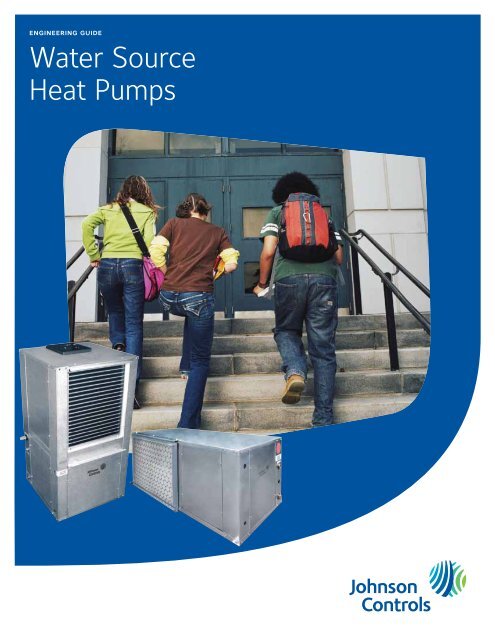
engineering guide<strong>Water</strong> SourceHeat Pumps
<strong>Water</strong> Source Heat Pumps FORM 145.00-EG4 (1209)PRODUCT OVERVIEWRefrigerantR-410ASizes.5 – 6 Tons (1.76 – 21.1 kW)ModelsRSH (Horizontal)RSV (Vertical)specificationsGENERALAll R-series models ship as factory-charged packages,complete with R-410A refrigerant. All units from ½ to 6tons shall be tested and certified by AHRI / ISO 13256-1and ETL listed for United States and Canada. AHRI /ISO and ETL labels shall be applied prior to leaving thefactory. All units are test operated at the factory.Horizontal (RSH) units are designed for suspendedceiling mounting. RSH models are shipped with ‘straightthrough’evaporator fan discharge as standard. Fanorientation is field convertible to side discharge withoutthe need for additional parts or unit modifications.Vertical (RSV) units are designed for free-standing floormounting. Vertical units are furnished with an internalcondensate trap.All units are completely factory wired and pre-piped.<strong>Water</strong> supply, water outlet, and condensate drain connectionsare via flush-mounted female NPT pipe threadfittings (no back-up wrench required).A factory-trained and employed service technician mustbe located within 50 miles of installation location.CABINETAll cabinets are completely constructed of corrosionresistant galvanized steel. The RSH units are completewith integral hanger channels. The entire unit interior(both evaporator and condensing section) is insulatedwith 1/2" thick, 2 lb density acoustical insulation.Insulation shall meet NFPA 90, UL-181, andASTM-C1071 standards, and have a flame spread ofless than 25 and a smoke developed classification ofless than 50 per ASTM E-84 and UL 723. All unitsprovide service access to the reversing valve, thermalexpansion valve, and compressor with the unit remainingin location. An integral 3/4" duct collar is providedon the blower discharge opening. The unit shall havean insulated panel separating the fan and compressorcompartments for superior sound attenuation. Separateopenings shall be provided for line voltage and lowvoltage wiring.REFRIGERATION CIRCUITSAll models shall have a sealed refrigerant circuit, utilizinghigh efficiency rotary, hermetic reciprocating or scrollcompressors. Compressors are mounted with rubberisolators on acoustically tuned bases to minimize vibrationtransmission and enhance sound performance.Internal overload protection is provided. External highpressure and low pressure cutout switches are includedin each compressor control circuit. High and lowpressure switches shall have flare (threaded) connectionsand quick connect electrical terminals, enablingeasy replacement and service. Each refrigeration circuitincludes an adjustable bi-flow thermal expansion valve(with external equalizer), bi-flow liquid line filter drier,and service gauge ports. The reversing valve is a pilotoperated, sliding piston type with a replaceable magneticsolenoid coil.The refrigerant-to-air <strong>heat</strong> transfer coils are constructedof internally enhanced copper tubes mechanicallybonded to enhanced aluminum plate fins. The evaporatorcoil is employed in a draw-through configuration.Large evaporator coil face area minimizes potentialwater blow-off. A fully-insulated, corrosion resistantcondensate sloped drain pan with condensate overflowswitch is provided as standard.• Optional anti-corrosion protective evaporator coilcoating.• Optional stainless steel drain pan.<strong>Johnson</strong> <strong>Controls</strong> 3
FORM 145.00-EG4 (1209)SPECIFIcATIONS<strong>Water</strong> Source Heat PumpsThe coaxial refrigerant-to-water <strong>heat</strong> exchangers featurea convoluted inner tube design for high <strong>heat</strong>transfer efficiency. Standard models feature a copperinner tube surrounded by a steel outer tube, and carrya 400 psig water side working pressure rating. Unitsshall be capable of operation with an entering fluidtemperature range of 20°F to 110°F.• Optional cupro-nickel condenser water coil.• Optional condenser insulation package for low-watertemperature, geothermal applications.INDOOR FANForward curved, double inlet and double width, directdrivecentrifugal blowers are used for air movement.Large diameter wheels are employed to provide requiredairflow performance at minimum sound levels. Blowerwheels are fabricated of galvanized steel. Fan motorsare PSC type, with minimum three speeds. The PSCmotors feature permanently lubricated bearings andinternal thermal overload protection.ELECTRICAL / CONTROLSAll units are completely factory wired with all necessaryoperating controls. A 24 volt control circuit, with oversizedtransformer, is provided for field connection. Thereversing valve solenoid coil shall be energized in coolingmode only.Unit shall have a microprocessor-based control systemwith the following:a. Unit shall operate with conventional thermostatdesigns.b. Unit shall incorporate a lockout circuit which providesreset capability at the space thermostat,base unit, or by interrupting service power, shouldany of the following standard safety devices tripand shut off the compressor.c. Loss-of-charge/Low-pressure switchd. High-pressure switche. Control board shall monitor each refrigerant safetyswitch independently.f. Freeze protection (Factory setting: 35F Leaving<strong>Water</strong> Temperature)g. Condensate overflow protectionh. Low voltage (brown-out) protectioni. Anti-short cycle timer (ASCT)j. Random startk. Should the high-pressure or low-pressure safetiesopen three times within two hours of operation(1 hour for low-pressure safety), then lockoutrequiring manual reset will occur.l. Should the low water temperature or condensateoverflow safeties trip 3 times sequentially, thenlockout requiring manual reset will occur.m. The low-pressure switch shall not be monitoredduring the initial 30 seconds of a cooling system’soperation to prevent nuisance trips.n. Unit shall have capability to defeat time delays forservicing.o. Unit control board shall have on-board diagnosticsand fault code display.p. Control board shall retain last 5 fault codes in nonvolatile memory which will not be lost in the eventof a power loss.q. Unit shall have an automated sequence used afterinstallation that quickly tests cooling and <strong>heat</strong>ingmodes.FILTERSAll models are shipped with 1-inch thick throwawayfilters, factory installed. Filters are accessible fromeither side of unit. Factory-installed filter rack onhorizontal units shall be adjustable from 1" to 2" withoutany additional parts or hardware.FIELD INSTALLED ACCESSORIESThe following options are available field installation:• Hose Kits (available options)• Automatic Flow Control Valve• 2 stainless steel braided flexible hoses (18"–36"lengths)• 2 manual isolation ball valves• High-flow “Y” strainer w/ blow down valve• Motorized water valve• Electronic Thermostats• Programmable (7-day), 1 Ht / 1 Cl, back-litdisplay. The thermostat shall be supplied with anoccupancy sensing cover (or be capable of beingretrofitted on site for future occupancy sensing).• Non-programmable, 1 Ht / 1 Cl, back-lit display.The thermostat shall be supplied with an occupancysensing cover (or be capable of beingretrofitted on site for future occupancy sensing).• 2" Filter Rack w/ Duct Collar• Fully sealed filter with side access• Ducted return air connection4 <strong>Johnson</strong> <strong>Controls</strong>
<strong>Water</strong> Source Heat Pumps FORM 145.00-EG4 (1209)field-installed accessoriesHose KitsTwo different types of hose kits are available:• Manual Control• Automatic Balancing Control (± 5%)High-pressure flexible hoses, with quick-sealing swivel couplings, provide supplyand return water connections to the unit. Hose material is fire-rated (UL-94 VO)thermoplastic inner tube, reinforced by a stainless steel wire outer braid. The hoseassemblies are rated for a minimum 350 psig working pressure.Thermostats<strong>Inc</strong>ludes the following features:• Programmable and non-programmable models• Onboard occupancy sensor (Passive Infrared [PIR] models)• Password protection• Backlit Liquid Crystal Display (LCD)• Simplified setpoint adjustment• Five easy-to-use interface keys• Three LEDs — fan, <strong>heat</strong>ing, and cooling status at a glance• Two configurable digital inputs• Over 20 configurable parameters• Configurable auxiliary output2" Filter RacksFor applications requiring enhanced filtration, the convenience of a 2-inch ductedreturn air filter rack is offered. This accessory provides the flexibility to utilize 2-inchthick filters. The completely sealed filter rack minimizes air bypass for improvedindoor air quality and connects to the mechanical system with a 3/4-inch fullperimeterduct flange.<strong>Johnson</strong> <strong>Controls</strong> 5
FORM 145.00-EG4 (1209)nomenclature<strong>Water</strong> Source Heat Pumps<strong>Water</strong> <strong>source</strong> <strong>heat</strong> pump1,2 3 4,5,6 7 8 9 10 11 12 13 14 15RS H 018 A 2 M L S A A 0 AProduct CategoryRS = <strong>Water</strong>-Cooled HP R-410AMiscellaneous OptionsA = NoneHeating Options0 = NoneProduct IndentifierV = Vertical Arrangement (Upflow)H = Horizontal ArrangmentNominal Capacity007 = .5 TON009 = .75 TON012 = 1 TON018 = 1.5 TON024 = 2 TON030 = 2.5 TON036 = 3 TON042 = 3.5 TON048 = 4 TON060 = 5 TON070 = 6 TONDesign SeriesA = CurrentAirside OptionsA = Std Airside coilC = Corrosion Protective CoatingD = Stainless Steel Drain PanF = Coated Coil w/ S-S Drain PanSupply Air OptionsS = Straight-Thru (Horizontal Only)B = Back Discharge (Horizontal Only)T = Top Discharge (Vertical Only)<strong>Water</strong>side OptionsA = Std <strong>Water</strong> CoilB = Std <strong>Water</strong> Coil with Low-Temp OptionN = Cupro-nickel <strong>Water</strong> CoilR = Cupro-nickel Coil with Low-Temp OptionVoltage1 = 208/230-60-16 = 265-60-12 = 208/230-60-34 = 460-60-35 = 575-60-3Return Air/Unit OrientationL = Left HandR = Right HandControl OptionsM = Std Microprocessor <strong>Controls</strong>6 <strong>Johnson</strong> <strong>Controls</strong>
<strong>Water</strong> Source Heat Pumps FORM 145.00-EG4 (1209)RSH/RSV SERIES—physical dataModel Series 007 009 012 018 024 030 036 042 048 060 070Nominal Cooling (Ton) 1 0.5 0.75 1.0 1.5 2.0 2.5 3 3.5 4 5 6Compressor-Type Rotary Reciprocating ScrollAir Coil-TypeEnhanced Copper tubes, Enhanced Aluminum FinsFace Area(sq ft) 1.17 1.17 1.33 2.56 2.88 2.88 3.47 4.44 4.44 6.11 6.11Rows/FPI 3/13 3/13 3/15 3/15 3/15 3/15 3/15 3/15 3/15 3/15 3/15<strong>Water</strong> Coil-TypeEnhanced Surface Co-Axial<strong>Water</strong> Connection (FPT) 1/2" 1/2" 1/2" 3/4" 3/4" 3/4" 3/4" 3/4" 3/4" 1" 1"Drain Connection (FPT) 3/4"Standard Blower /MotorDWDI Forward-Curved Centrifugal / PSC Direct-DriveDiameter x Width (in) 6x5 6x5 6x6 9x7 9x7 10x7T 10x7T 11x8T 11x8T 11x10T 11x10TMotor HP 0.10/3 0.10/3 0.13/3 0.17/3 0.25/3 0.33/3 0.50/3 0.50/3 0.75/3 1.0/3 1.0/3RSH FilterQuantity-Size(in)1-12x16 1-12x16 1-12x20 1-18x24 1-18x24 1-18x24 2-14x20 2-18x20 2-18x20 2-22x22 2-22x22RSV FilterQuantity-Size(in)1-12x20 1-12x20 1-12x20 1-18x24 1-20x25 1-20x25 1-24x24 2-14x25 2-14x25 2-16x30 2-16x30RSH Cabinet Weight (lb) 130 135 145 195 210 215 240 310 320 370 385RSV Cabinet Weight (lb) 120 125 135 185 200 210 230 305 315 375 390NOTE:1) Nominal Capacity calculated in accordance with AHRI / ISO Standard 13256-1 for <strong>Water</strong> Loop ApplicationOPERATING LIMITS*COOLING HEATINGMin. Entering <strong>Water</strong> 30°F 20°FMax. Entering <strong>Water</strong> 110°F 90°F*Units are capable of operation with an entering fluid temperaturerange of 20°F to 110°F*Low-Temp Option is recommended for water temperatures below40°F<strong>Johnson</strong> <strong>Controls</strong> 7
FORM 145.00-EG4 (1209)<strong>Water</strong> Source Heat Pumpsahri/iso performance dataAHRI/ISO 13256-1 WATER LOOP CONDITIONS*Unit ModelFlow Rate(USGPM)Air Flow(SCFM)CoolingCapacity (Btuh)EERHeatingCapacity (Btuh)007 1.8 260 6,800 12.5 8,700 4.5009 2.4 320 8,900 12.4 11,600 4.4012 3.0 425 12,400 12.2 15,600 4.2018 4.8 640 19,100 13.2 23,400 4.5024 6.0 800 24,600 13.5 29,300 4.4030 7.8 1000 29,800 13.3 35,300 4.5036 9.0 1200 36,200 13.0 45,100 4.6042 10.4 1400 42,700 12.7 50,600 4.4048 12.0 1600 48,300 13.1 57,200 4.5060 15.0 2000 60,500 13.4 70,800 4.6070 17.5 2200 67,700 12.9 79,500 4.3*<strong>Water</strong> Loop capacities are rated at 86°F EWT Cooling, 68°F EWT Heating.COPAHRI/ISO 13256-1 GROUND WATER CONDITIONS*Unit ModelFlow Rate(USGPM)Air Flow(SCFM)CoolingCapacity (Btuh)EERHeatingCapacity (Btuh)007 1.8 260 7,700 18.4 6,900 3.9009 2.4 320 10,100 18.3 9,100 3.8012 3.0 425 14,200 18.1 12,900 3.6018 4.8 640 22,900 20.2 18,800 3.9024 6.0 800 28,700 20.8 23,600 3.8030 7.8 1000 33,600 20.0 29,100 3.8036 9.0 1200 39,800 18.8 37,200 3.9042 10.4 1400 45,800 19.1 42,300 3.9048 12.0 1600 52,500 19.3 47,400 3.8060 15.0 2000 66,400 19.8 59,000 4.0070 17.5 2200 73,600 18.7 66,800 3.8*Ground <strong>Water</strong> capacities are rated at 59°F EWT Cooling, 50°F EWT Heating.COPAHRI/ISO 13256-1 GROUND LOOP CONDITIONS*Unit ModelFlow Rate(USGPM)Air Flow(SCFM)CoolingCapacity (Btuh)EERHeatingCapacity (Btuh)007 1.8 260 7,100 14.6 5,500 3.4009 2.4 320 9,300 14.5 6,900 3.3012 3.0 425 13,000 14.3 10,200 3.1018 4.8 640 20,600 15.7 13,900 3.4024 6.0 800 26,400 16.1 17,400 3.3030 7.8 1000 31,100 15.3 22,500 3.3036 9.0 1200 37,500 14.8 28,600 3.3042 10.4 1400 43,900 14.6 32,300 3.4048 12.0 1600 49,800 15.0 37,800 3.3060 15.0 2000 62,900 15.6 47,200 3.5070 17.5 2200 70,100 14.7 52,400 3.3*Ground Loop capacities are rated at 77°F EFT Cooling, 32°F EFT Heating.COPNOTE:1) All Cooling capacities based upon 80.6°F DB, 66.2°F WB entering air temperature.2) All Heating capacities based upon 68°F DB, 59°F WB entering air temperature.8 <strong>Johnson</strong> <strong>Controls</strong>
FORM 145.00-EG4 (1209)<strong>Water</strong> Source Heat PumpsPERFORMANCE dataRS*009 — 320 CFMEWT (F) GPMWPD COOLING HEATINGPSI FT TC SC kW HR EER HTG kW HE LAT (F) COP20 2.4 4.8 11.2 5.6 0.57 3.7 84 2.91.2 2.3 5.3 12.8 9.0 0.47 14.4 27.4 6.4 0.60 4.3 87 3.130 1.8 3.0 6.9 13.1 9.1 0.43 14.6 30.6 6.6 0.60 4.5 87 3.22.4 3.9 8.9 13.2 9.1 0.40 14.6 33.0 6.7 0.61 4.6 87 3.21.2 2.0 4.6 12.5 8.9 0.54 14.4 23.0 7.0 0.62 4.9 88 3.340 1.8 2.4 5.5 12.7 9.0 0.51 14.4 24.8 7.3 0.63 5.2 89 3.42.4 3.2 7.3 12.9 9.2 0.48 14.6 26.6 7.6 0.65 5.4 90 3.41.2 1.7 3.9 10.0 7.2 0.52 11.8 19.2 8.3 0.68 6.0 92 3.650 1.8 2.0 4.6 10.4 7.4 0.48 12.0 21.7 8.7 0.69 6.3 93 3.72.4 2.6 6.0 10.6 7.5 0.46 12.2 23.2 9.1 0.70 6.7 94 3.81.2 1.5 3.5 9.6 7.1 0.57 11.6 16.7 9.5 0.71 7.1 95 3.960 1.8 1.7 3.9 9.9 7.2 0.56 11.8 17.8 10.1 0.74 7.6 97 4.02.4 2.2 5.2 10.1 7.3 0.55 12.0 18.2 10.6 0.76 8.0 99 4.11.2 1.3 3.0 9.3 6.9 0.65 11.5 14.4 10.2 0.71 7.8 98 4.270 1.8 1.6 3.7 9.5 7.0 0.60 11.6 15.8 11.1 0.76 8.5 100 4.32.4 2.0 4.7 9.7 7.1 0.58 11.7 16.7 11.8 0.77 9.2 102 4.51.2 1.1 2.5 8.6 6.6 0.69 10.9 12.5 11.8 0.77 9.2 102 4.580 1.8 1.5 3.5 8.9 6.8 0.66 11.2 13.4 12.7 0.79 10.0 105 4.72.4 1.9 4.4 9.2 7.0 0.66 11.4 14.0 13.3 0.81 10.5 106 4.81.2 0.9 2.1 8.0 6.3 0.74 10.5 10.8 13.4 0.80 10.7 107 4.990 1.8 1.4 3.2 8.2 6.4 0.70 10.6 11.7 14.4 0.83 11.6 110 5.12.4 1.7 4.0 8.4 6.6 0.69 10.7 12.2 14.7 0.84 11.8 111 5.11.2 1.0 2.3 7.4 6.2 0.80 10.1 9.2100 1.8 1.3 3.0 7.6 6.3 0.77 10.2 9.92.4 1.6 3.7 7.8 6.4 0.76 10.4 10.31.2 0.9 2.1 8.4 7.1 1.08 12.1 7.8110 1.8 1.3 3.0 8.7 7.3 1.04 12.2 8.42.4 1.6 3.7 8.9 7.4 1.01 12.4 8.8Cooling Performance is tabulated at 80.6 F DB and 66.2 F WB entering air. Heating performance tabulated at 68 F EATTabulated data does not include AHRI/ISO corrections for fan and pump power.All capacities are expressed in MBH.Insulated water circuit is recommended for operation below 60F EWT.See performance correction tables for conditions beyond what is listed.Extrapolation is not permissible.Shaded areas indicate conditions where operation is not recommended.10 <strong>Johnson</strong> <strong>Controls</strong>
<strong>Water</strong> Source Heat Pumps FORM 145.00-EG4 (1209)PERFORMANCE dataRS*012 — 425 CFMEWT (F) GPMWPD COOLING HEATINGPSI FT TC SC kW HR EER HTG kW HE LAT (F) COP20 3.0 4.4 10.2 6.9 0.72 4.4 83 2.81.5 2.2 5.0 16.9 11.8 0.53 18.7 32.0 8.0 0.76 5.4 85 3.130 2.3 2.9 6.8 17.1 11.9 0.49 18.8 34.7 8.3 0.76 5.7 86 3.23.0 3.8 8.8 17.2 11.9 0.48 18.8 36.0 8.4 0.77 5.8 86 3.21.5 1.9 4.4 16.2 11.6 0.63 18.3 25.8 9.2 0.79 6.5 88 3.440 2.3 2.6 5.9 16.5 11.7 0.60 18.5 27.6 9.5 0.80 6.8 89 3.53.0 3.3 7.6 16.6 11.8 0.58 18.6 28.7 9.6 0.80 6.9 89 3.51.5 1.6 3.7 15.5 11.2 0.74 18.0 21.0 10.3 0.82 7.5 90 3.750 2.3 2.2 5.0 15.8 11.3 0.71 18.2 22.3 10.7 0.85 7.8 91 3.73.0 2.8 6.5 15.9 11.3 0.69 18.2 23.1 11.1 0.86 8.2 92 3.81.5 1.4 3.2 14.9 11.0 0.85 17.8 17.6 11.7 0.88 8.7 93 3.960 2.3 1.9 4.3 15.1 11.0 0.81 17.9 18.6 12.2 0.89 9.2 95 4.03.0 2.4 5.5 14.2 10.3 0.79 16.9 18.0 12.5 0.89 9.5 95 4.11.5 1.3 2.9 13.1 9.8 0.89 16.1 14.8 13.0 0.91 9.9 96 4.270 2.3 1.7 3.9 13.4 9.8 0.86 16.3 15.6 13.3 0.91 10.2 97 4.33.0 2.2 5.1 13.5 9.9 0.84 16.4 16.1 14.1 0.92 11.0 99 4.51.5 1.1 2.6 12.1 9.4 0.98 15.5 12.3 14.7 0.94 11.5 100 4.680 2.3 1.6 3.6 12.5 9.6 0.96 15.8 13.0 15.4 0.96 12.1 102 4.73.0 2.0 4.6 12.8 9.8 0.95 16.0 13.5 15.9 0.97 12.6 103 4.81.5 1.0 2.4 11.8 9.3 1.11 15.6 10.6 16.1 0.98 12.7 103 4.890 2.3 1.4 3.2 12.0 9.4 1.08 15.7 11.1 16.9 0.99 13.5 105 5.03.0 1.8 4.2 12.2 9.6 1.06 15.8 11.5 17.6 1.01 14.1 106 5.11.5 1.0 2.2 10.9 9.1 1.21 15.0 9.0100 2.3 1.3 3.0 11.3 9.4 1.19 15.4 9.53.0 1.7 3.9 11.5 9.5 1.17 15.5 9.81.5 1.0 2.2 10.0 8.5 1.32 14.5 7.6110 2.3 1.3 3.0 10.3 8.7 1.29 14.7 8.03.0 1.7 3.9 10.6 8.8 1.28 15.0 8.3Cooling Performance is tabulated at 80.6 F DB and 66.2 F WB entering air. Heating performance tabulated at 68 F EATTabulated data does not include AHRI/ISO corrections for fan and pump power.All capacities are expressed in MBH.Insulated water circuit is recommended for operation below 60F EWT.See performance correction tables for conditions beyond what is listed.Extrapolation is not permissible.Shaded areas indicate conditions where operation is not recommended.<strong>Johnson</strong> <strong>Controls</strong> 11
FORM 145.00-EG4 (1209)<strong>Water</strong> Source Heat PumpsPERFORMANCE dataRS*018 — 640 CFMEWT (F) GPMWPD COOLING HEATINGPSI FT TC SC kW HR EER HTG kW HE LAT (F) COP20 4.8 8.2 18.9 10.4 1.09 6.7 83 2.82.4 3.0 7.0 26.6 18.6 0.96 29.9 27.7 12.0 1.17 8.0 85 3.030 3.6 4.8 11.1 27.3 19.1 0.90 30.4 30.2 12.4 1.21 8.3 86 3.04.8 7.2 16.6 27.7 19.1 0.87 30.7 32.0 12.7 1.20 8.6 86 3.12.4 2.7 6.1 24.9 17.7 1.05 28.5 23.8 14.7 1.23 10.5 89 3.540 3.6 4.2 9.7 25.6 18.0 1.00 29.0 25.5 15.2 1.27 10.9 90 3.54.8 6.3 14.6 25.9 18.1 0.96 29.2 27.0 15.7 1.28 11.3 91 3.62.4 2.3 5.4 24.3 17.5 1.15 28.2 21.1 17.3 1.33 12.7 93 3.850 3.6 3.7 8.5 24.5 17.5 1.14 28.4 21.5 18.0 1.35 13.4 94 3.94.8 5.5 12.7 24.9 17.7 1.09 28.6 22.8 18.8 1.41 14.0 95 3.92.4 2.0 4.6 21.3 15.7 1.22 25.5 17.4 19.2 1.41 14.4 96 4.060 3.6 3.1 7.2 22.0 16.1 1.21 26.1 18.2 20.1 1.44 15.2 97 4.14.8 4.7 10.9 22.8 16.6 1.13 26.7 20.2 20.8 1.45 15.8 98 4.22.4 1.7 3.9 20.2 15.0 1.34 24.8 15.1 22.0 1.47 17.0 100 4.470 3.6 2.7 6.2 20.5 15.1 1.27 24.8 16.2 23.1 1.50 18.0 101 4.54.8 4.0 9.2 21.0 15.3 1.24 25.2 17.0 23.9 1.56 18.6 103 4.52.4 1.5 3.4 18.6 14.4 1.44 23.5 12.9 23.3 1.48 18.2 102 4.680 3.6 2.3 5.4 19.3 14.8 1.39 24.0 13.9 24.6 1.50 19.5 104 4.84.8 3.5 8.1 19.8 15.1 1.37 24.5 14.5 25.4 1.51 20.2 105 4.92.4 1.4 3.1 17.4 13.7 1.55 22.7 11.2 25.8 1.49 20.7 105 5.190 3.6 2.1 4.9 18.1 14.2 1.52 23.3 11.9 27.0 1.52 21.8 107 5.24.8 3.2 7.4 18.6 14.6 1.50 23.7 12.4 28.1 1.55 22.8 109 5.32.4 1.3 3.0 16.6 13.8 1.84 22.9 9.7100 3.6 2.1 4.8 17.2 14.3 1.82 23.4 10.34.8 3.1 7.2 17.7 14.6 1.79 23.8 10.62.4 1.3 2.9 15.1 13.1 1.91 21.6 8.4110 3.6 2.0 4.6 15.8 13.5 1.87 22.2 8.94.8 3.0 6.9 16.1 13.5 1.84 22.4 9.2Cooling Performance is tabulated at 80.6 F DB and 66.2 F WB entering air. Heating performance tabulated at 68 F EATTabulated data does not include AHRI/ISO corrections for fan and pump power.All capacities are expressed in MBH.Insulated water circuit is recommended for operation below 60F EWT.See performance correction tables for conditions beyond what is listed.Extrapolation is not permissible.Shaded areas indicate conditions where operation is not recommended.12 <strong>Johnson</strong> <strong>Controls</strong>
<strong>Water</strong> Source Heat Pumps FORM 145.00-EG4 (1209)PERFORMANCE dataRS*024 — 800 CFMEWT (F) GPMWPD COOLING HEATINGPSI FT TC SC kW HR EER HTG kW HE LAT (F) COP20 6.0 9.6 22.2 13.3 1.50 8.2 83 2.63.0 3.5 8.1 35.1 24.6 1.07 38.8 32.7 15.9 1.50 10.8 86 3.130 4.5 5.3 12.3 35.9 25.0 1.01 39.4 35.4 16.4 1.50 11.3 87 3.26.0 8.5 19.6 36.4 25.2 0.99 39.8 36.8 16.8 1.54 11.6 87 3.23.0 3.1 7.2 33.4 23.9 1.13 37.3 29.5 18.4 1.59 13.0 89 3.440 4.5 4.8 11.0 34.3 24.4 1.07 37.9 32.1 19.1 1.60 13.6 90 3.56.0 7.6 17.6 34.8 24.7 1.04 38.4 33.4 19.7 1.60 14.2 91 3.63.0 2.7 6.3 31.4 22.6 1.30 35.8 24.2 21.6 1.71 15.8 93 3.750 4.5 4.1 9.6 32.2 23.0 1.23 36.4 26.1 22.6 1.79 16.5 94 3.76.0 6.6 15.2 32.8 23.3 1.21 36.9 27.0 23.6 1.82 17.4 95 3.83.0 2.4 5.6 27.8 20.4 1.49 32.9 18.7 25.1 1.71 19.3 97 4.360 4.5 3.7 8.6 28.4 20.7 1.48 33.4 19.2 26.4 1.72 20.5 99 4.56.0 5.9 13.6 29.0 21.1 1.45 33.9 20.0 27.4 1.78 21.3 100 4.53.0 2.1 4.9 27.2 20.3 1.64 32.8 16.6 27.8 1.77 21.8 100 4.670 4.5 3.3 7.5 28.0 20.6 1.60 33.5 17.5 29.3 1.83 23.1 102 4.76.0 5.2 12.0 28.5 20.8 1.56 33.8 18.3 30.4 1.86 24.1 103 4.83.0 1.9 4.5 24.8 19.2 1.77 30.8 14.0 31.5 1.85 25.2 104 5.080 4.5 2.9 6.8 25.1 19.3 1.70 30.9 14.8 31.8 1.86 25.4 105 5.06.0 4.7 10.9 26.0 19.9 1.70 31.8 15.3 33.0 1.90 26.5 106 5.13.0 1.8 4.2 23.1 18.2 1.96 29.8 11.8 32.1 1.84 25.8 105 5.190 4.5 2.8 6.4 23.9 18.8 1.90 30.4 12.6 33.9 1.91 27.4 107 5.26.0 4.4 10.2 24.4 19.1 1.86 30.8 13.1 35.3 1.95 28.6 109 5.33.0 1.7 4.0 20.6 17.2 2.06 27.6 10.0100 4.5 2.6 6.1 21.6 17.9 2.04 28.6 10.66.0 4.2 9.7 22.1 18.3 2.01 29.0 11.03.0 1.7 3.9 18.7 15.9 2.17 26.1 8.6110 4.5 2.6 5.9 19.5 16.4 2.14 26.8 9.16.0 4.1 9.5 20.0 16.6 2.13 27.3 9.4Cooling Performance is tabulated at 80.6 F DB and 66.2 F WB entering air. Heating performance tabulated at 68 F EATTabulated data does not include AHRI/ISO corrections for fan and pump power.All capacities are expressed in MBH.Insulated water circuit is recommended for operation below 60F EWT.See performance correction tables for conditions beyond what is listed.Extrapolation is not permissible.Shaded areas indicate conditions where operation is not recommended.<strong>Johnson</strong> <strong>Controls</strong> 13
FORM 145.00-EG4 (1209)<strong>Water</strong> Source Heat PumpsPERFORMANCE dataRS*030 — 1000 CFMEWT (F) GPMWPD COOLING HEATINGPSI FT TC SC kW HR EER HTG kW HE LAT (F) COP20 7.8 10.9 25.2 17.5 1.97 10.8 84 2.63.9 6.2 14.2 38.6 27.0 1.43 43.5 26.9 19.2 1.88 12.8 86 3.030 5.8 7.8 18.0 39.5 27.5 1.41 44.3 28.0 20.3 1.92 13.8 87 3.17.8 9.7 22.4 40.0 27.7 1.39 44.8 28.7 22.0 2.01 15.1 88 3.23.9 5.5 12.6 37.1 26.5 1.53 42.3 24.2 22.3 1.87 15.9 89 3.540 5.8 6.9 16.0 38.0 27.1 1.49 43.1 25.5 23.2 1.94 16.6 89 3.57.8 8.6 19.9 38.6 27.4 1.48 43.6 26.1 23.9 1.95 17.3 90 3.63.9 4.9 11.3 34.4 24.8 1.65 40.0 20.8 27.1 2.15 19.8 93 3.750 5.8 6.2 14.3 35.2 25.2 1.62 40.7 21.7 28.2 2.23 20.6 94 3.77.8 7.7 17.8 35.8 25.4 1.55 41.1 23.1 29.1 2.24 21.4 95 3.83.9 4.3 10.0 32.1 23.6 1.75 38.1 18.3 29.5 2.11 22.3 95 4.160 5.8 5.5 12.6 32.9 24.0 1.70 38.7 19.3 30.9 2.16 23.5 97 4.27.8 6.8 15.7 33.5 24.4 1.70 39.3 19.7 32.0 2.18 24.6 98 4.33.9 3.9 8.9 31.0 23.1 1.86 37.3 16.7 33.1 2.20 25.6 99 4.470 5.8 4.9 11.3 31.8 23.4 1.82 38.0 17.5 34.7 2.26 27.0 100 4.57.8 6.1 14.1 32.3 23.6 1.80 38.5 17.9 36.0 2.34 28.0 101 4.53.9 3.5 8.1 29.0 22.4 2.04 36.0 14.2 36.4 2.32 28.5 102 4.680 5.8 4.4 10.2 29.7 22.8 2.01 36.5 14.8 38.2 2.38 30.1 103 4.77.8 5.5 12.7 30.2 23.1 2.00 37.0 15.1 39.7 2.42 31.4 105 4.83.9 3.3 7.6 28.0 22.1 2.33 36.0 12.0 40.7 2.43 32.4 106 4.990 5.8 4.2 9.7 28.7 22.5 2.30 36.5 12.5 42.8 2.51 34.2 108 5.07.8 5.2 12.0 29.2 22.9 2.28 37.0 12.8 44.5 2.56 35.8 109 5.13.9 3.2 7.3 25.8 21.5 2.50 34.3 10.3100 5.8 4.0 9.3 26.5 22.0 2.45 34.9 10.87.8 5.0 11.6 27.0 22.3 2.45 35.4 11.03.9 3.0 6.9 23.6 20.1 2.65 32.7 8.9110 5.8 3.9 9.1 24.3 20.5 2.64 33.3 9.27.8 4.8 11.1 24.7 20.5 2.63 33.7 9.4Cooling Performance is tabulated at 80.6 F DB and 66.2 F WB entering air. Heating performance tabulated at 68 F EATTabulated data does not include AHRI/ISO corrections for fan and pump power.All capacities are expressed in MBH.Insulated water circuit is recommended for operation below 60F EWT.See performance correction tables for conditions beyond what is listed.Extrapolation is not permissible.Shaded areas indicate conditions where operation is not recommended.14 <strong>Johnson</strong> <strong>Controls</strong>
<strong>Water</strong> Source Heat Pumps FORM 145.00-EG4 (1209)PERFORMANCE dataRS*036 — 1200 CFMEWT (F) GPMWPD COOLING HEATINGPSI FT TC SC kW HR EER HTG kW HE LAT (F) COP20 9.0 12.1 28.0 19.9 1.94 2.0 83 3.04.5 4.4 10.1 45.6 31.9 1.27 49.9 35.9 23.2 2.06 16.2 86 3.330 6.8 8.1 18.7 47.5 33.1 1.26 51.8 37.8 24.0 2.13 16.7 86 3.39.0 11.0 25.4 48.8 33.8 1.26 53.1 38.8 24.5 2.11 17.3 87 3.44.5 3.9 9.1 44.0 31.5 1.44 48.9 30.6 28.2 2.23 20.6 90 3.740 6.8 7.3 16.8 45.0 32.0 1.40 49.8 32.2 29.4 2.27 21.7 91 3.89.0 9.9 22.9 45.7 32.4 1.38 50.4 33.1 30.2 2.33 22.3 91 3.84.5 3.6 8.2 41.7 30.0 1.72 47.6 24.3 34.0 2.43 25.7 94 4.150 6.8 6.6 15.3 42.8 30.6 1.67 48.5 25.7 35.6 2.48 27.1 95 4.29.0 9.0 20.8 43.3 30.7 1.64 48.9 26.4 37.2 2.58 28.4 97 4.24.5 3.2 7.4 38.0 27.9 1.84 44.3 20.7 37.6 2.50 29.1 97 4.460 6.8 6.0 13.8 38.9 28.4 1.79 45.0 21.8 39.5 2.57 30.7 98 4.59.0 8.1 18.7 39.6 28.8 1.77 45.6 22.4 40.8 2.66 31.7 99 4.54.5 2.9 6.8 34.4 25.6 2.02 41.3 17.0 41.5 2.64 32.5 100 4.670 6.8 5.4 12.6 35.3 25.9 1.97 42.0 17.9 43.7 2.72 34.4 102 4.79.0 7.4 17.1 36.0 26.3 1.96 42.7 18.4 45.3 2.77 35.9 103 4.84.5 2.7 6.2 36.1 27.9 2.56 44.8 14.1 46.7 2.85 37.0 104 4.880 6.8 5.0 11.6 36.5 28.0 2.50 45.0 14.6 49.1 2.94 39.1 106 4.99.0 6.8 15.7 37.1 28.3 2.69 46.3 13.8 50.4 3.04 40.0 107 4.94.5 2.5 5.9 34.9 27.5 2.96 45.0 11.8 50.8 2.98 40.6 107 5.090 6.8 4.7 10.9 35.4 27.7 2.90 45.2 12.2 53.6 3.08 43.1 109 5.19.0 6.4 14.8 35.6 27.9 2.87 45.4 12.4 55.6 3.13 44.9 111 5.24.5 2.5 5.7 32.8 27.4 3.16 43.6 10.4100 6.8 4.6 10.5 33.3 27.6 3.11 43.9 10.79.0 6.2 14.3 33.5 27.6 3.10 44.0 10.84.5 2.4 5.5 31.7 26.9 3.37 43.2 9.4110 6.8 4.4 10.2 32.1 27.1 3.31 43.4 9.79.0 6.0 13.9 32.4 26.9 3.30 43.6 9.8Cooling Performance is tabulated at 80.6 F DB and 66.2 F WB entering air. Heating performance tabulated at 68 F EATTabulated data does not include AHRI/ISO corrections for fan and pump power.All capacities are expressed in MBH.Insulated water circuit is recommended for operation below 60F EWT.See performance correction tables for conditions beyond what is listed.Extrapolation is not permissible.Shaded areas indicate conditions where operation is not recommended.<strong>Johnson</strong> <strong>Controls</strong> 15
<strong>Water</strong> Source Heat Pumps FORM 145.00-EG4 (1209)dimensional dataLEFT HAND RETURNrSH seriesRIGHT HAND RETURNØ0.875"GRETURNAIRTOPVIEWRETURNAIRGØ0.875"EBOPTIONALSIDEDISCHARGEOPTIONALSIDEDISCHARGEBE0.75"TYPDSUPPLYAIRSUPPLYAIRDA0.75"TYPALKKL1.63"C2MELEVATIONVIEW2C0.75"0.75"2.00"POWERCONNECTION1.63"POWERCONNECTIONJWATER OUT15.00FRONTVIEWMWATER OUT15.00"PP1.50"WATER INLOW VOLTAGECONNECTION2.18"WATER INLOW VOLTAGECONNECTION2.18"NBACKVIEW2.00"N31.63"31.00"3/4 FPTDRAIN3.38"SERVICE DOORS1 - ELECTRICAL BOX SERVICE DOOR2 - COMPRESSOR AND CONDENSERSERVICE DOOR3 - BLOWER SERVICE DOOR1.50"J3.38"3/4 FPTDRAIN1.00"1.63"Model A B C D ERETURN AIRSUPPLY AIRKG J L MN PRSH007 34.00 19.00 13.00 31.75 21.50 16.50 10.50 6.75 7.25 6.00 6.07 2.50RSH009 34.00 19.00 13.00 31.75 21.50 16.50 10.50 6.75 7.25 6.00 6.07 2.50RSH012 34.00 19.00 13.00 31.75 21.50 18.50 10.50 6.75 7.25 6.00 6.07 2.50RSH018 40.00 21.00 19.00 37.75 23.50 23.00 16.50 6.50 9.19 10.31 3.75 2.80RSH024 44.00 21.00 19.00 41.75 23.50 24.50 16.50 6.50 9.19 10.31 4.81 2.80RSH030 44.00 21.00 19.00 41.75 23.50 24.50 16.50 6.50 9.69 11.38 4.81 2.80RSH036 48.00 22.00 21.00 45.75 24.50 27.50 18.50 6.50 9.69 11.38 5.88 2.80RSH042 52.00 26.00 21.00 49.75 28.50 35.50 18.50 6.50 10.50 13.63 5.88 2.80RSH048 52.00 26.00 21.00 49.75 28.50 35.50 18.50 6.50 10.50 13.63 5.13 2.80RSH060 56.00 26.00 23.00 53.75 28.50 43.50 20.50 6.00 13.12 13.63 5.13 3.06RSH070 56.00 26.00 23.00 53.75 28.50 43.50 20.50 6.00 13.12 13.63 5.13 3.06ALL DIMENSIONS IN INCHES<strong>Johnson</strong> <strong>Controls</strong> 23
FORM 145.00-EG4 (1209)dimensional data<strong>Water</strong> Source Heat PumpsLEFT HAND RETURNRSV RVS series SERIESRIGHT HAND RETURNTOP VIEWSERVICE DOORS1 - ELECTRICAL BOX SERVICE DOOR2 - CONDENSER SERVICE DOOR(COMPRESSOR ACCESS OPPOSITE SIDE)3 - BLOWER SERVICE DOORTOP VIEWAIR SUPPLYAIR SUPPLY2"2"33RETURN AIRRETURN AIRDRAIN3/4" FPTDRAIN3/4" FPTR5"P1WATER OUTWATER IN2.18"POWERCONNECTIONLOW VOLTAGECONNECTIONCOMPRESSORACCESS DOORPOWERCONNECTIONLOW VOLTAGECONNECTIONCOMPRESSORACCESS DOOR1WATER OUTWATER IN2.18"P5"RBBAIR COIL SIDEModel A B CSUPPLY AIRRETURN AIRFL FR GD E K LP RRSV007 21.50 21.50 31.50 7.25 6.00 2.00 8.56 7.13 20.00 10.50 2.50 16.25RSV009 21.50 21.50 31.50 7.25 6.00 2.00 8.56 7.13 20.00 10.50 2.50 16.25RSV012 21.50 21.50 31.50 7.25 6.00 2.00 8.56 7.13 20.00 10.50 2.50 16.12RSV018 25.50 23.00 40.00 9.19 10.31 2.00 6.00 8.16 25.00 16.50 2.75 18.56RSV024 25.50 23.00 40.00 9.19 10.31 2.00 6.00 8.16 25.00 18.50 2.75 17.12RSV030 25.50 23.00 40.00 9.69 11.38 2.00 5.00 7.91 25.00 18.50 2.75 17.12RSV036 25.50 23.00 44.00 9.69 11.38 2.00 5.00 7.91 25.00 22.50 2.75 17.00RSV042 28.00 25.50 46.00 10.50 13.63 2.00 5.00 8.75 23.00 26.00 2.75 15.25RSV048 28.00 25.50 46.00 10.50 13.63 2.00 5.00 8.75 23.00 26.00 2.75 15.25RSV060 32.50 27.50 50.00 13.12 13.63 3.00 6.00 9.69 28.00 30.00 3.06 15.00RSV070 32.50 27.50 50.00 13.12 13.63 3.00 6.00 9.69 28.00 30.00 3.06 15.00ALL DIMENSIONS IN INCHES24 <strong>Johnson</strong> <strong>Controls</strong>
<strong>Water</strong> Source Heat Pumps FORM 145.00-EG4 (1209)WIRING DIAGRAMrsh/rsv series; 208-230V/1Ph/60Hz265v/1ph/60hz<strong>Johnson</strong> <strong>Controls</strong> 25
FORM 145.00-EG4 (1209)WIRING DIAGRAM<strong>Water</strong> Source Heat Pumpsrsh/rsv series; 208-230V/3Ph/60Hz26 <strong>Johnson</strong> <strong>Controls</strong>
<strong>Water</strong> Source Heat Pumps FORM 145.00-EG4 (1209)WIRING DIAGRAMrsh/rsv series; 460-575V/3Ph/60Hz<strong>Johnson</strong> <strong>Controls</strong> 27
Printed on recycled paperForm: 145.00-EG4 (1209) Supersedes: 145.00-EG4 (309)© 2008 <strong>Johnson</strong> <strong>Controls</strong>, <strong>Inc</strong>. P.O. Box 423, Milwaukee, WI 53201 Printed in USAwww.johnsoncontrols.com