Air-Cooled Screw Liquid Chillers - Usair-eng.com
Air-Cooled Screw Liquid Chillers - Usair-eng.com
Air-Cooled Screw Liquid Chillers - Usair-eng.com

You also want an ePaper? Increase the reach of your titles
YUMPU automatically turns print PDFs into web optimized ePapers that Google loves.
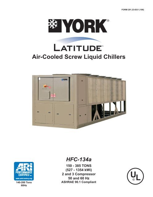
FORM 201.23-EG1 (108)<strong>Air</strong>-<strong>Cooled</strong> <strong>Screw</strong> <strong>Liquid</strong> <strong>Chillers</strong>140-200 Tons60HzHFC-134a150 - 385 TONS(527 - 1354 kWi)2 and 3 Compressor50 and 60 HzASHRAE 90.1 Compliant
IntroductionFORM 201.23-EG1 (108)YORK YCIV <strong>Air</strong>-<strong>Cooled</strong> <strong>Screw</strong> <strong>Liquid</strong> <strong>Chillers</strong>YORK has a proud history of innovation in both <strong>com</strong>pressor design and variable-speed-drive (VSD)technology. The Latitude TM air-cooled chiller uses the best of modern screw <strong>com</strong>pressor designand manufacturing techniques and <strong>com</strong>bines them with the latest in a long line of chiller variablespeed drives. The result is superior control and industry leading efficiency at real world conditions.In addition, by slowing the speed of the chiller to match system requirements at off-design conditions,the chiller sound output is reduced when it is the most sensitive to neighbors – evenings andweekends.With the introduction of the YCIV model air-cooled chiller, system designers are given the Latitudetodesign around the traditional benefits of air-cooled chillers and still offer building owners energy efficientsystem design. In the past, the choice to use an air-cooled chiller came with the expectationof <strong>com</strong>promise, where simplicity of design and maintenance were traded for performance and efficiency.Now <strong>com</strong>bining the best of both worlds can provide a design that truly delivers the lowesttotal cost of ownership.JOHNSON CONTROLS
SpecificationsPOWER AND ELECTRICAL• Johnson Controls has over 25 years of experiencedesigning variable speed drives specifically for chillerapplications. The result is an extremely reliable aircooledchiller system that offers industry leading efficiencyat real world operating conditions, valve-less<strong>com</strong>pressor loading/unloading, excellent capacitycontrol, high power factor and soft start.• All controls and motor starting equipment necessaryfor unit operation shall be factory wired and functiontested.• VSD Power/Control Panel includes main powerconnection(s), VSD and fan motor contactors, currentoverloads, and factory wiring. Standard designincludes NEMA 3R (IP55) rating, powder painted steelcabinet with hinged, latched, and gasket sealed outerdoors equipped with wind struts for safer servicing.• VSD section of power panel includes a dedicatedinverter for each <strong>com</strong>pressor.• The panel includes control display access door sodisplay and control features can be accessed withoutopening main cabinet doors.• Two and three <strong>com</strong>pressor models <strong>com</strong>e standard withsingle point power connection. In addition, all modelsare supplied with a factory mounted and wired controltransformer that will supply all unit control voltage fromthe main unit power supply. The transformer utilizesscheduled line voltage on the primary side and provides115V/1Ø on secondary.• The standard power panel is equipped with terminalblock electrical connections at the point of in<strong>com</strong>ingpower. An optional factory mounted circuit breaker isavailable, at point of in<strong>com</strong>ing single point connection,that provides the means to disconnect power and shortcircuit protection. The optional lockable operatinghandle extends through the power panel door so thatpower may be disconnected without opening any paneldoors.• Short Circuit Withstand Rating of the chiller electricalenclosure is 30,000 Amps for standard terminalblock connection. Ratings IAW (in accordance with)UL508. (See Accessories and Options section: Canbe increased to 65,000 Amps for 380, 400 & 460V).• Compressor motors are powered by a variable speeddrive. Therefore, motor current never exceeds therated load amps (RLA), providing soft starts with noelectrical inrush. This eliminates the motor heatingand stress always found with conventional motorstarters. In addition, by eliminating the heat build upduring starting, the required off-time between starts isreduced to a maximum of two minutes.• Many utility <strong>com</strong>panies charge an additional feeif power factor is below 0.95. These power factoradjustments/penalties can affect both regular tariffrates, as well as demand charges. All YCIV modelshave a full load power factor of 95% and maintain thislevel throughout the operating range. Specificationsshould always require the installing contractor to beresponsible for additional cost to furnish and installpower factor correction capacitors if they are not factorymounted and wired.S E M I - H E R M E T I C Y O R K T W I N S C R E WCOMPRESSORSJohnson Controls Engineered Systems’ Chiller DesignTeam has developed a world class <strong>com</strong>pressor with unequaledperformance:• Continuous function, microprocessor controlled, VSDprovides valveless, smooth capacity control from 100%down to 10% of chiller capacity for two <strong>com</strong>pressorchillers and 100% down to 7.5% for three <strong>com</strong>pressorchillers. In addition, elimination of the slide valve andassociated unloading <strong>com</strong>ponents resulted in a 50%reduction in <strong>com</strong>pressor moving parts.• Compressors are direct drive, semihermetic, rotarytwin-screw type, including: muffler, temperature actuated‘off-cycle’ heater, rain-tight (IP55) terminalbox, discharge shut-off service valve, and precisionmachined cast iron housing mounted on neopreneisolators.• Reliable suction gas cooled, high efficiency, accessiblehermetic <strong>com</strong>pressor motor, full suction gas flowthrough 0.006” maximum mesh screen, with inherentinternal thermal overload protection and external currentoverload on all three phases.• Suction gas screen and serviceable, 0.5 micron fullflow oil filter within the <strong>com</strong>pressor housing.• Cast iron <strong>com</strong>pressor housing precisely machinedfor optimal clearances and superb efficiency. Entire<strong>com</strong>pressor, from suction to discharge has a DesignWorking Pressure of 350 PSIG (24 bar) or higher.REFRIGERANT CIRCUIT• Independent refrigerant circuits per <strong>com</strong>pressor, eachusing copper refrigerant pipe formed on <strong>com</strong>putercontrolled bending machines. This eliminates over60% of system piping brazed joints as <strong>com</strong>pared todesigns that use fittings, resulting in a highly reliableand leak resistant system.• <strong>Liquid</strong> line <strong>com</strong>ponents include: liquid line shut-offvalve with charging port, low side pressure relief device,high adsorption removable core filter-drier, sightglass with moisture-indicator, and electronic expansionvalve.JOHNSON CONTROLS
FORM 201.23-EG1 (108)• Discharge line provided with manual <strong>com</strong>pressorshutoff service valve (See Options and Accessories forsuction line valve). Suction line equipped with closedcellinsulation.• Insulated external oil separators with no moving parts,450 PSIG (31 bar) design working pressure, and ULlisting. Refrigerant system differential pressure providesoil flow through service replaceable, 0.5 micron,full flow, cartridge type oil filter internal to <strong>com</strong>pressor.• Oil cooling provided by dedicated air-cooled finnedtube type heat exchanger located in the condensersection of the machine.• A flash tank is located in each refrigerant circuit toincrease the system efficiency. The design workingpressure is 450 PSIG (31 bar).• Suction lines, oil separators and flash tanks are coveredwith closed-cell insulation.EVAPORATOR• High efficiency, direct-expansion type cooler with refrigerantin tubes and chilled liquid through the baffledshell. Independent circuits provided for each <strong>com</strong>pressor.• Design working pressure of the shell waterside is 150PSIG (10.3 bar), and 235 PSIG (16 bar) for the refrigerantside. Constructed and tested IAW applicablesections of ASME Pressure Vessel Code, Section VIII,Division (1). Water side exempt per paragraph U-1, ©,(6).• Removable heads allow access to internally-enhanced,seamless, copper tubes. Water vent and drainconnections included.• The evaporator is equipped with a thermostaticallycontrolled heater for protection to -20°F (-29°C) ambient,and shell is covered with 3/4” (19mm), flexible,closed-cell insulation, thermal conductivity of 0.26k(BTU/HR-Ft 2 -°F/in.) maximum.• Water nozzles have grooves for mechanical (ANSI/AWWA C-606) couplings, and shall be insulated byContractor after pipe installation. (See the Accessoriesand Options section for flange options.CONDENSER SECTION• Condenser fans are dynamically and statically balanced,direct drive, corrosion resistant glass fiberreinforced <strong>com</strong>posite blades molded into low noise,full airfoil cross section, providing vertical air dischargefrom extended orifices. Guards of heavy gauge, PVC(polyvinyl chloride) coated.• Standard and reduced sound level models havecondensers fitted with single speed fans. Low soundmodels have two speed fans fitted.• The fan motors are the high efficiency, direct drive, 6pole on standard sound models and 8 pole on reducedand low sound models, 3 phase, Class-“F”, currentoverload protected, totally enclosed (TEAO) type withdouble sealed, permanently lubricated, ball bearings• Fin and tube condenser coils of seamless, internallyenhanced, high condensing coefficient, corrosion resistantcopper tubes arranged in staggered rows andmechanically bonded to corrosion resistant aluminumalloy fins with full height fin collars. Design workingpressure is 450 PSIG (31 bar).MICROPROCESSOR CONTROLS• Microprocessor control system provides automaticcontrol of chiller operation including <strong>com</strong>pressor start/stop and load/unload, anti-recycle timers, condenserfans, evaporator pump, evaporator heater, unit alarmcontacts and run signal contacts.• Chiller automatically resets to normal chiller operationafter power failure.• Unit operating software is stored in non-volatilememory. Field programmed set points are retainedin lithium battery backed regulated time clock (RTC)memory for minimum 5 years.• Alarm contacts are provided to remote alert contactsfor any unit or system safety fault.• Display and Keypad:♦ 80 character liquid crystal display that is both viewablein direct sunlight and has LED backlighting fornighttime viewing. One keypad and display panelis provided with every chiller.♦ Display and keypad is accessible through displayaccess door without opening main control/electricalcabinet doors.♦ Display provides unit setpoints, status, electricaldata, temperature data, pressures, safety lockoutsand diagnostics without the use of a codeddisplay.♦ Descriptions in English (or available language options),numeric data in English (or Metric) units.♦ Sealed keypad shall include unit On/Off switch.• Programmable Setpoints (within Manufacturer limits):display language; leaving chilled liquid temperature:setpoint, control range; local or remote control; units ofmeasure; <strong>com</strong>pressor lead/lag; and maximum chilledwater setpoint reset temperature range.• Display Data: Chiller liquid return and leaving temperatures,ambient, lead <strong>com</strong>pressor identification, clockJOHNSON CONTROLS
Specifications – continuedand schedule, (variable) out of range, remote inputindication, chilled liquid reset setpoint, and historydata for last ten shutdown faults. Compressor suction,discharge, and oil pressures and temperatures,suction and discharge superheats, percent of full-load,operating hours, starts, and anti-recycle timer status.Status Messages for manual override, unit switch off,<strong>com</strong>pressor run, run permissive, remote controlledshut down, no cooling load, daily/holiday shut down,anti-recycle timer.• During extreme or unusual conditions (i.e. blockedcondenser coils, ambient above scheduled maximum,etc.) the chiller control system will avoid safety shutdownby varying the chiller controls and cooling loadoutput to stay online and avoid safety limits beingreached. This allows maximum possible cooling capacityuntil the unusual condition is cleared and avoidscostly shutdowns. The system monitors the followingparameters and maintain the maximum cooling outputpossible without shutdown of the equipment: motorcurrent, suction pressure and discharge pressure.• System Safeties are provided for individual <strong>com</strong>pressorsystems to perform auto-reset shut down (manualreset required after the third trip in 90 minutes). Safetiesinclude: high discharge pressure or temperature,low suction pressure, high / low motor current, highmotor temperature, high pressure switch, high / lowdifferential oil pressure, high oil temperature, low suctionsuperheat, critical sensor malfunction, low or highcurrent, phase loss/single phase power, overload ofmotor windings, and low voltage.• Unit Safeties are provided for the chiller to performauto-reset shut down for the following conditions: highor low ambient, low leaving chilled liquid temperature,under voltage, and flow switch operation.COMPLETE FACTORY PACKAGE• These air-cooled chillers are shipped as a <strong>com</strong>pletefactory package. Each unit is <strong>com</strong>pletely assembledwith all interconnecting refrigerant piping and internalwiring, ready for field installation:• Each <strong>com</strong>pressor is installed on its own independentrefrigerant circuit, which is factory pressure tested,evacuated, then fully charged with R134a refrigerantand oil.• After assembly, an operational test is performed withwater flowing through the cooler to ensure each circuitoperates correctly.• Unit panels, structural elements, control boxes andheavy gauge structural base shall be constructedof galvanized steel. Unit panels, control boxes andstructural base are finished with a baked on powderpaint. All painted surfaces shall be coated with bakedon powder paint which, when subject to ASTMB117,1,000 hour, 5% salt spray test, yields minimum ASTM1654 rating of “6”.• Design is IAW applicable sections of ASME PressureVessel Code, NFPA 70 (National Electrical Code), U.L.and cU.L. Standards , and ASHRAE/ANSI-15 SafetyCode for Mechanical Refrigeration.• Units are Rated (all) and Certified (140 - 200 tons) IAWARI Standard 550/590-98.• Design is IAW ASHRAE 90.1 Energy Standard forBuilding Except Low-Rise Residential Buildings andARI 70 Sound Rating of Large Outdoor Refrigerationand <strong>Air</strong> Conditioning Equipment.• YCIV chillers are designed within EN ISO 9001 andbuilt within an EN ISO 9002 accredited manufacturingorganization.• All exposed power wiring routed through liquid-tight,UV-stabilized, non-metallic conduit.• When required, chillers have the option available toconform with the following European Directives (50Hz only):♦ Machinery Directive (89/9/EEC)♦ Low Voltage Directive (7//EEC, EN 600)♦ EMC Directive (89/6/EEC)♦ Pressure Equipment Directive (97//EC)♦ Safety Code for Mechanical Refrigeration (EN78)JOHNSON CONTROLS
Accessories and OptionsFORM 201.23-EG1 (108)SOUND REDUCTION OPTIONSThe standard chiller has fans that operate at normalspeed, no <strong>com</strong>pressor enclosure, and is typically usedin non-sensitive sound areas such as industrial areas orlocations with loud traffic background noise. One or moreof the following sound reduction options may be employedby the system designer as normally generated machinenoise is considered in the overall project design.Ultra Quiet Fans – With this option, the basic chilleris equipped with specially designed fans and motors toprovide lower sound levels and retain appropriate airflow.The result is reduced fan generated noise with no adverseeffect on the chiller capacity or efficiency performance.(Factory Mounted)Two-Speed Fans – With this option, the basic chiller isequipped with fans designed with two operating speeds.At high ambient conditions the fans operate at the normalspeed with sound levels equivalent to Ultra Quiet Fans.As the ambient temperature falls the fans automaticallyreduce to slow speed reducing sound levels. If very lowsound is required at all ambient conditions normal fanspeed can be inhibited. (Factory Mounted)Reduced Sound Option – With this option the chilleris equipped with an unlined <strong>com</strong>pressor enclosure. Thisoption is typically used for daytime operation wherebackground noise is lower than normal city traffic etc.(Factory Mounted)Low Sound Option – This option is only available withthe selection of Ultra Quiet Fans or Two-Speed Fans. Thechiller is equipped with an acoustically lined <strong>com</strong>pressorenclosure. This option is typically for locations near residentialareas, hotels, or hospitals etc where backgroundnoise is limited. When paired with the Two-Speed Fanoption the unit can operate at normal speed during theday, when background noise levels are noticeable, and atlow speed in the evening and at night when backgroundlevels are lower. (Factory Mounted)SilentNight - Standard variable speed <strong>com</strong>pressorsresult in a chiller system that has lower part load soundvalues than conventional air-cooled chillers. Over 99%of chiller operating hours occur when building loads areless than design and/or ambient temperatures are lessthan design. As a result, all YCIV model chillers willoperate with less than full load sound output nearly allthe time – this is especially important on evenings andweekends when neighbors are home the most. Due totime of day based sound regulations it may be desirableto force the chiller to a lower sound level on demand.The SilentNight control option provides a control inputto limit sound output of the chiller based on time of day.This feature is programmable at the chiller panel or canbe controlled remotely via signal (4-20mA or 0-10 VDC)from a BAS system.HIGH STATIC FANS - (400V/50Hz and 380V/60Hz)Condenser fans with higher power motors suitable forhigh external static pressure, upto 100Pa (0.4 in. water),across condenser coils. Select this option if additionalair-flow resistance may be present due to flow restrictionssuch as field installed ducts, filters, sound-enclosures etc.(Factory Mounted)HIGH AIRFLOW FANS - (400V/50Hz and 380V/60Hz)Condenser fans with airfoil type blades and high powermotors providing extra airflow across coils.In some chillerconfigurations, this option can provide an increase inchiller capacity. Please contact your local JCI representativefor more information. (Factory Mounted)CONDENSER COIL PROTECTIONStandard condenser coil construction materials includealuminum fins, copper tubes, and galvanized tube supportsfor generally good corrosion resistance. However,these materials are not adequate for all environments.The system designer can take steps to inhibit coil corrosionin harsh applications and enhance equipment lifeby choosing from these options based on project designparameters and related environmental factors. (FactoryMounted)• PRE-COATED FIN CONDENSER COILS – Theair-cooled condenser coils are constructed of epoxycoatedaluminum fins. This can provide corrosionresistance <strong>com</strong>parable to copper-fin coils in typicalseashore locations. Either these or the post coatedcoils (below), are re<strong>com</strong>mended for units being installedat the seashore or where salt spray may hitthe unit.• POST-COATED EPOXY DIPPED CONDENSERCOILS – The unit is built with dipped-cured epoxycondenser coils. This is another choice for seashoreand other corrosive applications (with the exceptionof strong alkalies, oxidizers and wet bromine, chlorineand fluorine in concentrations greater than 100ppm).• COPPER FIN CONDENSER COILS – The unit constructedwith copper tube condenser coils, which havecopper fins. (This is not re<strong>com</strong>mended for units inareas where they may be exposed to acid rain.)PROTECTIVE CHILLER PANELS:• Wire Panels (full unit) – UV stabilized black polyvinylchloride coated, heavy gauge, welded wire meshguards mounted on the exterior of the unit. Protectscondenser coil faces and prevents unauthorized accessto refrigerant <strong>com</strong>ponents (<strong>com</strong>pressors, pipes,cooler, etc.), yet provides free air flow. This can cutinstallation cost by eliminating the need for separate,JOHNSON CONTROLS
NomenclatureFORM 201.23-EG1 (108)NOMENCLATUREThe Model Number denotes the following characteristics of the unit:JOHNSON CONTROLS
Temperatures and FlowsTEMPERATURE AND FLOWS(English Units)MODELnumberYCIVLEAVING WATERTEMPERATURE (°F)COOLER 3 flow(GPM)AIR ON CONDENSER (°F)MIN. 1 MAX. 2 MIN. MAX. MIN. MAX50 Hz 60 Hz0600(S/P) 0157(S/P) 40 60 140 675 0 1250590(E/V) 0157(E/V) 40 60 160 750 0 1250650(S/P) 0177(S/P) 40 60 160 750 0 1250630(E/V) 0177(E/V) 40 60 160 750 0 1250720(S/P/) 0187(S/P) 40 60 160 750 0 1250700(E/V) 0187(E/V) 40 60 160 750 0 1250760(E/V) 0197(E/V) 40 60 180 750 0 1250770(S/P) 0207(S/P) 40 60 180 800 0 1250800(E/V) 0207(E/V) 40 60 180 750 0 1250840(S/P) 0227(S/P) 40 60 180 800 0 1250830(E/V) 0227(E/V) 40 60 180 750 0 1250920(S/P) 0247(S/P) 40 60 180 800 0 1250930(E/V) 0247(E/V) 40 60 180 800 0 1251000(S/P) 0267(S/P) 40 60 180 800 0 1251050(E/V) 0267(E/V) 40 60 250 1200 0 1251070(S/P) 0287(S/P) 40 60 250 1200 0 1251120(E/V) 0287(E/V) 40 60 250 1200 0 1251180(S/P) 0307(S/P) 40 60 300 1200 0 1251220(E/V) 0327(E/V) 40 60 300 1200 0 1251340(S/P) 0357(S/P) 40 60 300 1200 0 1251380(E/V) 0357(E/V) 40 60 300 1200 0 1251500(S/P) 0397(S/P) 40 60 300 1200 0 125NOTES:1. For leaving brine temperature below 40°F (4.4°C), contact your nearest Johnson Controls office for application requirements.2. For leaving water temperature higher than 60°F (15.6°C), contact the nearest Johnson Controls office for application guidelines.3. The evaporator is protected against freezing to -20°F (-28.8°C) with an electric heater as standard.10JOHNSON CONTROLS
FORM 201.23-EG1 (108)TEMPERATURE AND FLOWS(SI Units)MODELnumberYCIV50 Hz 60 HzLEAVING WATERTEMPERATURE (°C)COOLER 3 flow(l/s)AIR ON CONDENSER (°C)MIN. 1 MAX. 2 MIN. MAX. MIN. MAX0600(S/P) 0157(S/P) 4.4 15.6 8.8 42.6 -17.8 51.70590(E/V) 0157(E/V) 4.4 15.6 10.1 47.3 -17.8 51.70650(S/P) 0177(S/P) 4.4 15.6 10.1 47.3 -17.8 51.70630(E/V) 0177(E/V) 4.4 15.6 10.1 47.3 -17.8 51.70720(S/P/) 0187(S/P) 4.4 15.6 10.1 47.3 -17.8 51.70700(E/V) 0187(E/V) 4.4 15.6 10.1 47.3 -17.8 51.70760(E/V) 0197(E/V) 4.4 15.6 11.4 47.3 -17.8 51.70770(S/P) 0207(S/P) 4.4 15.6 11.4 50.5 -17.8 51.70800(E/V) 0207(E/V) 4.4 15.6 11.4 47.3 -17.8 51.70840(S/P) 0227(S/P) 4.4 15.6 11.4 50.5 -17.8 51.70830(E/V) 0227(E/V) 4.4 15.6 11.4 47.3 -17.8 51.70920(S/P) 0247(S/P) 4.4 15.6 11.4 50.5 -17.8 51.70930(E/V) 0247(E/V) 4.4 15.6 10.1 47.3 -17.8 51.71000(S/P) 0267(S/P) 4.4 15.6 11.4 50.5 -17.8 51.71050(E/V) 0267(E/V) 4.4 15.6 11.4 50.5 -17.8 51.71070(S/P) 0287(S/P) 4.4 15.6 15.8 75.7 -17.8 51.71120(E/V) 0287(E/V) 4.4 15.6 15.8 75.7 -17.8 51.71180(S/P) 0307(S/P) 4.4 15.6 18.9 75.7 -17.8 51.71220(E/V) 0327(E/V) 4.4 15.6 18.9 75.7 -17.8 51.71340(S/P) 0357(S/P) 4.4 15.6 18.9 75.7 -17.8 51.71380(E/V) 0357(E/V) 4.4 15.6 18.9 75.7 -17.8 51.71500(S/P) 0397(S/P) 4.4 15.6 18.9 75.7 -17.8 51.7NOTES:1. For leaving brine temperature below 4.4°C, contact your nearest Johnson Controls office for application requirements.2. For leaving water temperature higher than 15.6°C, contact the nearest Johnson Controls office for application guidelines.3. The evaporator is protected against freezing to -28.8°C with an electric heater as standard.JOHNSON CONTROLS11
FORM 201.23-EG1 (108)SI UNITS coolerMODEL number YCIV60Hz50HzA 0157(S/P) 0600(S/P)BCD0157(E/V)0177(S/P/E/V)0187(S/P/E/V)0197(E/V)0207(E/V)0227(E/V)0207(S/P)0227(S/P)0247(S/P/E/V)0267(S/P)0590(E/V)0630(E/V), 0650(S/P)0700(E/V), 0720(S/P)0760(E/V)0800(E/V)0830(E/V)0770(S/P)0840(S/P)0920(S/P), 0930(E/V)1000(S/P)JOHNSON CONTROLS13
Water Pressure Drop – continuedENGLISH UNITSPressure Drop Through Three Circuit YCIV Evaporators100BPressure Drop (ft H2O)10A1100 10002000Water Flow Rate (GPM)EVAP60HzYCIV MODELS50Hz0267EA/VA1050(E/V)A0287SA/PA1070(S/P)0287EA/VA1120(E/V)0307SA/PA1180(S/P)0327EA/VA1220(E/V)B0357SA/PA1340(S/P)0357EA/VA1380(E/V)0397SA/PA1500(S/P)14JOHNSON CONTROLS
FORM 201.23-EG1 (108)SI UNITS EVAP60HzYCIV MODELS50Hz0267EA/VA1050(E/V)A0287SA/PA1070(S/P)0287EA/VA1120(E/V)0307SA/PA1180(S/P)0327EA/VA1220(E/V)B0357SA/PA1340(S/P)0357EA/VA1380(E/V)0397SA/PA1500(S/P)JOHNSON CONTROLS15
Standard Efficiency Ratings – English - 460V/60HzMODEL: YCIV0157S/P S_IPLV = 13.2 P_IPLV = 14.5AIR TEMPERATURE ON - CONDENSER (°F)LCWT 75.0 80.0 85.0 90.0 95.0 100.0 105.0 110.0 115.0(°F) TONS KW EER TONS KW EER TONS KW EER TONS KW EER TONS KW EER TONS KW EER TONS KW EER TONS KW EER TONS KW EER40.0 149.1 131.5 12.3 148.0 141.8 11.4 146.7 152.6 10.6 145.4 164.1 9.8 143.9 176.0 9.1 142.2 189.4 8.4 138.9 202.0 7.7 133.5 212.3 7.1 127.9 223.1 6.542.0 153.7 132.5 12.6 152.5 142.6 11.7 151.2 153.5 10.9 149.8 165.0 10.1 148.2 177.0 9.3 146.5 190.5 8.6 142.7 202.7 7.9 137.0 213.2 7.3 131.3 223.9 6.644.0 158.3 133.5 12.9 157.1 143.6 12.0 155.7 154.4 11.1 154.3 165.9 10.3 152.6 177.9 9.6 150.8 191.5 8.8 146.5 203.4 8.1 140.6 214.0 7.4 134.7 224.7 6.845.0 160.7 134.0 13.1 159.4 144.1 12.1 158.1 154.9 11.3 156.5 166.4 10.4 154.9 178.4 9.7 153.0 192.0 8.9 148.4 203.7 8.2 142.5 214.3 7.5 136.5 225.0 6.946.0 163.1 134.6 13.2 161.8 144.6 12.3 160.4 155.4 11.4 158.8 166.9 10.6 157.1 178.9 9.8 155.2 192.5 9.0 150.4 204.0 8.3 144.3 214.7 7.6 138.3 225.4 6.948.0 167.9 135.7 13.5 166.6 145.7 12.6 165.1 156.5 11.7 163.5 167.9 10.8 161.7 180.0 10.0 159.7 193.6 9.3 154.3 204.7 8.5 148.1 215.4 7.8 141.8 226.3 7.150.0 172.8 137.0 13.8 171.4 146.9 12.8 169.9 157.7 11.9 168.2 169.0 11.1 166.4 181.1 10.3 164.3 194.7 9.5 158.2 205.4 8.7 151.9 216.1 7.9 145.5 227.0 7.352.0 177.8 138.4 14.0 176.4 148.2 13.1 174.8 158.9 12.2 173.1 170.2 11.3 171.2 182.3 10.5 168.6 195.6 9.7 162.2 206.1 8.9 155.8 216.8 8.1 149.2 227.6 7.455.0 185.4 140.6 14.4 184.0 150.3 13.5 182.3 160.8 12.6 180.5 172.1 11.7 178.5 184.1 10.8 175.0 196.8 10.0 168.3 207.2 9.2 161.7 217.8 8.4 151.7 218.9 7.8MODEL: YCIV0177S/P S_IPLV = 13.0 P_IPLV = 14.8AIR TEMPERATURE ON - CONDENSER (°F)LCWT 75.0 80.0 85.0 90.0 95.0 100.0 105.0 110.0 115.0(°F) TONS KW EER TONS KW EER TONS KW EER TONS KW EER TONS KW EER TONS KW EER TONS KW EER TONS KW EER TONS KW EER40.0 165.7 144.7 12.6 164.2 156.2 11.6 162.4 168.5 10.7 160.5 181.2 9.9 158.4 194.4 9.1 154.6 205.6 8.5 149.9 214.6 7.9 143.5 222.1 7.3 130.1 211.5 6.942.0 170.9 145.7 12.9 169.3 157.3 11.9 167.5 169.5 11.0 165.5 182.3 10.1 163.3 195.6 9.4 159.1 206.2 8.7 154.0 215.3 8.1 147.5 222.8 7.5 131.8 207.2 7.244.0 176.1 146.8 13.2 174.6 158.3 12.2 172.8 170.6 11.3 170.7 183.5 10.4 168.4 196.8 9.6 163.8 206.8 8.9 158.3 215.8 8.3 151.5 223.4 7.7 133.6 203.1 7.445.0 178.8 147.5 13.3 177.2 158.9 12.3 175.4 171.1 11.4 173.3 184.0 10.5 171.0 197.5 9.7 166.1 207.1 9.0 160.5 216.0 8.4 153.5 223.7 7.8 134.5 200.9 7.546.0 181.5 148.2 13.5 179.9 159.5 12.5 178.1 171.7 11.5 175.9 184.6 10.7 173.5 197.8 9.9 168.5 207.3 9.2 162.6 216.2 8.5 155.6 224.0 7.9 135.3 198.6 7.748.0 186.9 149.5 13.8 185.4 160.8 12.8 183.5 173.0 11.8 181.3 185.9 10.9 178.4 198.3 10.1 173.3 207.9 9.4 167.0 216.6 8.7 159.8 224.5 8.1 137.0 194.3 7.950.0 192.4 151.0 14.0 190.8 162.2 13.0 189.0 174.3 12.1 186.7 187.2 11.2 183.4 198.8 10.4 178.2 208.4 9.6 171.5 217.0 8.9 162.8 221.6 8.3 138.3 189.5 8.252.0 198.0 152.6 14.3 196.4 163.7 13.3 194.5 175.8 12.3 192.2 188.6 11.4 188.5 199.4 10.6 183.1 209.0 9.9 176.0 217.4 9.1 164.7 216.6 8.6 139.6 184.9 8.455.0 206.4 155.2 14.7 204.9 166.1 13.7 202.9 178.1 12.7 200.6 190.9 11.8 196.2 200.4 11.0 190.7 209.9 10.2 182.9 217.9 9.5 167.5 209.1 9.0 141.5 178.2 8.9MODEL: YCIV0187S/P S_IPLV = 13.1 P_IPLV = 14.9AIR TEMPERATURE ON - CONDENSER (°F)LCWT 75.0 80.0 85.0 90.0 95.0 100.0 105.0 110.0 115.0(°F) TONS KW EER TONS KW EER TONS KW EER TONS KW EER TONS KW EER TONS KW EER TONS KW EER TONS KW EER TONS KW EER40.0 180.3 156.2 12.6 178.8 168.2 11.7 177.1 181.1 10.8 175.3 194.7 10.0 173.4 208.9 9.3 171.1 224.9 8.6 166.1 236.3 7.9 159.4 245.3 7.3 152.8 253.9 6.842.0 185.9 157.4 12.9 184.4 169.4 12.0 182.6 182.3 11.1 180.7 195.8 10.3 178.7 210.1 9.5 176.4 226.2 8.8 170.5 236.8 8.1 163.7 245.8 7.5 156.9 254.5 7.044.0 191.7 158.8 13.2 190.0 170.7 12.3 188.2 183.5 11.4 186.3 197.1 10.5 184.2 211.3 9.8 181.7 227.5 9.0 175.1 237.3 8.3 168.0 246.3 7.7 160.9 255.1 7.145.0 194.6 159.6 13.4 192.9 171.4 12.4 191.1 184.2 11.5 189.1 197.7 10.7 186.9 212.0 9.9 184.3 228.0 9.1 177.4 237.5 8.4 170.2 246.5 7.8 163.0 255.4 7.246.0 197.5 160.4 13.5 195.8 172.1 12.5 193.9 184.9 11.6 191.9 198.4 10.8 189.7 212.7 10.0 186.9 228.3 9.2 179.7 237.7 8.5 172.5 246.7 7.9 165.1 255.6 7.348.0 203.5 162.1 13.8 201.7 173.7 12.8 199.8 186.3 11.9 197.6 199.8 11.0 195.3 214.1 10.2 191.9 228.9 9.4 184.5 238.1 8.7 177.0 247.1 8.1 169.5 256.1 7.550.0 209.5 163.8 14.1 207.7 175.3 13.1 205.7 187.8 12.2 203.5 201.3 11.3 201.1 215.5 10.5 196.8 229.3 9.7 189.3 238.4 9.0 181.6 247.5 8.3 171.2 249.6 7.852.0 215.7 165.8 14.3 213.8 177.1 13.3 211.7 189.5 12.4 209.4 202.8 11.5 206.9 217.0 10.7 201.9 229.8 9.9 194.1 238.9 9.2 186.3 247.9 8.5 172.9 242.8 8.055.0 225.2 169.0 14.7 223.2 180.0 13.7 221.0 192.2 12.8 218.6 205.4 11.9 215.9 219.6 11.0 209.6 230.6 10.2 201.5 239.5 9.5 193.4 248.5 8.8 175.7 233.3 8.5NOTES:1. kWi = Compressor Input Power2. EER = Chiller EER (includes power from <strong>com</strong>pressors, fans, and control panels 0.8 KWi)3. LCWT = Leaving Chilled Water Temperature4. Ratings based on 2.4 GPM cooler water per ton5. Rated IAW ARI Standard 550/590-986. Certified IAW the ARI Water-Chilling Packages Using the Vapor Compression Cycle Certification Program,which is based on ARI Standard 550/590.16JOHNSON CONTROLS
FORM 201.23-EG1 (108)MODEL: YCIV0207S/P S_IPLV = 13.2 P_IPLV = 14.7AIR TEMPERATURE ON - CONDENSER (°F)LCWT 75.0 80.0 85.0 90.0 95.0 100.0 105.0 110.0 115.0(°F) TONS KW EER TONS KW EER TONS KW EER TONS KW EER TONS KW EER TONS KW EER TONS KW EER TONS KW EER TONS KW EER40.0 194.8 168.3 12.7 192.9 182.2 11.7 190.9 197.4 10.8 188.7 213.5 9.9 186.4 230.3 9.1 181.9 244.1 8.4 176.0 254.8 7.8 168.7 261.6 7.3 149.2 238.0 7.142.0 200.9 169.6 13.1 199.0 183.3 12.0 196.8 198.2 11.1 194.6 214.3 10.2 192.1 231.2 9.4 187.1 244.4 8.7 180.7 254.7 8.0 173.2 261.8 7.5 151.0 232.8 7.344.0 207.2 171.2 13.3 205.2 184.5 12.3 202.9 199.3 11.4 200.5 215.2 10.4 197.6 231.3 9.6 192.4 244.6 8.9 185.4 254.4 8.3 177.7 261.8 7.7 152.8 227.3 7.645.0 210.4 172.0 13.5 208.3 185.2 12.5 206.0 199.8 11.5 203.6 215.7 10.6 200.4 231.4 9.8 195.0 244.7 9.0 187.9 254.3 8.4 180.0 261.8 7.8 153.7 224.5 7.746.0 213.6 173.0 13.6 211.5 185.9 12.6 209.1 200.4 11.6 206.6 216.3 10.7 203.2 231.5 9.9 197.8 244.8 9.1 190.3 254.1 8.5 182.0 260.9 7.9 154.6 221.8 7.848.0 220.2 175.1 13.9 218.0 187.6 12.9 215.5 201.8 11.9 212.9 217.5 11.0 208.9 231.7 10.2 203.3 245.0 9.4 195.3 253.7 8.7 184.0 254.4 8.2 156.2 216.6 8.150.0 226.9 177.4 14.1 224.5 189.6 13.2 222.0 203.5 12.2 219.2 218.9 11.2 214.8 232.1 10.4 208.8 245.0 9.6 200.4 253.2 9.0 186.1 247.7 8.5 157.8 211.5 8.452.0 233.7 180.1 14.4 231.3 191.8 13.4 228.6 205.3 12.4 225.7 220.5 11.5 220.7 232.5 10.7 214.2 244.6 9.9 205.5 252.8 9.2 188.1 241.3 8.8 159.3 206.5 8.655.0 244.3 184.7 14.7 241.7 195.6 13.8 238.8 208.5 12.8 235.4 222.5 11.9 229.8 233.6 11.1 222.4 244.2 10.3 213.4 252.2 9.6 191.0 232.5 9.3 161.6 199.2 9.0MODEL: YCIV0227S/P S_IPLV = 12.9 P_IPLV = 14.7AIR TEMPERATURE ON - CONDENSER (°F)LCWT 75.0 80.0 85.0 90.0 95.0 100.0 105.0 110.0 115.0(°F) TONS KW EER TONS KW EER TONS KW EER TONS KW EER TONS KW EER TONS KW EER TONS KW EER TONS KW EER TONS KW EER40.0 211.3 180.4 12.9 209.4 194.3 11.9 207.3 209.2 11.0 205.1 224.8 10.2 202.7 241.3 9.4 199.9 259.8 8.7 193.1 269.8 8.1 185.3 277.1 7.6 177.5 283.8 7.142.0 218.0 182.0 13.2 216.0 195.7 12.2 213.8 210.5 11.3 211.4 226.2 10.4 208.9 242.7 9.7 206.0 261.3 8.9 198.2 270.0 8.3 190.2 277.4 7.8 182.1 284.2 7.344.0 224.9 183.7 13.5 222.7 197.3 12.5 220.4 212.0 11.6 218.0 227.7 10.7 215.3 244.2 9.9 211.9 262.1 9.1 203.5 270.1 8.5 195.2 277.6 8.0 186.9 284.5 7.445.0 228.3 184.7 13.6 226.2 198.2 12.6 223.8 212.8 11.7 221.3 228.5 10.8 218.5 245.1 10.0 214.7 262.2 9.2 206.2 270.2 8.6 197.7 277.7 8.1 189.3 284.6 7.546.0 231.8 185.7 13.7 229.6 199.1 12.8 227.2 213.7 11.8 224.6 229.3 11.0 221.8 245.9 10.1 217.5 262.2 9.4 208.9 270.2 8.7 200.3 277.7 8.2 191.8 284.7 7.648.0 238.9 187.8 14.0 236.7 201.1 13.0 234.2 215.4 12.1 231.4 231.0 11.2 228.5 247.5 10.4 223.2 262.4 9.6 214.4 270.3 9.0 205.6 277.8 8.4 195.3 281.4 7.950.0 246.2 190.1 14.3 243.8 203.1 13.3 241.2 217.4 12.4 238.4 232.8 11.5 235.3 249.2 10.6 229.0 262.5 9.8 219.9 270.4 9.2 210.9 277.8 8.6 197.2 274.6 8.152.0 253.6 192.7 14.5 251.2 205.4 13.6 248.5 219.5 12.6 245.5 234.9 11.7 242.3 251.2 10.8 234.9 262.7 10.1 225.6 270.4 9.4 216.3 277.8 8.8 199.3 267.5 8.455.0 264.9 196.7 14.9 262.4 209.2 13.9 259.5 223.0 13.0 256.4 238.2 12.1 253.1 254.3 11.2 243.9 263.0 10.5 234.3 270.6 9.8 224.6 277.9 9.1 202.2 256.3 8.9MODEL: YCIV0247S/P S_IPLV = 12.7 P_IPLV = 14.8AIR TEMPERATURE ON - CONDENSER (°F)LCWT 75.0 80.0 85.0 90.0 95.0 100.0 105.0 110.0 115.0(°F) TONS KW EER TONS KW EER TONS KW EER TONS KW EER TONS KW EER TONS KW EER TONS KW EER TONS KW EER TONS KW EER40.0 231.8 198.8 12.8 229.8 213.8 11.9 227.6 229.8 11.0 225.2 246.7 10.2 222.7 264.4 9.4 219.7 284.3 8.7 213.4 297.6 8.1 206.3 308.8 7.6 199.1 319.5 7.142.0 239.1 200.6 13.1 236.9 215.6 12.1 234.6 231.5 11.3 232.1 248.4 10.4 229.5 266.1 9.7 226.4 286.1 8.9 219.3 298.4 8.3 211.9 309.5 7.8 204.4 320.4 7.244.0 246.5 202.6 13.4 244.3 217.4 12.4 241.9 233.3 11.5 239.2 250.2 10.7 236.4 268.0 9.9 232.9 287.5 9.1 225.3 299.1 8.5 217.6 310.3 7.9 208.9 318.7 7.445.0 250.2 203.7 13.5 248.0 218.4 12.6 245.5 234.3 11.7 242.8 251.2 10.8 239.9 268.9 10.0 236.1 287.8 9.2 228.3 299.4 8.6 220.5 310.7 8.0 210.1 315.4 7.646.0 254.0 204.8 13.7 251.7 219.4 12.7 249.2 235.2 11.8 246.5 252.1 10.9 243.5 269.9 10.1 239.2 288.2 9.4 231.4 299.7 8.7 223.4 311.1 8.1 211.3 311.8 7.748.0 261.7 207.1 13.9 259.4 221.6 13.0 256.7 237.3 12.0 253.9 254.1 11.2 250.8 271.9 10.4 245.7 288.9 9.6 237.6 300.4 8.9 229.4 311.7 8.3 213.6 304.4 7.950.0 269.6 209.5 14.2 267.1 223.9 13.2 264.4 239.5 12.3 261.4 256.2 11.4 258.2 274.0 10.6 252.2 289.6 9.8 243.9 301.1 9.2 235.5 312.4 8.5 215.8 296.4 8.252.0 277.6 212.2 14.4 275.1 226.4 13.5 272.2 241.9 12.5 269.1 258.5 11.7 265.8 276.2 10.8 258.9 290.4 10.1 250.3 301.8 9.4 241.7 313.0 8.8 217.8 288.1 8.555.0 289.9 215.9 14.8 287.2 230.3 13.9 284.2 245.7 12.9 281.0 262.2 12.0 277.4 279.7 11.2 269.0 291.7 10.4 260.2 302.9 9.7 251.2 314.1 9.1 220.5 275.9 9.0NOTES:1. kWi = Compressor Input Power2. EER = Chiller EER (includes power from <strong>com</strong>pressors, fans, and control panels 0.8 KWi)3. LCWT = Leaving Chilled Water Temperature4. Ratings based on 2.4 GPM cooler water per ton5. Rated IAW ARI Standard 550/590-986. Certified IAW the ARI Water-Chilling Packages Using the Vapor Compression Cycle Certification Program,which is based on ARI Standard 550/590.JOHNSON CONTROLS17
Standard Efficiency Ratings – English - 460V/60HzMODEL: YCIV0267S/P S_IPLV = 12.3 P_IPLV = 14.9AIR TEMPERATURE ON - CONDENSER (°F)LCWT 75.0 80.0 85.0 90.0 95.0 100.0 105.0 110.0 115.0(°F) TONS KW EER TONS KW EER TONS KW EER TONS KW EER TONS KW EER TONS KW EER TONS KW EER TONS KW EER TONS KW EER40.0 252.3 217.0 12.8 250.2 233.1 11.9 247.9 250.3 11.0 245.4 268.3 10.2 242.7 287.2 9.5 239.6 308.5 8.7 233.9 325.1 8.1 227.3 340.0 7.6 220.8 354.7 7.142.0 260.2 219.0 13.1 258.0 235.2 12.1 255.6 252.2 11.3 252.9 270.4 10.4 250.1 289.2 9.7 246.8 310.7 9.0 240.4 326.4 8.3 233.6 341.3 7.8 226.8 356.2 7.244.0 268.2 221.2 13.3 265.9 237.3 12.4 263.3 254.3 11.5 260.6 272.4 10.7 257.6 291.5 9.9 254.0 312.6 9.2 247.1 327.6 8.5 240.1 342.6 7.9 231.8 354.5 7.445.0 272.2 222.5 13.5 269.9 238.4 12.5 267.3 255.5 11.6 264.5 273.6 10.8 261.4 292.5 10.0 257.5 313.2 9.3 250.5 328.3 8.6 243.4 343.2 8.0 233.0 350.2 7.546.0 276.3 223.6 13.6 273.9 239.5 12.7 271.3 256.6 11.8 268.4 274.7 10.9 265.3 293.6 10.1 261.0 313.9 9.4 253.9 328.9 8.7 246.7 344.0 8.1 234.2 345.8 7.748.0 284.6 226.1 13.9 282.1 242.0 12.9 279.4 258.9 12.0 276.4 276.9 11.2 273.1 296.0 10.4 268.2 315.2 9.6 260.9 330.1 8.9 253.4 345.2 8.3 236.7 336.8 8.050.0 293.1 228.7 14.1 290.5 244.5 13.2 287.7 261.3 12.3 284.6 279.3 11.4 281.1 298.4 10.6 275.5 316.5 9.8 267.9 331.5 9.1 260.2 346.5 8.5 239.1 327.9 8.252.0 301.7 231.6 14.4 299.1 247.1 13.4 296.1 264.0 12.5 292.9 281.8 11.6 289.3 300.9 10.8 282.9 317.8 10.0 275.1 332.8 9.4 267.2 347.8 8.7 241.5 319.2 8.555.0 315.0 234.9 14.8 312.1 251.1 13.8 309.0 268.1 12.9 305.6 286.0 12.0 301.9 304.8 11.1 294.2 320.1 10.4 286.1 334.8 9.7 277.9 349.8 9.0 244.8 307.1 9.0MODEL: YCIV0287S/P S_IPLV = 13.0 P_IPLV = 14.7AIR TEMPERATURE ON - CONDENSER (°F)LCWT 75.0 80.0 85.0 90.0 95.0 100.0 105.0 110.0 115.0(°F) TONS KW EER TONS KW EER TONS KW EER TONS KW EER TONS KW EER TONS KW EER TONS KW EER TONS KW EER TONS KW EER40.0 268.2 228.0 12.9 265.7 246.5 11.9 262.9 266.4 10.9 259.9 287.2 10.1 256.7 308.8 9.3 251.3 328.6 8.6 244.3 345.3 8.0 234.1 356.5 7.4 209.5 332.8 7.142.0 276.6 229.7 13.2 274.1 248.0 12.2 271.2 267.7 11.2 268.0 288.6 10.4 264.6 310.3 9.6 258.7 329.7 8.8 250.9 345.8 8.2 240.4 357.3 7.6 211.9 325.4 7.344.0 285.2 231.6 13.5 282.6 249.6 12.5 279.6 269.2 11.5 276.3 290.0 10.6 272.7 311.7 9.8 266.3 330.6 9.1 257.7 346.2 8.4 246.8 357.8 7.8 214.8 318.9 7.645.0 289.6 232.6 13.7 286.9 250.5 12.6 283.9 270.0 11.7 280.6 290.8 10.8 276.7 312.1 9.9 270.2 331.0 9.2 261.2 346.3 8.5 250.0 358.2 7.9 216.1 315.4 7.746.0 294.0 233.7 13.8 291.3 251.4 12.8 288.3 270.8 11.8 284.9 291.6 10.9 280.7 312.5 10.1 274.1 331.5 9.3 264.7 346.4 8.6 253.4 358.4 8.0 217.5 311.9 7.848.0 303.0 236.1 14.1 300.2 253.5 13.1 297.1 272.7 12.1 293.5 293.3 11.2 288.9 313.4 10.3 282.0 332.3 9.6 271.7 346.6 8.9 258.9 355.8 8.2 220.1 304.8 8.150.0 312.1 238.8 14.4 309.3 255.8 13.4 306.0 274.7 12.4 302.4 295.2 11.4 297.2 314.4 10.6 290.1 333.3 9.8 278.9 346.7 9.1 261.9 347.2 8.5 222.4 297.7 8.452.0 321.4 241.7 14.6 318.5 258.5 13.6 315.2 277.1 12.7 311.4 297.4 11.7 305.7 315.5 10.9 298.2 334.0 10.1 286.2 346.8 9.3 264.9 338.8 8.8 224.6 290.7 8.655.0 335.7 246.8 15.0 332.7 262.8 14.0 329.2 280.9 13.0 325.3 300.9 12.1 318.6 317.4 11.3 310.1 334.5 10.4 297.4 346.9 9.7 269.4 327.1 9.3 227.7 280.5 9.0MODEL: YCIV0307S/P S_IPLV = 12.6 P_IPLV = 14.6AIR TEMPERATURE ON - CONDENSER (°F)LCWT 75.0 80.0 85.0 90.0 95.0 100.0 105.0 110.0 115.0(°F) TONS KW EER TONS KW EER TONS KW EER TONS KW EER TONS KW EER TONS KW EER TONS KW EER TONS KW EER TONS KW EER40.0 298.0 251.5 13.0 295.2 272.2 12.0 292.2 294.8 11.0 289.0 318.9 10.1 285.6 344.0 9.3 279.8 366.7 8.6 271.4 384.3 8.0 260.3 394.8 7.5 229.5 358.3 7.242.0 307.4 253.3 13.3 304.5 273.7 12.3 301.3 296.0 11.3 297.9 320.0 10.4 294.3 345.1 9.6 287.9 367.5 8.8 278.6 384.1 8.2 267.2 395.1 7.7 232.1 349.9 7.544.0 317.0 255.6 13.6 314.0 275.5 12.6 310.6 297.5 11.6 307.1 321.3 10.7 302.9 345.6 9.8 296.2 368.1 9.1 286.0 383.8 8.4 274.2 395.1 7.9 235.1 342.1 7.745.0 321.9 256.9 13.8 318.8 276.5 12.8 315.4 298.3 11.8 311.7 322.0 10.8 307.3 345.8 10.0 300.4 368.5 9.2 289.7 383.6 8.5 277.7 395.0 8.0 236.5 338.1 7.846.0 326.9 258.2 13.9 323.7 277.6 12.9 320.2 299.2 11.9 316.4 322.7 11.0 311.7 346.1 10.1 304.7 368.8 9.3 293.5 383.3 8.7 280.1 392.1 8.1 237.9 334.0 8.048.0 336.9 261.3 14.2 333.6 280.0 13.2 329.9 301.2 12.2 326.0 324.5 11.2 320.6 346.9 10.4 313.4 369.4 9.6 301.2 382.7 8.9 283.2 382.4 8.4 240.7 326.4 8.350.0 347.2 264.7 14.5 343.7 282.9 13.5 339.9 303.5 12.5 335.8 326.6 11.5 329.8 347.7 10.7 322.0 369.6 9.8 309.0 382.1 9.1 286.4 372.5 8.7 243.0 318.5 8.552.0 357.7 268.6 14.7 354.1 286.1 13.7 350.1 306.2 12.7 345.8 328.8 11.8 339.1 348.7 10.9 330.3 369.0 10.1 317.0 381.4 9.4 289.6 362.8 9.0 245.3 311.0 8.855.0 373.9 275.3 15.0 370.0 291.6 14.1 365.8 310.9 13.1 360.8 332.0 12.2 353.5 350.8 11.3 343.0 368.4 10.5 329.2 380.5 9.8 294.2 349.6 9.5 248.8 300.0 9.2NOTES:1. kW = Compressor Input Power2. EER = Chiller EER (includes power from <strong>com</strong>pressors, fans, and control panels 0.8 KWi)3. LCWT = Leaving Chilled Water Temperature4. Ratings based on 2.4 GPM cooler water per ton5. Rated IAW ARI Standard 550/590-9818JOHNSON CONTROLS
FORM 201.23-EG1 (108)MODEL: YCIV0357S/P S_IPLV = 13.5 P_IPLV = 15.1AIR TEMPERATURE ON - CONDENSER (°F)LCWT 75.0 80.0 85.0 90.0 95.0 100.0 105.0 110.0 115.0(°F) TONS KW EER TONS KW EER TONS KW EER TONS KW EER TONS KW EER TONS KW EER TONS KW EER TONS KW EER TONS KW EER40.0 336.3 288.0 12.8 333.4 309.9 11.9 330.1 333.5 11.0 326.6 358.2 10.2 322.9 384.1 9.4 318.6 413.2 8.7 309.3 432.1 8.1 298.3 446.9 7.6 287.4 460.8 7.142.0 346.9 290.6 13.1 343.8 312.4 12.2 340.4 335.8 11.3 336.7 360.5 10.4 332.8 386.5 9.7 328.3 415.8 8.9 317.7 433.0 8.3 306.3 447.8 7.7 295.0 462.0 7.244.0 357.7 293.3 13.4 354.5 315.0 12.4 350.9 338.3 11.5 347.1 363.1 10.7 342.9 389.0 9.9 338.1 418.1 9.1 326.3 433.8 8.5 314.6 448.7 7.9 302.8 463.1 7.445.0 363.2 294.8 13.6 359.9 316.4 12.6 356.3 339.6 11.7 352.3 364.3 10.8 348.1 390.4 10.0 342.7 418.5 9.2 330.7 434.1 8.6 318.7 449.1 8.0 304.8 459.0 7.546.0 368.8 296.5 13.7 365.4 317.8 12.7 361.7 341.0 11.8 357.6 365.7 10.9 353.3 391.7 10.1 347.2 418.9 9.3 335.1 434.5 8.7 322.9 449.5 8.1 306.7 454.4 7.648.0 380.1 299.7 14.0 376.6 320.9 13.0 372.7 343.8 12.1 368.5 368.5 11.2 363.9 394.5 10.4 356.5 419.7 9.6 344.0 435.2 8.9 331.5 450.3 8.3 310.2 444.4 7.950.0 391.6 303.2 14.2 387.9 324.2 13.3 383.9 347.0 12.3 379.5 371.4 11.4 374.8 397.4 10.6 366.0 420.5 9.8 353.1 435.9 9.2 340.2 450.9 8.5 313.5 433.3 8.252.0 403.4 307.0 14.5 399.6 327.7 13.5 395.4 350.3 12.6 390.8 374.5 11.7 385.9 400.4 10.8 375.7 421.3 10.1 362.4 436.7 9.4 349.2 451.6 8.8 316.5 421.3 8.555.0 421.3 312.6 14.9 417.2 333.5 13.9 412.9 355.6 13.0 408.1 379.9 12.0 402.9 405.5 11.2 390.4 422.8 10.4 376.6 437.8 9.7 362.8 452.6 9.1 320.4 402.9 8.9MODEL: YCIV0397S/P S_IPLV = 13.2 P_IPLV = 15.2AIR TEMPERATURE ON - CONDENSER (°F)LCWT 75.0 80.0 85.0 90.0 95.0 100.0 105.0 110.0 115.0(°F) TONS KW EER TONS KW EER TONS KW EER TONS KW EER TONS KW EER TONS KW EER TONS KW EER TONS KW EER TONS KW EER40.0 377.3 324.5 12.8 374.2 348.7 11.9 370.7 374.4 11.0 366.9 401.4 10.2 362.9 429.8 9.5 358.2 461.7 8.7 350.0 486.9 8.1 340.3 509.2 7.6 330.6 531.2 7.142.0 389.1 327.5 13.1 385.8 351.6 12.1 382.2 377.3 11.3 378.2 404.5 10.4 374.0 432.8 9.7 369.0 464.8 8.9 359.8 488.8 8.3 349.7 511.2 7.8 339.5 533.5 7.244.0 401.2 330.7 13.3 397.8 354.8 12.4 394.0 380.3 11.5 389.8 407.5 10.7 385.3 436.0 9.9 380.1 468.1 9.2 369.8 490.8 8.5 359.3 513.2 7.9 348.7 535.6 7.445.0 407.4 332.4 13.5 403.8 356.4 12.5 399.9 382.1 11.6 395.7 409.1 10.8 391.0 437.7 10.0 385.4 469.1 9.3 374.9 491.7 8.6 364.2 514.2 8.0 350.8 530.1 7.546.0 413.5 334.3 13.6 410.0 358.1 12.7 406.0 383.7 11.8 401.6 410.9 10.9 396.9 439.3 10.1 390.7 470.2 9.4 380.0 492.6 8.7 369.2 515.1 8.1 352.7 523.5 7.648.0 426.1 337.9 13.9 422.4 361.6 12.9 418.2 387.1 12.0 413.7 414.2 11.2 408.7 442.9 10.4 401.5 472.0 9.6 390.5 494.5 8.9 379.2 517.2 8.3 356.3 510.3 7.950.0 439.0 341.8 14.2 435.1 365.5 13.2 430.8 390.7 12.3 426.0 417.8 11.4 420.9 446.4 10.6 412.6 474.0 9.8 401.1 496.5 9.1 389.5 519.0 8.5 360.0 496.9 8.252.0 452.0 346.1 14.4 448.0 369.4 13.5 443.5 394.7 12.5 438.6 421.5 11.7 433.2 450.1 10.8 423.8 476.0 10.0 411.9 498.5 9.3 400.0 521.0 8.7 363.7 483.8 8.555.0 471.7 350.8 14.9 467.3 375.7 13.8 462.8 400.7 12.9 457.8 427.6 12.0 452.3 455.9 11.2 441.0 479.4 10.4 428.7 501.5 9.7 416.1 524.0 9.0 368.8 465.1 8.9NOTES:1. kW = Compressor Input Power2. EER = Chiller EER (includes power from <strong>com</strong>pressors, fans, and control panels 0.8 KWi)3. LCWT = Leaving Chilled Water Temperature4. Ratings based on 2.4 GPM cooler water per ton5. Rated IAW ARI Standard 550/590-98JOHNSON CONTROLS19
High Efficiency Ratings – English - 460V/60HzMODEL: YCIV0157E/V E_IPLV = 13.5 V_IPLV = 14.6AIR TEMPERATURE ON - CONDENSER (°F)LCWT 75.0 80.0 85.0 90.0 95.0 100.0 105.0 110.0 115.0(°F) TONS KW EER TONS KW EER TONS KW EER TONS KW EER TONS KW EER TONS KW EER TONS KW EER TONS KW EER TONS KW EER40.0 148.1 121.7 13.1 146.8 130.5 12.2 145.2 139.6 11.4 143.4 149.1 10.6 141.4 158.9 9.8 139.1 170.1 9.1 136.1 181.5 8.4 130.1 190.6 7.7 124.0 200.1 7.042.0 152.7 122.8 13.4 151.5 131.6 12.5 149.9 140.8 11.7 148.1 150.3 10.9 146.1 160.2 10.1 143.7 171.4 9.3 140.1 182.5 8.6 133.9 191.5 7.8 127.6 200.9 7.144.0 157.4 123.9 13.8 156.2 132.8 12.8 154.7 142.0 11.9 152.8 151.6 11.1 150.8 161.6 10.3 148.3 172.8 9.6 144.2 183.5 8.8 137.7 192.5 8.0 131.3 201.8 7.345.0 159.8 124.4 13.9 158.6 133.4 13.0 157.1 142.6 12.1 155.2 152.2 11.2 153.2 162.2 10.5 150.7 173.5 9.7 146.3 184.0 8.9 139.7 193.0 8.1 133.2 202.2 7.446.0 162.2 125.1 14.1 161.0 134.0 13.1 159.5 143.2 12.2 157.7 152.9 11.4 155.6 162.9 10.6 153.0 174.2 9.8 148.3 184.5 9.0 141.7 193.5 8.2 135.1 202.6 7.548.0 167.0 126.2 14.4 165.9 135.2 13.4 164.4 144.6 12.5 162.6 154.2 11.6 160.4 164.3 10.8 157.9 175.6 10.0 152.5 185.5 9.2 145.7 194.5 8.4 138.9 203.6 7.750.0 171.9 127.3 14.7 170.8 136.4 13.7 169.3 145.9 12.8 167.5 155.7 11.9 165.4 165.8 11.1 162.7 177.2 10.2 156.7 186.5 9.4 149.8 195.5 8.6 142.7 204.7 7.952.0 176.8 128.5 15.0 175.8 137.7 14.0 174.4 147.2 13.0 172.6 157.1 12.1 170.4 167.2 11.3 167.7 178.7 10.5 161.0 187.6 9.6 153.9 196.5 8.8 146.7 205.7 8.055.0 184.4 130.2 15.4 183.5 139.6 14.4 182.1 149.2 13.4 180.3 159.2 12.5 178.1 169.5 11.7 174.8 180.6 10.8 167.5 189.3 9.9 160.2 198.1 9.1 152.8 207.2 8.3MODEL: YCIV0177E/V E_IPLV = 13.5 V_IPLV = 14.7AIR TEMPERATURE ON - CONDENSER (°F)LCWT 75.0 80.0 85.0 90.0 95.0 100.0 105.0 110.0 115.0(°F) TONS KW EER TONS KW EER TONS KW EER TONS KW EER TONS KW EER TONS KW EER TONS KW EER TONS KW EER TONS KW EER40.0 157.1 131.4 13.0 156.3 137.3 12.3 155.0 147.6 11.4 153.5 158.6 10.6 151.9 170.1 9.8 150.0 183.2 9.1 147.0 195.7 8.4 142.2 207.3 7.7 136.2 217.9 7.042.0 162.5 128.7 13.6 161.3 138.3 12.6 159.9 148.5 11.7 158.3 159.4 10.9 156.6 171.0 10.1 154.7 184.1 9.3 151.2 196.5 8.6 146.1 207.9 7.9 139.9 218.6 7.244.0 167.6 129.9 13.9 166.3 139.3 12.9 164.8 149.5 12.0 163.2 160.4 11.2 161.5 171.9 10.4 159.4 185.0 9.6 155.6 197.2 8.8 150.1 208.5 8.1 143.6 219.3 7.445.0 170.2 130.5 14.0 168.9 139.9 13.1 167.4 150.1 12.2 165.7 160.9 11.3 163.9 172.4 10.5 161.8 185.5 9.7 157.8 197.6 8.9 152.1 208.8 8.2 145.5 219.6 7.446.0 172.8 131.2 14.2 171.4 140.5 13.2 169.9 150.6 12.3 168.2 161.4 11.4 166.4 172.9 10.6 164.3 186.0 9.8 160.0 198.0 9.0 154.1 209.1 8.3 147.5 219.9 7.548.0 178.0 132.6 14.5 176.7 141.8 13.5 175.1 151.8 12.6 173.4 162.5 11.7 171.5 174.0 10.9 169.1 186.9 10.0 164.6 198.7 9.2 158.3 209.7 8.4 151.4 220.5 7.750.0 183.4 134.1 14.8 182.0 143.1 13.8 180.4 153.0 12.9 178.6 163.7 12.0 176.6 175.1 11.1 173.9 187.8 10.3 169.2 199.6 9.5 162.5 210.3 8.7 154.4 218.2 7.952.0 188.9 135.7 15.0 187.5 144.6 14.1 185.8 154.4 13.2 183.9 165.0 12.3 181.9 176.3 11.4 178.7 188.7 10.5 173.9 200.5 9.7 166.8 210.9 8.9 156.2 212.7 8.255.0 197.4 138.4 15.4 195.8 147.0 14.5 194.1 156.6 13.6 192.2 167.0 12.7 190.0 178.3 11.8 186.2 190.2 10.9 180.8 201.5 10.0 173.3 211.9 9.2 158.8 204.8 8.7MODEL: YCIV0187E/V E_IPLV = 13.2 V_IPLV = 15.1AIR TEMPERATURE ON - CONDENSER (°F)LCWT 75.0 80.0 85.0 90.0 95.0 100.0 105.0 110.0 115.0(°F) TONS KW EER TONS KW EER TONS KW EER TONS KW EER TONS KW EER TONS KW EER TONS KW EER TONS KW EER TONS KW EER40.0 174.7 145.0 13.1 173.7 152.7 12.3 172.2 164.6 11.4 170.5 177.2 10.5 168.7 190.5 9.8 166.5 205.3 9.0 163.0 217.8 8.3 158.0 227.5 7.8 151.4 235.7 7.242.0 180.2 146.1 13.4 179.2 153.6 12.6 177.7 165.4 11.7 175.9 178.0 10.8 174.0 191.3 10.0 171.7 206.3 9.2 167.8 218.3 8.6 162.4 227.9 8.0 155.6 236.2 7.444.0 185.8 147.5 13.7 184.8 154.7 12.9 183.2 166.4 12.0 181.4 178.9 11.1 179.4 192.1 10.3 177.0 207.2 9.5 172.7 218.7 8.8 166.9 228.3 8.2 159.9 236.6 7.645.0 189.0 144.5 14.1 187.6 155.3 13.1 186.0 166.9 12.2 184.2 179.4 11.3 182.1 192.6 10.4 179.7 207.7 9.6 175.2 218.8 8.9 169.2 228.4 8.3 162.1 236.8 7.746.0 191.8 145.2 14.2 190.4 155.8 13.2 188.8 167.4 12.3 187.0 179.9 11.4 184.9 193.1 10.6 182.5 208.1 9.7 177.7 219.0 9.0 171.5 228.5 8.4 164.3 237.0 7.848.0 197.5 146.7 14.5 196.2 157.1 13.5 194.5 168.6 12.6 192.6 180.9 11.7 190.5 194.1 10.8 188.0 209.1 10.0 182.8 219.4 9.3 176.2 228.7 8.6 168.7 237.3 8.050.0 203.4 148.3 14.8 202.0 158.6 13.8 200.3 169.8 12.9 198.4 182.1 12.0 196.2 195.2 11.1 193.3 209.5 10.2 188.0 219.7 9.5 181.0 228.9 8.8 173.3 237.5 8.252.0 209.3 150.0 15.1 207.9 160.1 14.1 206.2 171.3 13.2 204.2 183.4 12.2 202.0 196.4 11.4 198.6 210.0 10.5 193.2 220.1 9.8 185.8 229.1 9.1 177.4 236.6 8.455.0 218.4 153.0 15.4 217.0 162.7 14.5 215.3 173.6 13.6 213.2 185.5 12.6 210.9 198.4 11.8 206.8 210.7 10.9 201.2 220.7 10.2 193.2 229.4 9.4 180.3 227.5 8.9NOTES:1. kW = Compressor Input Power2. EER = Chiller EER (includes power from <strong>com</strong>pressors, fans, and control panels 0.8 KWi)3. LCWT = Leaving Chilled Water Temperature4. Ratings based on 2.4 GPM cooler water per ton5. Rated IAW ARI Standard 550/590-986. Certified IAW the ARI Water-Chilling Packages Using the Vapor Compression Cycle Certification Program,which is based on ARI Standard 550/590.20JOHNSON CONTROLS
FORM 201.23-EG1 (108)MODEL: YCIV0197E/V E_IPLV = 12.9 V_IPLV = 15.0AIR TEMPERATURE ON - CONDENSER (°F)LCWT 75.0 80.0 85.0 90.0 95.0 100.0 105.0 110.0 115.0(°F) TONS KW EER TONS KW EER TONS KW EER TONS KW EER TONS KW EER TONS KW EER TONS KW EER TONS KW EER TONS KW EER40.0 189.8 153.1 13.4 188.2 165.6 12.4 186.4 179.5 11.4 184.5 194.4 10.5 182.5 210.2 9.6 180.1 227.8 8.8 176.4 243.2 8.1 169.4 250.7 7.6 162.4 257.3 7.142.0 195.8 154.3 13.7 194.1 166.4 12.7 192.2 180.0 11.7 190.3 194.8 10.8 188.1 210.6 9.9 185.6 228.4 9.1 181.3 242.8 8.4 174.0 250.6 7.8 166.7 257.5 7.344.0 201.9 155.8 14.0 200.1 167.5 13.0 198.2 180.8 12.0 196.1 195.4 11.1 193.9 211.0 10.2 191.3 228.9 9.3 186.2 242.3 8.6 178.7 250.3 8.0 171.2 257.5 7.545.0 205.0 156.6 14.2 203.2 168.2 13.2 201.3 181.3 12.2 199.1 195.7 11.2 196.8 211.2 10.4 194.2 229.1 9.5 188.7 242.1 8.7 181.1 250.1 8.1 173.5 257.4 7.646.0 208.1 157.6 14.3 206.3 168.8 13.3 204.3 181.8 12.3 202.2 196.0 11.4 199.8 211.5 10.5 197.1 229.4 9.6 191.2 241.8 8.9 183.6 249.9 8.3 175.8 257.3 7.748.0 214.5 159.6 14.6 212.6 170.4 13.6 210.6 182.9 12.7 208.3 196.9 11.7 205.8 212.2 10.8 203.0 230.0 9.9 196.4 241.2 9.1 188.5 249.4 8.5 180.5 256.9 7.950.0 221.0 162.1 14.8 219.1 172.3 13.9 216.9 184.3 12.9 214.5 198.1 12.0 212.0 213.1 11.1 209.0 230.9 10.1 201.6 240.6 9.4 193.5 248.8 8.7 185.3 256.5 8.152.0 227.7 164.8 15.0 225.7 174.5 14.2 223.4 186.1 13.2 221.0 199.4 12.3 218.3 214.2 11.3 215.2 231.7 10.4 206.9 240.1 9.7 198.5 248.2 9.0 190.2 255.9 8.455.0 237.9 169.6 15.3 235.8 178.3 14.5 233.4 189.1 13.6 230.8 201.8 12.7 228.0 216.1 11.7 223.7 231.3 10.8 214.9 239.4 10.1 206.3 247.4 9.4 197.7 255.0 8.7MODEL: YCIV0207E/V E_IPLV = 13.4 V_IPLV = 15.0AIR TEMPERATURE ON - CONDENSER (°F)LCWT 75.0 80.0 85.0 90.0 95.0 100.0 105.0 110.0 115.0(°F) TONS KW EER TONS KW EER TONS KW EER TONS KW EER TONS KW EER TONS KW EER TONS KW EER TONS KW EER TONS KW EER40.0 201.7 161.2 13.5 200.1 173.9 12.5 198.3 187.9 11.5 196.4 203.1 10.6 194.4 219.0 9.8 192.0 237.1 9.0 188.3 252.6 8.3 182.0 262.6 7.8 174.6 269.6 7.342.0 208.1 162.5 13.8 206.4 175.0 12.8 204.5 188.7 11.8 202.5 203.7 10.9 200.4 219.6 10.1 197.9 237.7 9.3 193.7 252.8 8.6 186.9 262.5 8.0 179.3 269.8 7.544.0 214.6 164.1 14.1 212.8 176.2 13.1 210.9 189.7 12.2 208.8 204.4 11.2 206.5 220.3 10.4 203.9 238.4 9.5 199.2 253.0 8.8 191.9 262.3 8.2 184.1 269.8 7.745.0 217.9 165.0 14.3 216.1 176.9 13.3 214.1 190.2 12.3 211.9 204.8 11.4 209.6 220.6 10.5 206.9 238.8 9.7 202.0 253.0 8.9 194.5 262.2 8.3 186.6 269.7 7.846.0 221.3 165.9 14.4 219.4 177.6 13.4 217.4 190.8 12.5 215.1 205.4 11.5 212.8 221.1 10.7 210.0 239.2 9.8 204.8 253.1 9.1 197.1 262.0 8.4 189.0 269.7 7.948.0 228.1 168.1 14.7 226.1 179.3 13.7 224.0 192.2 12.8 221.7 206.5 11.8 219.2 222.0 10.9 216.2 239.8 10.0 210.6 253.2 9.3 202.3 261.6 8.7 194.0 269.4 8.150.0 235.0 170.4 14.9 233.0 181.3 14.0 230.8 193.8 13.0 228.4 207.7 12.1 225.8 223.0 11.2 222.3 240.0 10.3 216.2 252.8 9.6 207.7 261.1 8.9 199.1 269.0 8.352.0 242.1 173.1 15.2 240.0 183.4 14.3 237.7 195.6 13.3 235.2 209.2 12.4 232.5 224.3 11.5 228.5 240.3 10.6 221.8 252.4 9.8 213.1 260.7 9.2 203.0 265.7 8.655.0 252.7 177.6 15.5 250.6 187.2 14.6 248.2 198.7 13.7 245.6 211.9 12.8 242.7 226.5 11.9 238.0 241.0 11.0 230.5 251.9 10.2 221.4 260.0 9.5 206.3 254.8 9.1MODEL: YCIV0227E/V E_IPLV = 13.1 V_IPLV = 15.0AIR TEMPERATURE ON - CONDENSER (°F)LCWT 75.0 80.0 85.0 90.0 95.0 100.0 105.0 110.0 115.0(°F) TONS KW EER TONS KW EER TONS KW EER TONS KW EER TONS KW EER TONS KW EER TONS KW EER TONS KW EER TONS KW EER40.0 209.5 167.1 13.4 207.9 179.8 12.5 206.1 193.4 11.6 204.2 208.1 10.7 202.1 223.5 10.0 199.8 241.0 9.2 197.2 259.1 8.5 190.9 269.7 7.9 183.3 277.2 7.442.0 216.1 168.5 13.7 214.5 181.0 12.8 212.6 194.6 11.9 210.6 209.1 11.0 208.4 224.5 10.2 205.9 242.0 9.4 203.2 260.3 8.7 196.1 269.8 8.1 188.3 277.4 7.644.0 222.9 170.1 14.1 221.2 182.3 13.1 219.2 195.8 12.2 217.1 210.2 11.3 214.9 225.6 10.5 212.2 243.1 9.7 209.4 261.4 8.9 201.5 269.9 8.3 193.4 277.4 7.845.0 226.4 171.0 14.2 224.6 183.1 13.3 222.6 196.4 12.3 220.4 210.8 11.5 218.1 226.1 10.6 215.4 243.7 9.8 212.4 261.7 9.0 204.2 269.8 8.4 196.0 277.5 7.946.0 229.8 171.9 14.4 228.0 183.9 13.4 226.0 197.1 12.5 223.8 211.4 11.6 221.4 226.8 10.8 218.6 244.2 9.9 215.2 261.7 9.2 206.9 269.8 8.6 198.6 277.5 8.048.0 236.9 173.9 14.7 235.0 185.6 13.7 232.9 198.7 12.8 230.6 212.8 11.9 228.1 228.0 11.0 225.2 245.5 10.2 221.0 261.7 9.4 212.5 269.8 8.8 203.9 277.4 8.250.0 244.0 176.0 14.9 242.1 187.5 14.0 239.9 200.3 13.1 237.6 214.2 12.2 235.0 229.3 11.3 232.0 246.8 10.4 226.9 261.7 9.7 218.1 269.7 9.0 209.3 277.4 8.452.0 251.1 178.3 15.2 249.2 189.5 14.3 247.0 202.1 13.3 244.6 215.9 12.4 242.0 230.8 11.6 238.9 248.2 10.7 232.9 261.7 9.9 223.9 269.6 9.3 214.8 277.2 8.755.0 262.1 182.1 15.6 260.1 192.9 14.6 257.8 205.1 13.7 255.3 218.6 12.8 252.5 233.3 12.0 249.2 250.5 11.0 242.1 261.8 10.3 232.7 269.6 9.6 223.2 277.1 9.0NOTES:1. kW = Compressor Input Power2. EER = Chiller EER (includes power from <strong>com</strong>pressors, fans, and control panels 0.8 KWi)3. LCWT = Leaving Chilled Water Temperature4. Ratings based on 2.4 GPM cooler water per ton5. Rated IAW ARI Standard 550/590-986. Certified IAW the ARI Water-Chilling Packages Using the Vapor Compression Cycle Certification Program,which is based on ARI Standard 550/590.JOHNSON CONTROLS21
High Efficiency Ratings – English - 460V/60HzMODEL: YCIV0247E/V E_IPLV = 12.8 V_IPLV = 14.9AIR TEMPERATURE ON - CONDENSER (°F)LCWT 75.0 80.0 85.0 90.0 95.0 100.0 105.0 110.0 115.0(°F) TONS KW EER TONS KW EER TONS KW EER TONS KW EER TONS KW EER TONS KW EER TONS KW EER TONS KW EER TONS KW EER40.0 232.7 192.6 13.1 230.8 206.9 12.2 228.7 222.3 11.3 226.4 238.6 10.5 223.9 255.8 9.7 221.1 275.2 9.0 216.9 292.5 8.3 210.2 305.1 7.8 202.9 316.2 7.242.0 240.0 194.4 13.4 238.0 208.6 12.5 235.8 223.9 11.6 233.4 240.2 10.8 230.8 257.3 10.0 227.9 276.8 9.2 223.2 293.8 8.5 216.0 305.8 8.0 208.5 317.0 7.444.0 247.4 196.3 13.7 245.4 210.4 12.8 243.1 225.6 11.9 240.6 241.8 11.0 237.9 259.0 10.2 234.7 278.3 9.4 229.7 294.9 8.7 221.9 306.4 8.2 213.0 315.2 7.645.0 251.2 197.4 13.9 249.1 211.4 12.9 246.8 226.5 12.0 244.2 242.7 11.1 241.4 259.9 10.3 238.1 278.9 9.6 232.8 295.2 8.9 225.0 306.8 8.3 214.3 311.7 7.746.0 255.1 198.5 14.0 252.9 212.3 13.1 250.5 227.4 12.1 247.9 243.6 11.3 245.1 260.7 10.5 241.5 279.6 9.7 236.0 295.5 9.0 228.0 307.1 8.4 215.6 308.1 7.948.0 262.8 200.8 14.3 260.6 214.5 13.3 258.1 229.4 12.4 255.4 245.4 11.5 252.4 262.6 10.7 248.4 280.9 9.9 242.4 296.1 9.2 234.2 307.7 8.6 218.0 300.5 8.250.0 270.8 203.3 14.5 268.5 216.8 13.6 265.9 231.5 12.7 263.1 247.5 11.8 260.0 264.5 11.0 255.5 282.2 10.1 248.9 296.8 9.4 240.5 308.3 8.8 220.2 292.4 8.552.0 278.9 205.9 14.8 276.5 219.2 13.9 273.8 233.8 12.9 270.9 249.6 12.0 267.7 266.6 11.2 262.8 283.6 10.4 255.5 297.5 9.7 246.9 308.9 9.0 222.2 284.1 8.855.0 291.2 209.7 15.2 288.7 223.1 14.2 285.9 237.5 13.3 282.8 253.1 12.4 279.5 269.8 11.6 273.9 286.0 10.7 265.7 298.6 10.0 256.7 309.9 9.3 225.0 272.3 9.2MODEL: YCIV0267E/V E_IPLV = 13.3 V_IPLV = 14.9AIR TEMPERATURE ON - CONDENSER (°F)LCWT 75.0 80.0 85.0 90.0 95.0 100.0 105.0 110.0 115.0(°F) TONS KW EER TONS KW EER TONS KW EER TONS KW EER TONS KW EER TONS KW EER TONS KW EER TONS KW EER TONS KW EER40.0 264.2 211.7 13.5 261.9 228.6 12.5 259.3 246.9 11.5 256.4 266.4 10.6 253.3 286.8 9.8 249.7 309.7 9.0 244.9 331.1 8.3 234.7 343.0 7.7 224.5 353.9 7.142.0 272.6 213.3 13.8 270.3 229.9 12.8 267.6 248.0 11.8 264.6 267.4 10.9 261.3 287.9 10.1 257.6 310.9 9.2 251.8 331.4 8.5 241.3 343.4 7.9 230.7 354.6 7.344.0 281.2 215.2 14.1 278.8 231.4 13.1 276.0 249.2 12.1 272.9 268.5 11.2 269.5 288.9 10.4 265.6 312.2 9.5 258.9 331.4 8.8 247.9 343.6 8.1 237.1 355.1 7.545.0 285.5 216.3 14.3 283.1 232.3 13.3 280.3 249.9 12.3 277.2 269.1 11.4 273.7 289.5 10.5 269.7 312.7 9.6 262.4 331.4 8.9 251.3 343.7 8.2 240.3 355.3 7.646.0 289.9 217.4 14.4 287.4 233.2 13.4 284.6 250.7 12.5 281.4 269.8 11.5 277.9 290.1 10.6 273.8 313.4 9.8 266.0 331.5 9.0 254.7 343.8 8.3 243.5 355.5 7.748.0 298.8 219.9 14.7 296.3 235.3 13.7 293.4 252.4 12.8 290.1 271.2 11.8 286.5 291.4 10.9 282.2 314.7 10.0 273.3 331.4 9.2 261.7 343.8 8.5 250.2 355.6 7.950.0 307.8 222.7 15.0 305.3 237.6 14.0 302.3 254.4 13.1 299.0 273.0 12.1 295.2 293.0 11.2 290.8 316.1 10.3 280.7 331.3 9.5 268.8 343.8 8.8 256.9 355.8 8.152.0 317.0 225.8 15.3 314.5 240.3 14.3 311.5 256.6 13.3 308.0 274.9 12.4 304.2 294.7 11.5 299.6 317.8 10.5 288.2 331.3 9.7 276.0 343.8 9.0 263.8 355.8 8.355.0 331.1 231.1 15.6 328.5 244.8 14.7 325.4 260.5 13.8 321.9 278.2 12.8 317.9 297.6 11.9 312.4 319.0 10.9 299.8 331.4 10.1 287.1 343.7 9.4 274.4 355.8 8.7MODEL: YCIV0287E/V E_IPLV = 12.9 V_IPLV = 14.8AIR TEMPERATURE ON - CONDENSER (°F)LCWT 75.0 80.0 85.0 90.0 95.0 100.0 105.0 110.0 115.0(°F) TONS KW EER TONS KW EER TONS KW EER TONS KW EER TONS KW EER TONS KW EER TONS KW EER TONS KW EER TONS KW EER40.0 281.2 222.4 13.6 278.8 240.6 12.6 276.1 260.6 11.6 273.1 282.2 10.7 270.0 304.7 9.8 266.3 330.2 9.0 261.8 354.9 8.3 251.2 365.8 7.7 240.7 375.4 7.242.0 290.1 224.2 14.0 287.6 241.7 12.9 284.8 261.4 11.9 281.7 282.7 11.0 278.4 305.4 10.1 274.6 331.0 9.3 269.1 354.4 8.5 258.1 365.7 7.9 247.2 375.7 7.444.0 299.3 226.2 14.3 296.7 243.2 13.3 293.8 262.4 12.3 290.5 283.5 11.3 287.1 306.0 10.4 283.1 331.8 9.5 276.5 353.7 8.8 265.1 365.4 8.1 253.9 375.8 7.645.0 303.9 227.4 14.4 301.3 244.2 13.4 298.3 263.1 12.4 295.0 284.0 11.5 291.5 306.4 10.5 287.4 332.2 9.6 280.3 353.4 8.9 268.7 365.1 8.3 257.3 375.7 7.746.0 308.6 228.7 14.6 305.9 245.2 13.6 302.9 263.9 12.6 299.6 284.5 11.6 296.0 306.8 10.7 291.8 332.6 9.8 284.1 353.0 9.0 272.4 364.8 8.4 260.8 375.6 7.848.0 318.1 231.7 14.9 315.4 247.4 13.9 312.2 265.5 12.9 308.8 285.7 11.9 305.0 307.8 11.0 300.7 333.6 10.1 291.8 352.3 9.3 279.8 364.2 8.6 267.8 375.1 8.050.0 327.8 235.1 15.1 325.0 250.0 14.2 321.8 267.5 13.2 318.2 287.4 12.2 314.3 309.2 11.3 309.8 334.6 10.3 299.7 351.5 9.5 287.3 363.4 8.9 274.9 374.6 8.352.0 337.8 239.0 15.3 334.8 253.2 14.4 331.5 269.9 13.5 327.8 289.4 12.5 323.8 310.7 11.6 319.1 335.8 10.6 307.7 350.8 9.8 295.0 362.6 9.1 282.2 373.9 8.555.0 353.0 245.8 15.6 349.9 258.6 14.8 346.5 274.4 13.9 342.7 292.8 12.9 338.4 313.4 12.0 333.2 337.9 11.0 320.0 349.8 10.2 306.7 361.6 9.5 293.5 372.7 8.9NOTES:1. kW = Compressor Input Power2. EER = Chiller EER (includes power from <strong>com</strong>pressors, fans, and control panels 0.8 KWi)3. LCWT = Leaving Chilled Water Temperature4. Ratings based on 2.4 GPM cooler water per ton5. Rated IAW ARI Standard 550/590-9822JOHNSON CONTROLS
FORM 201.23-EG1 (108)MODEL: YCIV0327E/V E_IPLV = 13.8 V_IPLV = 14.8AIR TEMPERATURE ON - CONDENSER (°F)LCWT 75.0 80.0 85.0 90.0 95.0 100.0 105.0 110.0 115.0(°F) TONS KW EER TONS KW EER TONS KW EER TONS KW EER TONS KW EER TONS KW EER TONS KW EER TONS KW EER TONS KW EER40.0 305.7 244.9 13.5 303.0 264.3 12.5 300.2 285.6 11.5 297.2 308.6 10.6 293.9 332.8 9.8 290.2 360.1 9.0 283.6 382.0 8.3 273.3 395.7 7.8 262.0 405.9 7.342.0 315.4 246.9 13.8 312.6 265.9 12.8 309.7 286.8 11.8 306.4 309.5 10.9 303.0 333.8 10.1 299.1 361.2 9.2 291.6 382.1 8.6 280.6 395.6 8.0 269.0 406.3 7.544.0 325.4 249.3 14.1 322.5 267.8 13.1 319.3 288.4 12.2 315.9 310.7 11.2 312.3 334.8 10.4 308.2 362.3 9.5 299.7 382.2 8.8 288.1 395.4 8.2 276.1 406.4 7.645.0 330.4 250.7 14.3 327.5 268.8 13.3 324.3 289.2 12.3 320.8 311.4 11.4 317.1 335.4 10.5 312.8 362.9 9.6 303.9 382.1 8.9 292.0 395.2 8.3 279.7 406.4 7.746.0 335.5 252.1 14.4 332.5 270.0 13.4 329.2 290.1 12.5 325.7 312.3 11.5 321.9 336.1 10.6 317.5 363.6 9.8 308.1 382.2 9.0 295.9 395.0 8.4 283.4 406.3 7.948.0 345.9 255.3 14.7 342.8 272.5 13.7 339.4 292.2 12.8 335.6 313.9 11.8 331.6 337.6 10.9 326.7 364.4 10.0 316.6 382.0 9.3 303.7 394.5 8.6 290.9 406.0 8.150.0 356.6 258.9 15.0 353.3 275.5 14.0 349.7 294.7 13.1 345.8 315.9 12.1 341.7 339.2 11.2 335.8 364.4 10.3 325.0 381.4 9.6 311.7 393.8 8.9 298.5 405.5 8.352.0 367.5 262.9 15.2 364.0 278.9 14.3 360.3 297.4 13.3 356.2 318.2 12.4 351.9 341.2 11.5 345.0 364.6 10.6 333.5 380.8 9.8 319.9 393.2 9.1 304.6 401.2 8.555.0 384.2 270.0 15.5 380.5 284.7 14.7 376.6 302.2 13.7 372.3 322.4 12.8 367.7 344.7 11.9 359.2 365.2 11.0 346.6 380.1 10.2 332.4 392.2 9.5 309.4 385.0 9.0MODEL: YCIV0357E/V E_IPLV = 12.2 V_IPLV = 15.3AIR TEMPERATURE ON - CONDENSER (°F)LCWT 75.0 80.0 85.0 90.0 95.0 100.0 105.0 110.0 115.0(°F) TONS KW EER TONS KW EER TONS KW EER TONS KW EER TONS KW EER TONS KW EER TONS KW EER TONS KW EER TONS KW EER40.0 346.6 284.0 13.2 343.6 304.5 12.3 340.1 326.6 11.4 336.3 349.9 10.6 332.2 374.5 9.9 327.5 402.4 9.1 321.2 428.4 8.4 311.7 448.5 7.8 301.2 466.3 7.342.0 357.6 286.7 13.5 354.5 307.2 12.6 351.0 329.1 11.7 347.0 352.4 10.9 342.7 376.9 10.1 337.8 404.9 9.3 330.8 430.1 8.6 320.6 449.8 8.0 309.7 467.6 7.544.0 368.9 289.8 13.8 365.6 310.1 12.9 362.0 331.8 12.0 357.9 355.0 11.1 353.5 379.5 10.4 348.3 407.5 9.5 340.5 431.9 8.8 329.7 451.1 8.2 318.4 468.9 7.745.0 374.5 291.4 14.0 371.3 311.6 13.0 367.6 333.3 12.1 363.5 356.4 11.3 358.9 380.9 10.5 353.7 408.8 9.7 345.5 432.8 9.0 334.4 451.7 8.3 322.9 469.5 7.846.0 380.3 293.1 14.1 377.0 313.1 13.2 373.3 334.8 12.3 369.0 358.0 11.4 364.4 382.4 10.6 359.1 410.3 9.8 350.5 433.7 9.1 339.1 452.3 8.4 327.3 470.2 7.848.0 391.9 296.6 14.4 388.6 316.4 13.5 384.7 337.9 12.5 380.4 361.0 11.7 375.7 385.3 10.8 369.9 412.9 10.0 360.8 435.5 9.3 348.7 453.5 8.6 336.5 471.4 8.050.0 403.8 300.3 14.7 400.4 320.0 13.7 396.5 341.3 12.8 392.0 364.1 11.9 387.1 388.4 11.1 380.7 415.0 10.3 370.9 436.8 9.5 358.4 454.8 8.9 341.0 461.4 8.352.0 415.9 304.4 14.9 412.4 323.7 14.0 408.4 344.9 13.1 403.8 367.5 12.2 398.8 391.7 11.3 391.6 417.1 10.5 381.1 438.3 9.8 368.3 456.1 9.1 344.4 448.8 8.655.0 434.4 309.8 15.3 431.1 328.9 14.4 426.7 350.6 13.4 422.0 373.0 12.6 416.7 397.1 11.7 408.3 420.6 10.9 396.9 440.6 10.1 383.6 458.1 9.4 349.0 430.4 9.1NOTES:1. kW = Compressor Input Power2. EER = Chiller EER (includes power from <strong>com</strong>pressors, fans, and control panels 0.8 KWi)3. LCWT = Leaving Chilled Water Temperature4. Ratings based on 2.4 GPM cooler water per ton5. Rated IAW ARI Standard 550/590-98JOHNSON CONTROLS23
Standard Efficiency Ratings – SI - 460V/60HzMODEL:YCIV0157S/PAIR TEMPERATURE ON - CONDENSER (°C)LCWT 25.0 30.0 35.0 40.0 45.0 46.0(°C) KWo KWi COP KWo KWi COP KWo KWi COP KWo KWi COP KWo KWi COP KWo KWi COP5.0 530.8 136.0 3.6 522.8 155.4 3.1 513.7 176.5 2.7 499.1 200.2 2.3 463.8 219.1 2.0 456.5 223.0 1.96.0 545.3 136.8 3.6 537.0 156.2 3.2 527.4 177.3 2.8 511.2 200.8 2.4 474.8 219.8 2.0 467.3 223.8 2.07.0 560.0 137.7 3.7 551.5 157.0 3.2 541.5 178.2 2.8 523.4 201.5 2.4 485.9 220.6 2.1 478.5 224.4 2.08.0 575.0 138.7 3.8 566.2 157.9 3.3 555.8 179.1 2.9 535.6 202.1 2.5 497.2 221.4 2.1 489.4 225.3 2.19.0 590.3 139.8 3.9 581.1 158.9 3.4 570.3 180.1 3.0 548.1 202.7 2.5 508.9 222.0 2.2 500.9 225.9 2.110.0 605.7 140.9 3.9 596.3 159.9 3.4 585.2 181.0 3.0 560.7 203.3 2.6 520.8 222.7 2.2 512.5 226.6 2.111.0 621.5 142.1 4.0 611.8 161.0 3.5 600.2 182.2 3.1 573.5 203.9 2.6 532.7 223.3 2.3 524.4 227.2 2.212.0 637.4 143.3 4.1 627.5 162.1 3.6 615.5 183.2 3.1 586.4 204.6 2.7 544.7 223.9 2.3 532.9 224.8 2.213.0 653.6 144.7 4.1 643.4 163.3 3.6 631.1 184.4 3.2 599.5 205.2 2.7 556.9 224.5 2.3 538.3 219.6 2.3MODEL:YCIV0177S/PAIR TEMPERATURE ON - CONDENSER (°C)LCWT 25.0 30.0 35.0 40.0 45.0 46.0(°C) KWo KWi COP KWo KWi COP KWo KWi COP KWo KWi COP KWo KWi COP KWo KWi COP5.0 589.6 149.7 3.6 578.8 171.5 3.1 565.6 195.0 2.7 538.2 213.3 2.4 492.4 222.8 2.1 463.3 210.6 2.16.0 606.1 150.7 3.7 595.1 172.5 3.2 581.5 196.0 2.8 552.4 213.9 2.4 497.6 218.6 2.1 469.4 207.0 2.17.0 622.9 151.8 3.8 611.6 173.5 3.3 597.7 197.2 2.8 566.1 214.3 2.5 503.6 214.6 2.2 475.1 203.1 2.28.0 639.9 152.9 3.9 628.5 174.5 3.3 613.5 197.9 2.9 579.9 214.7 2.5 510.0 210.8 2.3 480.5 199.1 2.39.0 657.2 154.0 3.9 645.6 175.6 3.4 629.2 198.4 3.0 594.0 215.1 2.6 516.0 206.7 2.3 485.4 194.9 2.310.0 674.6 155.3 4.0 663.0 176.8 3.5 645.1 198.8 3.0 608.1 215.4 2.7 521.6 202.5 2.4 489.9 190.8 2.411.0 692.1 156.8 4.1 680.4 178.1 3.6 661.1 199.4 3.1 622.6 215.7 2.7 526.8 198.2 2.5 494.2 186.7 2.512.0 709.9 158.3 4.1 698.1 179.4 3.6 677.3 199.9 3.2 637.2 216.0 2.8 531.5 194.0 2.6 498.3 182.6 2.513.0 727.9 159.9 4.2 716.1 180.9 3.7 693.6 200.5 3.2 651.9 216.4 2.8 535.6 189.9 2.6 502.4 178.6 2.6MODEL:YCIV0187S/PAIR TEMPERATURE ON - CONDENSER (°C)LCWT 25.0 30.0 35.0 40.0 45.0 46.0(°C) KWo KWi COP KWo KWi COP KWo KWi COP KWo KWi COP KWo KWi COP KWo KWi COP5.0 641.8 161.5 3.6 631.1 184.4 3.2 619.0 209.5 2.8 596.6 234.8 2.4 553.9 250.7 2.1 545.4 253.9 2.06.0 659.7 162.7 3.7 648.7 185.5 3.2 636.0 210.6 2.8 610.9 235.2 2.4 566.9 251.3 2.1 558.2 254.4 2.17.0 677.8 163.9 3.8 666.5 186.6 3.3 653.4 211.7 2.9 625.6 235.5 2.5 580.4 251.8 2.2 571.3 254.9 2.18.0 696.4 165.3 3.9 684.6 187.8 3.4 670.9 213.0 2.9 640.5 235.9 2.6 594.1 252.2 2.2 584.8 255.4 2.29.0 715.2 166.8 3.9 703.0 189.1 3.4 688.8 214.2 3.0 655.7 236.3 2.6 608.1 252.5 2.3 598.5 255.7 2.210.0 734.4 168.3 4.0 721.8 190.5 3.5 707.0 215.5 3.1 670.9 236.6 2.7 622.1 252.9 2.3 606.6 251.7 2.311.0 753.9 170.0 4.1 740.8 191.9 3.6 725.6 216.9 3.1 686.2 237.0 2.7 636.6 253.2 2.4 611.8 245.4 2.412.0 773.7 171.7 4.1 760.2 193.5 3.6 744.4 218.4 3.2 701.9 237.4 2.8 651.2 253.5 2.4 617.5 239.5 2.413.0 793.8 173.7 4.2 780.0 195.2 3.7 763.6 219.9 3.3 717.8 237.8 2.8 661.2 250.2 2.5 623.0 233.6 2.5NOTES:1. kWo = Unit kW Cooling Capacity Output2. kWi = Compressor kW Input3. COP = Coefficient of Performance (includes condenser fan power)4. LCWT = Leaving Chilled Water Temperature5. Ratings based on 0.15 l/s cooler water per ton, and 0.018 (m 2 – °C)/kW24JOHNSON CONTROLS
FORM 201.23-EG1 (108)MODEL:YCIV0207S/PAIR TEMPERATURE ON - CONDENSER (°C)LCWT 25.0 30.0 35.0 40.0 45.0 46.0(°C) KWo KWi COP KWo KWi COP KWo KWi COP KWo KWi COP KWo KWi COP KWo KWi COP5.0 693.1 174.3 3.7 680.1 201.0 3.2 665.5 230.8 2.7 632.2 253.2 2.4 557.5 252.1 2.1 531.3 236.9 2.16.0 712.6 175.4 3.7 699.0 201.8 3.2 683.3 231.2 2.8 647.3 253.1 2.4 570.9 246.7 2.2 537.4 232.2 2.27.0 732.5 176.7 3.8 718.4 202.7 3.3 700.8 231.3 2.8 662.7 252.8 2.5 577.4 241.7 2.3 543.2 227.2 2.28.0 752.9 178.3 3.9 738.1 203.7 3.4 718.6 231.5 2.9 678.4 252.4 2.5 583.6 236.4 2.3 548.8 222.3 2.39.0 773.6 180.1 4.0 758.3 205.0 3.5 736.7 231.8 3.0 694.4 252.0 2.6 589.7 231.1 2.4 554.1 217.6 2.410.0 794.6 182.1 4.0 778.7 206.4 3.5 755.2 232.1 3.1 710.5 251.6 2.7 595.5 226.1 2.5 559.1 213.0 2.511.0 816.1 184.3 4.1 799.6 208.0 3.6 773.9 232.5 3.1 726.8 251.2 2.7 601.1 221.2 2.5 563.9 208.4 2.512.0 838.1 186.7 4.2 820.9 209.8 3.7 792.9 233.0 3.2 743.5 250.9 2.8 606.2 216.5 2.6 568.7 204.0 2.613.0 860.4 189.5 4.2 842.6 211.8 3.7 812.3 233.7 3.3 760.5 250.5 2.9 611.2 211.9 2.7 573.4 199.6 2.7MODEL:YCIV0227S/PAIR TEMPERATURE ON - CONDENSER (°C)LCWT 25.0 30.0 35.0 40.0 45.0 46.0(°C) KWo KWi COP KWo KWi COP KWo KWi COP KWo KWi COP KWo KWi COP KWo KWi COP5.0 752.2 186.5 3.7 738.8 212.9 3.2 723.6 242.0 2.8 693.5 268.4 2.4 643.3 281.4 2.2 633.5 283.7 2.16.0 773.4 188.0 3.8 759.5 214.2 3.3 743.6 243.3 2.9 710.2 268.5 2.5 658.6 281.7 2.2 648.3 284.1 2.27.0 795.1 189.5 3.9 780.6 215.6 3.4 763.9 244.8 2.9 727.2 268.6 2.6 674.1 281.9 2.3 663.6 284.3 2.28.0 817.1 191.3 3.9 802.1 217.0 3.4 784.7 246.2 3.0 744.5 268.7 2.6 690.0 282.0 2.3 679.1 284.4 2.39.0 839.7 193.2 4.0 824.0 218.7 3.5 805.9 247.7 3.1 762.0 268.7 2.7 706.0 282.1 2.4 692.1 282.7 2.310.0 862.6 195.2 4.1 846.3 220.4 3.6 827.6 249.2 3.1 779.7 268.8 2.7 722.5 282.1 2.4 698.4 276.5 2.411.0 886.0 197.3 4.1 869.1 222.3 3.6 849.6 251.0 3.2 797.8 268.9 2.8 739.2 282.1 2.5 704.8 270.1 2.512.0 909.5 199.6 4.2 892.3 224.2 3.7 872.1 252.8 3.2 816.2 269.0 2.9 753.8 280.5 2.5 710.7 263.3 2.513.0 933.5 202.1 4.3 915.7 226.3 3.8 895.1 254.7 3.3 834.8 269.1 2.9 760.7 273.7 2.6 717.4 256.8 2.6MODEL:YCIV0247S/PAIR TEMPERATURE ON - CONDENSER (°C)LCWT 25.0 30.0 35.0 40.0 45.0 46.0(°C) KWo KWi COP KWo KWi COP KWo KWi COP KWo KWi COP KWo KWi COP KWo KWi COP5.0 825.0 205.6 3.7 811.0 234.0 3.2 794.9 265.2 2.8 765.8 295.7 2.4 719.7 315.7 2.2 710.5 319.5 2.16.0 848.1 207.2 3.8 833.5 235.5 3.3 816.6 266.8 2.9 784.8 296.4 2.5 737.1 316.5 2.2 727.6 320.3 2.27.0 871.6 209.0 3.8 856.4 237.1 3.4 838.7 268.6 2.9 804.0 297.0 2.6 755.0 317.1 2.3 741.6 318.7 2.28.0 895.5 211.0 3.9 879.7 238.9 3.4 861.4 270.3 3.0 823.6 297.6 2.6 773.2 317.8 2.3 749.4 312.4 2.39.0 919.9 213.0 4.0 903.5 240.8 3.5 884.4 272.1 3.0 843.3 298.2 2.7 791.6 318.4 2.4 756.9 305.6 2.310.0 944.8 215.1 4.0 927.8 242.7 3.6 908.0 273.9 3.1 863.4 298.8 2.7 806.3 316.2 2.4 763.9 298.4 2.411.0 970.0 217.4 4.1 952.4 244.9 3.6 931.9 276.0 3.2 883.9 299.5 2.8 814.2 308.9 2.5 770.5 291.0 2.512.0 995.6 219.9 4.2 977.6 247.0 3.7 956.3 278.0 3.2 904.8 300.1 2.8 821.5 301.3 2.6 776.6 283.5 2.613.0 1021.7 221.9 4.3 1002.9 249.3 3.7 981.2 280.2 3.3 925.9 300.8 2.9 828.3 293.5 2.7 782.1 276.2 2.7NOTES:1. kWo = Unit kW Cooling Capacity Output2. kWi = Compressor kW Input3. COP = Coefficient of Performance (includes condenser fan power)4. LCWT = Leaving Chilled Water Temperature5. Ratings based on 0.15 l/s cooler water per ton, and 0.018 (m 2 – °C)/kWJOHNSON CONTROLS25
Standard Efficiency Ratings – SI - 460V/60HzMODEL:YCIV0267S/PAIR TEMPERATURE ON - CONDENSER (°C)LCWT 25.0 30.0 35.0 40.0 45.0 46.0(°C) KWo KWi COP KWo KWi COP KWo KWi COP KWo KWi COP KWo KWi COP KWo KWi COP5.0 898.1 224.4 3.7 883.4 254.8 3.2 866.4 288.2 2.8 838.4 322.8 2.4 796.3 349.6 2.2 787.8 354.9 2.16.0 923.0 226.2 3.8 907.7 256.6 3.3 889.9 290.2 2.9 859.6 323.9 2.5 816.0 350.8 2.2 807.2 356.2 2.17.0 948.4 228.2 3.8 932.5 258.5 3.4 913.9 292.1 2.9 881.1 325.0 2.6 836.1 352.0 2.3 823.0 354.5 2.28.0 974.1 230.3 3.9 957.7 260.5 3.4 938.4 294.1 3.0 902.9 326.1 2.6 856.7 353.2 2.3 830.7 346.5 2.39.0 1000.4 232.5 4.0 983.4 262.6 3.5 963.2 296.3 3.0 924.9 327.3 2.7 877.6 354.4 2.3 838.5 338.4 2.310.0 1027.2 234.8 4.0 1009.5 264.8 3.5 988.6 298.4 3.1 947.5 328.5 2.7 894.1 352.2 2.4 846.3 330.4 2.411.0 1054.4 237.3 4.1 1036.0 267.2 3.6 1014.5 300.6 3.2 970.4 329.6 2.8 902.4 343.6 2.5 854.0 322.4 2.512.0 1081.9 240.0 4.2 1063.1 269.6 3.7 1040.8 302.9 3.2 993.6 330.9 2.8 910.6 335.1 2.6 861.4 314.7 2.613.0 1110.1 241.5 4.2 1090.4 272.1 3.7 1067.6 305.4 3.3 1017.3 332.1 2.9 918.5 326.8 2.7 868.2 307.6 2.7MODEL:YCIV0287S/PAIR TEMPERATURE ON - CONDENSER (°C)LCWT 25.0 30.0 35.0 40.0 45.0 46.0(°C) KWo KWi COP KWo KWi COP KWo KWi COP KWo KWi COP KWo KWi COP KWo KWi COP5.0 954.4 236.0 3.7 936.9 271.1 3.2 916.5 309.6 2.8 877.6 343.2 2.4 793.2 350.5 2.1 746.0 331.2 2.16.0 981.3 237.5 3.8 963.2 272.4 3.3 942.0 311.0 2.8 899.5 343.6 2.5 800.8 343.6 2.2 754.0 324.7 2.27.0 1008.7 239.2 3.9 990.1 273.8 3.4 967.5 312.0 2.9 921.4 343.8 2.5 809.9 337.1 2.3 763.4 318.9 2.28.0 1036.6 241.0 3.9 1017.4 275.2 3.4 992.9 312.7 3.0 943.6 344.0 2.6 820.0 330.9 2.3 772.1 312.5 2.39.0 1065.0 243.1 4.0 1045.3 276.9 3.5 1018.8 313.5 3.0 966.3 344.1 2.6 829.3 324.3 2.4 780.4 306.1 2.410.0 1093.8 245.4 4.1 1073.7 278.7 3.6 1045.2 314.4 3.1 989.4 344.2 2.7 838.5 317.7 2.5 787.8 299.7 2.511.0 1123.1 248.0 4.2 1102.5 280.7 3.6 1071.9 315.4 3.2 1012.6 344.3 2.8 847.0 311.1 2.5 794.9 293.5 2.512.0 1152.9 250.7 4.2 1131.8 282.9 3.7 1099.0 316.5 3.3 1036.2 344.4 2.8 855.1 304.7 2.6 801.6 287.2 2.613.0 1183.2 253.6 4.3 1161.7 285.3 3.8 1126.6 317.6 3.3 1060.1 344.5 2.9 862.0 298.3 2.7 808.3 281.1 2.7MODEL:YCIV0307S/PAIR TEMPERATURE ON - CONDENSER (°C)LCWT 25.0 30.0 35.0 40.0 45.0 46.0(°C) KWo KWi COP KWo KWi COP KWo KWi COP KWo KWi COP KWo KWi COP KWo KWi COP5.0 1060.5 260.2 3.7 1041.2 300.1 3.2 1019.7 344.5 2.8 975.0 381.9 2.4 870.2 379.2 2.2 817.1 356.4 2.26.0 1090.3 262.0 3.8 1070.2 301.3 3.3 1046.9 345.3 2.8 998.2 381.7 2.5 878.4 371.1 2.2 826.0 349.2 2.27.0 1120.9 263.9 3.9 1099.9 302.6 3.4 1074.3 345.7 2.9 1022.0 381.3 2.5 888.4 363.6 2.3 835.5 342.1 2.38.0 1152.1 266.2 4.0 1130.1 304.1 3.5 1102.2 346.2 3.0 1046.2 380.8 2.6 897.9 355.6 2.4 844.5 334.7 2.49.0 1183.8 268.8 4.1 1161.0 305.9 3.5 1130.7 346.9 3.1 1070.9 380.2 2.7 907.5 347.9 2.4 853.1 327.6 2.410.0 1216.2 271.7 4.1 1192.5 307.9 3.6 1159.8 347.7 3.1 1095.9 379.6 2.7 916.7 340.3 2.5 860.8 320.7 2.511.0 1249.2 274.8 4.2 1224.5 310.3 3.7 1189.3 348.6 3.2 1121.1 379.1 2.8 925.4 333.0 2.6 868.4 313.9 2.612.0 1282.9 278.4 4.3 1257.3 312.9 3.7 1219.4 349.7 3.3 1147.0 378.5 2.9 933.7 326.0 2.7 875.7 307.2 2.713.0 1317.1 282.4 4.3 1290.6 315.7 3.8 1249.9 351.1 3.3 1173.3 378.0 2.9 941.3 319.2 2.8 883.0 300.7 2.7NOTES:1. kWo = Unit kW Cooling Capacity Output2. kWi = Compressor kW Input3. COP = Coefficient of Performance (includes condenser fan power)4. LCWT = Leaving Chilled Water Temperature5. Ratings based on 0.15 l/s cooler water per ton, and 0.018 (m 2 – °C)/kW26JOHNSON CONTROLS
FORM 201.23-EG1 (108)MODEL:YCIV0357S/PAIR TEMPERATURE ON - CONDENSER (°C)LCWT 25.0 30.0 35.0 40.0 45.0 46.0(°C) KWo KWi COP KWo KWi COP KWo KWi COP KWo KWi COP KWo KWi COP KWo KWi COP5.0 1197.0 297.9 3.7 1176.3 339.5 3.2 1152.8 385.3 2.8 1110.2 429.5 2.4 1039.5 455.9 2.2 1025.5 460.9 2.16.0 1230.7 300.2 3.8 1209.2 341.6 3.3 1184.5 387.4 2.9 1137.3 430.2 2.5 1064.3 456.9 2.2 1049.7 461.9 2.27.0 1265.0 302.6 3.8 1242.6 343.9 3.4 1216.8 389.8 2.9 1165.0 430.9 2.5 1089.8 457.7 2.3 1074.7 462.8 2.28.0 1300.0 305.4 3.9 1276.7 346.4 3.4 1249.8 392.3 3.0 1193.1 431.5 2.6 1115.8 458.4 2.3 1087.6 455.1 2.39.0 1335.7 308.3 4.0 1311.6 348.9 3.5 1283.5 394.8 3.0 1221.8 432.2 2.7 1142.3 459.1 2.4 1099.0 446.1 2.310.0 1372.1 311.4 4.1 1347.0 351.7 3.6 1317.8 397.4 3.1 1250.7 432.9 2.7 1169.1 459.8 2.4 1109.6 436.2 2.411.0 1409.1 314.6 4.1 1383.1 354.6 3.6 1352.9 400.1 3.2 1280.3 433.5 2.8 1182.0 450.6 2.5 1119.3 425.5 2.512.0 1446.3 318.2 4.2 1419.9 357.8 3.7 1388.6 403.1 3.2 1310.4 434.2 2.8 1193.1 439.9 2.6 1128.3 414.4 2.613.0 1484.4 321.4 4.3 1456.9 361.0 3.8 1425.0 406.2 3.3 1340.9 434.9 2.9 1203.2 428.5 2.6 1136.4 403.3 2.6MODEL:YCIV0397S/PAIR TEMPERATURE ON - CONDENSER (°C)LCWT 25.0 30.0 35.0 40.0 45.0 46.0(°C) KWo KWi COP KWo KWi COP KWo KWi COP KWo KWi COP KWo KWi COP KWo KWi COP5.0 1343.1 335.5 3.7 1321.0 381.2 3.2 1295.4 431.2 2.8 1254.8 483.3 2.4 1192.2 523.5 2.2 1179.6 531.4 2.16.0 1380.7 338.2 3.8 1357.6 383.8 3.3 1330.9 434.0 2.9 1286.2 485.1 2.5 1221.4 525.5 2.2 1208.2 533.5 2.17.0 1419.0 341.1 3.8 1395.0 386.6 3.4 1367.0 437.0 2.9 1318.4 486.8 2.6 1251.4 527.3 2.2 1237.8 535.4 2.28.0 1458.1 344.2 3.9 1433.1 389.7 3.4 1403.9 439.9 3.0 1351.3 488.5 2.6 1282.0 529.1 2.3 1250.9 524.8 2.39.0 1497.8 347.6 4.0 1472.0 392.8 3.5 1441.5 443.2 3.0 1384.7 490.2 2.7 1313.2 530.8 2.3 1262.6 512.7 2.310.0 1538.4 351.0 4.0 1511.6 396.0 3.6 1479.9 446.4 3.1 1418.5 492.0 2.7 1344.9 532.7 2.4 1274.4 500.6 2.411.0 1579.6 354.7 4.1 1551.9 399.4 3.6 1519.1 449.7 3.2 1453.1 493.8 2.8 1358.8 520.8 2.5 1286.1 488.6 2.512.0 1620.2 358.5 4.2 1592.8 403.1 3.7 1559.0 453.1 3.2 1488.3 495.6 2.8 1371.2 508.0 2.6 1297.4 477.0 2.613.0 1662.5 360.8 4.3 1633.1 406.7 3.7 1599.6 456.7 3.3 1524.1 497.4 2.9 1383.3 495.4 2.6 1308.1 465.9 2.6NOTES:1. kWo = Unit kW Cooling Capacity Output2. kWi = Compressor kW Input3. COP = Coefficient of Performance (includes condenser fan power)4. LCWT = Leaving Chilled Water Temperature5. Ratings based on 0.15 l/s cooler water per ton, and 0.018 (m 2 – °C)/kWJOHNSON CONTROLS27
High Efficiency Ratings – SI - 460V/60HzMODEL:YCIV0157E/VAIR TEMPERATURE ON - CONDENSER (°C)LCWT 25.0 30.0 35.0 40.0 45.0 46.0(°C) KWo KWi COP KWo KWi COP KWo KWi COP KWo KWi COP KWo KWi COP KWo KWi COP5.0 527.1 125.7 3.8 517.8 142.0 3.3 505.5 159.6 2.9 490.0 180.2 2.5 451.1 196.7 2.2 443.3 200.1 2.16.0 542.0 126.7 3.9 532.6 143.2 3.4 520.3 160.8 3.0 503.0 181.1 2.6 462.9 197.4 2.2 454.9 200.9 2.17.0 557.0 127.7 4.0 547.7 144.3 3.5 535.2 162.0 3.1 516.0 182.0 2.6 475.0 198.2 2.2 466.7 201.6 2.28.0 572.2 128.8 4.0 563.0 145.5 3.5 550.4 163.2 3.1 529.3 182.9 2.7 487.0 199.2 2.3 478.7 202.4 2.29.0 587.6 129.9 4.1 578.6 146.6 3.6 565.9 164.4 3.2 542.6 183.8 2.8 499.2 200.1 2.3 490.5 203.4 2.310.0 603.1 130.9 4.2 594.3 147.8 3.7 581.5 165.8 3.2 556.1 184.8 2.8 511.8 201.0 2.4 503.0 204.3 2.311.0 618.9 132.0 4.3 610.2 149.0 3.8 597.4 167.1 3.3 569.7 185.7 2.9 524.6 201.9 2.4 515.5 205.2 2.412.0 634.8 133.1 4.3 626.4 150.2 3.8 613.5 168.4 3.4 583.4 186.7 2.9 537.5 202.8 2.5 528.3 206.1 2.413.0 650.9 134.2 4.4 642.7 151.5 3.9 629.9 169.8 3.4 597.3 187.7 3.0 550.6 203.7 2.5 541.2 207.0 2.5MODEL:YCIV0177E/VAIR TEMPERATURE ON - CONDENSER (°C)LCWT 25.0 30.0 35.0 40.0 45.0 46.0(°C) KWo KWi COP KWo KWi COP KWo KWi COP KWo KWi COP KWo KWi COP KWo KWi COP5.0 561.0 131.9 3.8 552.5 150.2 3.3 542.5 170.5 2.9 527.1 193.7 2.5 494.1 213.9 2.2 486.2 217.8 2.16.0 576.9 132.9 3.9 568.1 151.1 3.4 557.6 171.3 3.0 540.8 194.4 2.6 505.9 214.6 2.2 498.0 218.4 2.17.0 593.0 133.9 4.0 583.9 152.0 3.5 573.0 172.2 3.1 554.8 195.0 2.6 518.3 215.1 2.3 510.0 219.0 2.28.0 609.4 135.1 4.1 600.0 152.9 3.6 588.7 173.1 3.1 569.0 195.7 2.7 530.8 215.7 2.3 522.3 219.6 2.29.0 626.1 136.3 4.1 616.5 154.0 3.7 604.7 174.1 3.2 583.5 196.4 2.8 543.5 216.2 2.4 534.8 220.2 2.310.0 643.1 137.6 4.2 633.2 155.1 3.7 621.1 175.1 3.3 598.3 197.2 2.8 556.5 216.8 2.4 546.5 219.8 2.311.0 660.4 139.0 4.3 650.2 156.3 3.8 637.7 176.2 3.3 613.3 198.0 2.9 569.7 217.3 2.5 552.4 214.9 2.412.0 678.1 140.5 4.4 667.6 157.6 3.9 654.7 177.3 3.4 628.6 198.8 2.9 583.1 217.9 2.5 558.1 210.0 2.513.0 696.0 142.1 4.4 685.2 159.0 3.9 672.0 178.5 3.5 644.1 199.6 3.0 596.6 218.4 2.6 563.6 205.3 2.6MODEL:YCIV0187E/VAIR TEMPERATURE ON - CONDENSER (°C)LCWT 25.0 30.0 35.0 40.0 45.0 46.0(°C) KWo KWi COP KWo KWi COP KWo KWi COP KWo KWi COP KWo KWi COP KWo KWi COP5.0 623.4 146.4 3.8 614.0 167.5 3.3 602.4 190.9 2.9 585.1 216.1 2.5 549.2 232.7 2.2 540.6 235.6 2.16.0 640.9 147.4 3.9 631.3 168.3 3.4 619.4 191.6 3.0 600.4 216.4 2.6 562.9 233.1 2.3 554.1 236.1 2.27.0 658.7 148.5 4.0 648.9 169.1 3.5 636.6 192.4 3.0 616.1 216.7 2.6 576.8 233.4 2.3 567.8 236.4 2.28.0 676.6 149.6 4.1 666.7 170.1 3.6 654.2 193.3 3.1 632.0 217.0 2.7 591.0 233.7 2.4 581.8 236.7 2.39.0 694.9 150.9 4.1 684.8 171.1 3.6 671.9 194.2 3.2 648.3 217.3 2.8 605.5 233.9 2.4 596.0 237.0 2.410.0 713.4 152.3 4.2 703.1 172.2 3.7 690.0 195.2 3.3 664.8 217.7 2.8 620.2 234.1 2.5 610.4 237.2 2.411.0 732.2 153.7 4.3 721.7 173.5 3.8 708.3 196.2 3.3 681.4 218.0 2.9 635.0 234.3 2.5 625.1 237.4 2.512.0 751.3 155.3 4.4 740.7 174.8 3.9 727.0 197.4 3.4 698.3 218.4 3.0 650.2 234.5 2.6 633.7 233.4 2.513.0 770.6 157.1 4.4 759.9 176.2 3.9 745.9 198.7 3.5 715.5 218.8 3.0 665.6 234.6 2.7 639.4 227.8 2.6NOTES:1. kWo = Unit kW Cooling Capacity Output2. kWi = Compressor kW Input3. COP = Coefficient of Performance (includes condenser fan power)4. LCWT = Leaving Chilled Water Temperature5. Ratings based on 0.15 l/s cooler water per ton, and 0.018 (m 2 – °C)/kW28JOHNSON CONTROLS
FORM 201.23-EG1 (108)MODEL:YCIV0197E/VAIR TEMPERATURE ON - CONDENSER (°C)LCWT 25.0 30.0 35.0 40.0 45.0 46.0(°C) KWo KWi COP KWo KWi COP KWo KWi COP KWo KWi COP KWo KWi COP KWo KWi COP5.0 675.6 158.4 3.9 664.4 182.6 3.3 651.5 210.4 2.9 634.0 241.4 2.5 588.6 254.9 2.2 579.6 257.2 2.16.0 694.6 159.5 3.9 683.0 183.1 3.4 669.6 210.7 2.9 649.6 241.0 2.5 603.0 254.8 2.2 593.6 257.3 2.27.0 714.1 160.7 4.0 702.0 183.8 3.5 688.0 211.1 3.0 665.3 240.6 2.6 617.6 254.6 2.3 608.0 257.2 2.28.0 733.9 162.2 4.1 721.3 184.7 3.6 706.8 211.7 3.1 681.5 240.0 2.7 632.4 254.4 2.3 622.7 256.9 2.39.0 754.1 163.9 4.2 741.1 185.7 3.7 726.0 212.3 3.2 697.9 239.5 2.7 647.7 254.0 2.4 637.5 256.6 2.310.0 774.6 165.9 4.2 761.2 186.9 3.7 745.5 213.1 3.2 714.6 239.0 2.8 663.1 253.5 2.5 652.8 256.2 2.411.0 795.6 168.1 4.3 781.7 188.3 3.8 765.5 214.0 3.3 731.5 238.5 2.9 678.8 253.0 2.5 668.2 255.7 2.512.0 816.9 170.6 4.4 802.5 190.1 3.9 785.8 215.1 3.4 748.7 238.0 2.9 694.6 252.5 2.6 683.9 255.2 2.513.0 838.5 173.4 4.4 823.7 191.9 4.0 806.5 216.4 3.5 765.9 237.7 3.0 710.7 251.9 2.6 699.7 254.7 2.6MODEL:YCIV0207E/VAIR TEMPERATURE ON - CONDENSER (°C)LCWT 25.0 30.0 35.0 40.0 45.0 46.0(°C) KWo KWi COP KWo KWi COP KWo KWi COP KWo KWi COP KWo KWi COP KWo KWi COP5.0 718.2 166.7 3.9 706.8 191.3 3.4 693.9 219.3 2.9 675.0 250.0 2.5 632.9 267.0 2.2 623.4 269.5 2.26.0 738.5 167.9 4.0 726.6 192.0 3.5 713.1 219.9 3.0 692.4 250.2 2.6 648.1 267.0 2.3 638.4 269.5 2.27.0 759.2 169.2 4.0 746.8 192.9 3.5 732.7 220.5 3.1 710.1 250.3 2.6 663.8 266.8 2.3 653.8 269.5 2.38.0 780.3 170.8 4.1 767.4 193.9 3.6 752.7 221.3 3.1 728.2 250.4 2.7 679.7 266.6 2.4 669.4 269.3 2.39.0 801.8 172.6 4.2 788.5 195.0 3.7 773.1 222.1 3.2 746.7 250.5 2.8 695.8 266.3 2.4 685.3 269.0 2.410.0 823.7 174.5 4.3 809.9 196.4 3.8 793.9 223.0 3.3 765.5 250.6 2.8 712.3 265.9 2.5 701.5 268.7 2.411.0 846.0 176.7 4.3 831.6 198.0 3.8 815.1 224.1 3.4 784.3 250.7 2.9 728.9 265.5 2.6 718.0 268.3 2.512.0 868.2 179.1 4.4 853.7 199.7 3.9 836.7 225.4 3.4 802.6 250.5 3.0 746.0 265.1 2.6 725.0 261.8 2.613.0 890.8 181.8 4.5 875.8 201.6 4.0 858.4 226.9 3.5 821.2 250.2 3.1 763.2 264.7 2.7 731.2 255.0 2.7MODEL:YCIV0227E/VAIR TEMPERATURE ON - CONDENSER (°C)LCWT 25.0 30.0 35.0 40.0 45.0 46.0(°C) KWo KWi COP KWo KWi COP KWo KWi COP KWo KWi COP KWo KWi COP KWo KWi COP5.0 746.1 172.7 3.9 734.9 196.8 3.4 721.8 224.0 3.0 705.9 256.0 2.6 664.2 274.4 2.3 654.5 277.0 2.26.0 767.2 173.9 4.0 755.5 197.9 3.5 741.9 224.9 3.0 725.2 257.0 2.6 680.5 274.4 2.3 670.4 277.1 2.37.0 788.7 175.4 4.0 776.6 199.0 3.5 762.4 225.9 3.1 744.9 258.1 2.7 696.9 274.5 2.4 686.7 277.2 2.38.0 810.6 176.9 4.1 798.1 200.2 3.6 783.3 227.0 3.2 765.1 259.1 2.7 713.7 274.5 2.4 703.2 277.2 2.49.0 833.0 178.6 4.2 820.0 201.5 3.7 804.6 228.1 3.2 785.3 260.0 2.8 730.9 274.4 2.5 720.0 277.1 2.410.0 855.3 180.4 4.3 842.2 203.0 3.8 826.4 229.3 3.3 804.2 260.0 2.9 748.4 274.3 2.5 737.2 277.1 2.511.0 877.9 182.4 4.3 864.4 204.6 3.9 848.4 230.6 3.4 823.1 260.1 2.9 766.1 274.2 2.6 754.6 277.0 2.512.0 900.9 184.5 4.4 887.0 206.2 3.9 870.4 232.1 3.5 842.6 260.1 3.0 784.0 274.2 2.7 772.4 276.8 2.613.0 924.2 186.8 4.5 909.9 208.1 4.0 892.9 233.6 3.5 861.9 260.2 3.1 802.3 274.1 2.7 790.3 276.8 2.7NOTES:1. kW = Compressor Input Power2. EER = Chiller EER (includes power from <strong>com</strong>pressors, fans, and control panels 0.8 KW)3. LCWT = Leaving Chilled Water Temperature4. Ratings based on 2.4 GPM cooler water per ton5. Rated IAW ARI Standard 550/590-98. ARI 550/590 does not provide certification for 50Hz ratings. The unique use of the YCIV variable speed drive allows <strong>com</strong>pressor operation at the outputspeed regardless of the input power frequency. This allows for <strong>com</strong>mon unit/heat exchanger configurations between 60Hz and 50Hz with closely matching capacity.JOHNSON CONTROLS29
High Efficiency Ratings – SI - 460V/60HzMODEL:YCIV0247E/VAIR TEMPERATURE ON - CONDENSER (°C)LCWT 25.0 30.0 35.0 40.0 45.0 46.0(°C) KWo KWi COP KWo KWi COP KWo KWi COP KWo KWi COP KWo KWi COP KWo KWi COP5.0 828.3 199.0 3.8 815.0 226.2 3.3 799.5 256.6 2.9 777.0 289.8 2.5 733.7 312.2 2.2 724.3 316.2 2.26.0 851.5 200.6 3.9 837.7 227.7 3.4 821.5 258.0 3.0 797.5 290.9 2.6 751.7 312.9 2.3 742.1 316.9 2.27.0 875.2 202.4 3.9 860.9 229.2 3.5 844.0 259.5 3.0 818.3 292.0 2.6 770.1 313.5 2.3 756.5 315.1 2.38.0 899.4 204.3 4.0 884.5 230.9 3.5 867.0 261.1 3.1 839.6 293.1 2.7 789.0 314.1 2.4 764.6 308.6 2.39.0 924.0 206.3 4.1 908.5 232.7 3.6 890.3 262.7 3.2 860.3 293.9 2.7 808.2 314.6 2.4 772.2 301.7 2.410.0 949.1 208.5 4.2 933.1 234.6 3.7 914.2 264.5 3.2 881.2 294.5 2.8 823.3 312.2 2.5 779.4 294.4 2.511.0 974.5 210.8 4.2 958.0 236.7 3.7 938.5 266.3 3.3 902.3 295.1 2.9 831.3 304.8 2.6 786.1 287.0 2.612.0 1000.3 213.3 4.3 983.4 238.8 3.8 963.3 268.3 3.3 923.9 295.7 2.9 838.8 297.0 2.6 792.4 279.5 2.613.0 1026.6 215.3 4.4 1009.0 241.1 3.9 988.4 270.3 3.4 945.7 296.4 3.0 845.6 289.2 2.7 798.0 272.6 2.7MODEL:YCIV0267E/VAIR TEMPERATURE ON - CONDENSER (°C)LCWT 25.0 30.0 35.0 40.0 45.0 46.0(°C) KWo KWi COP KWo KWi COP KWo KWi COP KWo KWi COP KWo KWi COP KWo KWi COP5.0 940.7 218.9 3.9 924.4 251.2 3.4 904.8 287.4 2.9 879.7 328.6 2.5 814.9 350.0 2.2 801.9 353.9 2.16.0 967.4 220.4 4.0 950.7 252.2 3.5 930.4 288.3 3.0 902.6 328.8 2.6 835.2 350.4 2.2 821.7 354.4 2.27.0 994.6 222.1 4.1 977.5 253.4 3.5 956.6 289.3 3.1 925.6 328.9 2.6 855.8 350.7 2.3 842.0 354.8 2.28.0 1022.3 223.9 4.1 1004.8 254.8 3.6 983.3 290.3 3.1 948.4 328.9 2.7 876.8 350.9 2.3 862.7 355.1 2.39.0 1050.5 226.0 4.2 1032.6 256.3 3.7 1010.5 291.5 3.2 971.8 328.9 2.8 898.2 351.0 2.4 883.6 355.2 2.310.0 1079.0 228.4 4.3 1060.9 258.0 3.8 1038.2 293.0 3.3 995.5 328.8 2.8 920.0 351.1 2.5 905.0 355.3 2.411.0 1108.1 231.0 4.4 1089.7 259.9 3.9 1066.5 294.5 3.4 1019.6 328.8 2.9 942.3 351.1 2.5 926.8 355.4 2.512.0 1137.7 233.9 4.4 1119.0 262.1 3.9 1095.2 296.1 3.4 1044.0 328.8 3.0 964.9 351.0 2.6 949.1 355.3 2.513.0 1167.7 237.0 4.5 1148.7 264.4 4.0 1124.5 298.0 3.5 1068.4 329.0 3.0 987.7 351.0 2.6 971.7 355.3 2.6MODEL:YCIV0287E/VAIR TEMPERATURE ON - CONDENSER (°C)LCWT 25.0 30.0 35.0 40.0 45.0 46.0(°C) KWo KWi COP KWo KWi COP KWo KWi COP KWo KWi COP KWo KWi COP KWo KWi COP5.0 1001.1 230.1 3.9 984.0 265.1 3.4 964.1 304.9 2.9 940.0 351.6 2.5 872.8 371.8 2.2 859.2 375.2 2.26.0 1029.6 231.6 4.0 1011.9 265.9 3.5 991.2 305.6 3.0 964.6 351.7 2.6 894.2 371.8 2.3 880.2 375.4 2.27.0 1058.6 233.4 4.1 1040.4 266.9 3.6 1018.8 306.3 3.1 988.5 351.1 2.6 916.0 371.7 2.3 901.6 375.3 2.38.0 1088.2 235.5 4.2 1069.4 268.2 3.7 1047.0 307.0 3.2 1012.6 350.5 2.7 938.3 371.3 2.4 923.5 375.1 2.39.0 1118.3 237.9 4.3 1099.0 269.6 3.7 1075.9 307.9 3.2 1037.5 349.7 2.8 960.9 370.8 2.4 945.9 374.7 2.410.0 1149.0 240.7 4.3 1129.2 271.3 3.8 1105.3 309.2 3.3 1062.7 349.0 2.8 984.1 370.2 2.5 968.4 374.2 2.411.0 1180.1 243.9 4.4 1159.9 273.3 3.9 1135.3 310.5 3.4 1088.2 348.4 2.9 1007.7 369.5 2.6 991.7 373.5 2.512.0 1212.1 247.5 4.4 1191.2 275.8 4.0 1165.9 312.0 3.5 1114.2 347.8 3.0 1031.8 368.8 2.6 1015.3 372.8 2.613.0 1244.5 251.4 4.5 1223.0 278.5 4.0 1197.1 313.8 3.5 1140.4 347.3 3.1 1056.2 368.1 2.7 1039.4 372.1 2.6NOTES:1. kWo = Unit kW Cooling Capacity Output2. kWi = Compressor kW Input3. COP = Coefficient of Performance (includes condenser fan power)4. LCWT = Leaving Chilled Water Temperature5. Ratings based on 0.15 l/s cooler water per ton, and 0.018 (m 2 – °C)/kW30JOHNSON CONTROLS
FORM 201.23-EG1 (108)MODEL:YCIV0327E/VAIR TEMPERATURE ON - CONDENSER (°C)LCWT 25.0 30.0 35.0 40.0 45.0 46.0(°C) KWo KWi COP KWo KWi COP KWo KWi COP KWo KWi COP KWo KWi COP KWo KWi COP5.0 1088.2 253.3 3.9 1070.0 290.7 3.4 1049.4 333.3 2.9 1017.6 378.6 2.5 949.6 402.1 2.2 935.1 405.8 2.26.0 1119.2 255.1 4.0 1100.1 291.8 3.5 1078.5 334.2 3.0 1043.2 378.7 2.6 972.3 402.2 2.3 957.5 406.0 2.27.0 1150.8 257.1 4.1 1130.9 293.2 3.5 1108.3 335.1 3.1 1069.5 378.6 2.6 995.6 402.1 2.3 980.3 406.0 2.38.0 1183.0 259.5 4.1 1162.4 294.7 3.6 1138.6 336.4 3.1 1096.4 378.6 2.7 1019.4 401.8 2.4 1003.5 405.8 2.39.0 1215.9 262.2 4.2 1194.4 296.6 3.7 1169.7 337.7 3.2 1123.7 378.5 2.8 1043.6 401.4 2.4 1027.4 405.5 2.410.0 1249.4 265.2 4.3 1227.1 298.7 3.8 1201.5 339.2 3.3 1151.6 378.5 2.8 1068.3 400.9 2.5 1051.6 405.0 2.411.0 1283.6 268.6 4.3 1260.4 301.1 3.8 1233.9 341.0 3.4 1179.4 378.3 2.9 1093.3 400.4 2.6 1076.4 404.5 2.512.0 1318.5 272.3 4.4 1294.4 303.8 3.9 1266.8 343.0 3.4 1207.0 377.9 3.0 1119.0 399.8 2.6 1087.7 395.4 2.613.0 1353.8 276.4 4.5 1329.1 306.7 4.0 1300.4 345.2 3.5 1235.1 377.6 3.1 1144.9 399.1 2.7 1096.9 385.2 2.7MODEL:YCIV0357E/VAIR TEMPERATURE ON - CONDENSER (°C)LCWT 25.0 30.0 35.0 40.0 45.0 46.0(°C) KWo KWi COP KWo KWi COP KWo KWi COP KWo KWi COP KWo KWi COP KWo KWi COP5.0 1234.1 293.3 3.8 1212.4 332.4 3.3 1186.6 375.7 2.9 1151.9 424.6 2.5 1089.0 459.9 2.2 1075.4 466.3 2.26.0 1269.1 295.9 3.9 1246.9 334.7 3.4 1220.2 377.9 3.0 1182.6 426.2 2.6 1116.8 461.0 2.3 1102.7 467.4 2.27.0 1304.7 298.6 4.0 1282.0 337.2 3.5 1254.5 380.3 3.1 1214.1 427.8 2.7 1145.1 462.2 2.3 1130.7 468.5 2.38.0 1341.0 301.5 4.0 1317.7 339.9 3.6 1289.3 383.0 3.1 1246.2 429.4 2.7 1174.2 463.3 2.4 1159.1 469.7 2.39.0 1377.9 304.7 4.1 1354.1 342.7 3.6 1325.0 385.6 3.2 1278.9 431.1 2.8 1203.7 464.4 2.4 1188.4 470.8 2.410.0 1415.4 308.0 4.2 1391.2 345.7 3.7 1361.2 388.4 3.3 1312.0 432.9 2.8 1234.0 465.5 2.5 1207.1 464.6 2.411.0 1453.6 311.5 4.3 1428.9 348.9 3.8 1398.1 391.4 3.3 1345.4 434.6 2.9 1264.5 466.7 2.5 1218.0 453.2 2.512.0 1492.3 315.3 4.3 1467.2 352.3 3.8 1435.7 394.5 3.4 1378.7 436.0 3.0 1295.8 467.8 2.6 1228.2 441.9 2.613.0 1531.8 318.0 4.4 1506.1 355.8 3.9 1473.9 397.8 3.4 1412.4 437.4 3.0 1310.2 457.9 2.7 1237.8 431.0 2.7NOTES:1. kWo = Unit kW Cooling Capacity Output2. kWi = Compressor kW Input3. COP = Coefficient of Performance (includes condenser fan power)4. LCWT = Leaving Chilled Water Temperature5. Ratings based on 0.15 l/s cooler water per ton, and 0.018 (m 2 – °C)/kWJOHNSON CONTROLS31
Standard Efficiency Ratings – SI - 400V/50HzMODEL: YCIV0600S/PAIR TEMPERATURE ON - CONDENSER (°C)LCWT 25.0 30.0 35.0 40.0 45.0 46.0(°C) KWi KWi COP KWi KWi COP KWi KWi COP KWi KWi COP KWi KWi COP KWi KWi COP5.0 528.8 133.1 3.6 520.9 152.2 3.2 511.8 172.8 2.8 497.4 196.1 2.4 462.2 214.6 2.0 455.0 218.5 2.06.0 543.2 134.0 3.7 535.0 152.9 3.2 525.5 173.7 2.8 509.5 196.7 2.4 473.3 215.3 2.1 465.8 219.2 2.07.0 557.9 134.9 3.8 549.4 153.8 3.3 539.5 174.5 2.9 521.7 197.3 2.5 484.5 216.0 2.1 476.8 219.9 2.08.0 572.9 135.8 3.8 564.1 154.6 3.4 553.7 175.4 2.9 533.9 197.9 2.5 495.5 216.9 2.2 487.9 220.6 2.19.0 588.0 136.8 3.9 578.9 155.6 3.4 568.2 176.3 3.0 546.3 198.5 2.6 507.2 217.5 2.2 499.2 221.3 2.110.0 603.4 137.9 4.0 594.1 156.6 3.5 583.0 177.3 3.1 558.9 199.1 2.6 519.0 218.1 2.2 510.8 222.0 2.211.0 619.1 139.1 4.1 609.5 157.6 3.6 598.0 178.4 3.1 571.6 199.7 2.7 531.0 218.7 2.3 522.6 222.6 2.212.0 635.0 140.3 4.1 625.1 158.7 3.6 613.2 179.4 3.2 584.5 200.3 2.7 542.9 219.3 2.3 532.1 221.1 2.313.0 651.2 141.6 4.2 641.0 159.8 3.7 628.7 180.5 3.2 597.5 201.0 2.8 555.1 219.9 2.4 537.5 215.9 2.3MODEL: YCIV0650S/PAIR TEMPERATURE ON - CONDENSER (°C)LCWT 25.0 30.0 35.0 40.0 45.0 46.0(°C) KWi KWi COP KWi KWi COP KWi KWi COP KWi KWi COP KWi KWi COP KWi KWi COP5.0 587.3 146.6 3.7 576.4 167.9 3.2 563.2 190.9 2.8 536.0 208.9 2.4 491.4 218.9 2.1 462.3 206.9 2.16.0 603.7 147.6 3.8 592.6 168.9 3.3 579.1 192.0 2.8 550.1 209.5 2.5 496.5 214.8 2.2 467.9 203.3 2.27.0 620.4 148.6 3.8 609.2 169.9 3.3 595.2 193.1 2.9 563.9 210.0 2.5 502.4 210.9 2.2 474.0 199.7 2.28.0 637.4 149.7 3.9 626.0 170.9 3.4 611.2 193.9 3.0 577.7 210.4 2.6 508.8 207.2 2.3 479.4 195.7 2.39.0 654.7 150.8 4.0 643.0 171.9 3.5 626.8 194.3 3.0 591.8 210.7 2.6 514.8 203.2 2.4 484.4 191.6 2.410.0 672.0 152.0 4.1 660.4 173.1 3.5 642.6 194.8 3.1 605.9 211.0 2.7 520.5 199.0 2.5 488.9 187.6 2.411.0 689.4 153.4 4.1 677.8 174.4 3.6 658.6 195.3 3.2 620.3 211.4 2.8 525.7 194.9 2.5 493.2 183.6 2.512.0 707.1 154.9 4.2 695.4 175.6 3.7 674.7 195.8 3.2 634.8 211.7 2.8 530.6 190.8 2.6 497.4 179.6 2.613.0 725.1 156.4 4.3 713.3 177.0 3.7 691.0 196.4 3.3 649.5 212.0 2.9 534.7 186.7 2.7 501.5 175.7 2.7MODEL: YCIV0720S/PAIR TEMPERATURE ON - CONDENSER (°C)LCWT 25.0 30.0 35.0 40.0 45.0 46.0(°C) KWi KWi COP KWi KWi COP KWi KWi COP KWi KWi COP KWi KWi COP KWi KWi COP5.0 639.4 158.1 3.7 628.8 180.6 3.2 616.7 205.2 2.8 594.6 230.0 2.4 551.9 245.6 2.1 543.3 248.7 2.16.0 657.2 159.2 3.8 646.3 181.6 3.3 633.7 206.2 2.9 608.9 230.4 2.5 564.8 246.2 2.2 556.2 249.2 2.17.0 675.3 160.5 3.9 664.0 182.7 3.4 651.0 207.3 2.9 623.5 230.8 2.5 578.2 246.7 2.2 569.2 249.7 2.28.0 693.7 161.8 3.9 682.0 183.9 3.4 668.4 208.5 3.0 638.4 231.1 2.6 591.9 247.1 2.3 582.6 250.2 2.29.0 712.5 163.2 4.0 700.4 185.1 3.5 686.2 209.8 3.1 653.5 231.5 2.7 605.8 247.4 2.3 596.2 250.6 2.210.0 731.6 164.7 4.1 719.0 186.5 3.6 704.3 211.0 3.1 668.7 231.8 2.7 619.9 247.8 2.4 605.6 247.6 2.311.0 751.0 166.3 4.1 738.0 187.9 3.6 722.8 212.3 3.2 683.9 232.2 2.8 634.3 248.1 2.4 610.8 241.4 2.412.0 770.7 168.0 4.2 757.3 189.4 3.7 741.6 213.7 3.2 699.5 232.6 2.8 648.9 248.4 2.5 616.4 235.6 2.513.0 790.7 169.9 4.3 776.9 191.0 3.8 760.7 215.3 3.3 715.3 233.0 2.9 660.2 246.2 2.5 621.8 229.7 2.5NOTES:1. kWo = Unit kW Cooling Capacity Output2. kWi = Compressor kW Input3. COP = Coefficient of Performance (includes condenser fan power)4. LCWT = Leaving Chilled Water Temperature5. Ratings based on 0.168 l/s cooler water per ton, and 0.018 (m 2 – °C)/kW6. ARI 550/590 does not provide certification for 50Hz ratings. The unique use of the YCIV variable speed drive allows <strong>com</strong>pressor operation at the output speed regardless of the inputpower frequency. This allows for <strong>com</strong>mon unit/heat exchanger configurations between 60Hz and 50Hz with closely matching capacity.32JOHNSON CONTROLS
FORM 201.23-EG1 (108)MODEL: YCIV0770S/PAIR TEMPERATURE ON - CONDENSER (°C)LCWT 25.0 30.0 35.0 40.0 45.0 46.0(°C) KWi KWi COP KWi KWi COP KWi KWi COP KWi KWi COP KWi KWi COP KWi KWi COP5.0 689.5 170.6 3.7 676.6 196.8 3.2 662.1 226.0 2.8 629.2 248.2 2.4 564.5 248.2 2.1 530.0 233.3 2.16.0 709.0 171.7 3.8 695.5 197.6 3.3 680.0 226.6 2.8 644.2 248.0 2.5 569.7 242.9 2.2 536.2 228.8 2.27.0 728.8 173.0 3.9 714.8 198.5 3.4 697.4 226.7 2.9 659.6 247.8 2.5 576.2 238.0 2.3 542.0 223.9 2.38.0 749.1 174.4 4.0 734.4 199.5 3.4 715.2 226.8 3.0 675.3 247.4 2.6 582.3 232.8 2.4 547.6 219.0 2.39.0 769.7 176.1 4.0 754.5 200.6 3.5 733.3 227.1 3.0 691.2 247.0 2.6 588.4 227.7 2.4 553.1 214.3 2.410.0 790.7 178.1 4.1 774.9 202.0 3.6 751.7 227.4 3.1 707.2 246.7 2.7 594.3 222.6 2.5 558.1 209.8 2.511.0 812.1 180.2 4.2 795.7 203.6 3.6 770.3 227.8 3.2 723.6 246.3 2.8 599.9 217.8 2.6 563.0 205.4 2.612.0 834.0 182.6 4.2 816.9 205.3 3.7 789.3 228.2 3.2 740.2 245.9 2.8 605.2 213.2 2.7 567.7 200.9 2.613.0 856.2 185.1 4.3 838.5 207.2 3.8 808.6 228.9 3.3 757.1 245.6 2.9 610.1 208.7 2.7 572.5 196.6 2.7MODEL: YCIV0840S/PAIR TEMPERATURE ON - CONDENSER (°C)LCWT 25.0 30.0 35.0 40.0 45.0 46.0(°C) KWi KWi COP KWi KWi COP KWi KWi COP KWi KWi COP KWi KWi COP KWi KWi COP5.0 748.4 182.6 3.8 735.1 208.5 3.3 720.1 236.9 2.8 690.4 263.0 2.5 640.3 275.7 2.2 630.5 278.0 2.16.0 769.6 184.0 3.8 755.7 209.7 3.3 739.9 238.2 2.9 707.1 263.1 2.5 655.5 276.0 2.2 645.2 278.3 2.27.0 791.1 185.5 3.9 776.7 211.0 3.4 760.1 239.6 3.0 724.0 263.2 2.6 671.0 276.2 2.3 660.4 278.6 2.28.0 813.1 187.2 4.0 798.1 212.4 3.5 780.9 241.0 3.0 741.2 263.3 2.7 686.8 276.3 2.3 676.0 278.7 2.39.0 835.5 189.0 4.1 819.9 214.1 3.6 802.0 242.4 3.1 758.8 263.3 2.7 702.9 276.4 2.4 690.9 278.2 2.310.0 858.4 190.9 4.1 842.2 215.7 3.6 823.6 244.0 3.2 776.3 263.4 2.8 719.2 276.5 2.5 697.1 272.2 2.411.0 881.7 193.0 4.2 864.9 217.5 3.7 845.6 245.6 3.2 794.4 263.5 2.8 735.9 276.4 2.5 703.5 266.0 2.512.0 905.3 195.2 4.3 888.1 219.4 3.8 867.9 247.4 3.3 812.7 263.6 2.9 752.5 276.2 2.6 710.1 259.7 2.613.0 929.1 197.6 4.3 911.5 221.4 3.8 890.8 249.3 3.4 831.3 263.7 3.0 759.3 269.5 2.7 716.0 253.0 2.7MODEL: YCIV0920S/PAIR TEMPERATURE ON - CONDENSER (°C)LCWT 25.0 30.0 35.0 40.0 45.0 46.0(°C) KWi KWi COP KWi KWi COP KWi KWi COP KWi KWi COP KWi KWi COP KWi KWi COP5.0 821.2 201.2 3.7 807.2 229.1 3.3 791.2 259.7 2.8 762.5 289.7 2.5 716.5 309.3 2.2 707.4 313.0 2.16.0 844.2 202.8 3.8 829.7 230.5 3.3 812.9 261.2 2.9 781.4 290.3 2.5 733.9 310.0 2.2 724.3 313.8 2.27.0 867.7 204.5 3.9 852.5 232.1 3.4 834.9 262.9 3.0 800.6 290.9 2.6 751.6 310.7 2.3 740.0 313.3 2.28.0 891.5 206.4 4.0 875.8 233.9 3.5 857.5 264.6 3.0 820.1 291.5 2.7 769.8 311.3 2.3 747.8 307.2 2.39.0 915.8 208.4 4.0 899.5 235.7 3.5 880.5 266.3 3.1 839.9 292.1 2.7 788.2 311.9 2.4 755.3 300.7 2.410.0 940.5 210.4 4.1 923.7 237.6 3.6 904.0 268.2 3.2 859.8 292.8 2.8 804.7 311.1 2.4 762.4 293.8 2.411.0 965.7 212.7 4.2 948.2 239.6 3.7 927.8 270.0 3.2 880.3 293.4 2.8 812.6 304.1 2.5 769.0 286.5 2.512.0 991.2 215.1 4.2 973.3 241.7 3.7 952.1 272.1 3.3 901.1 294.0 2.9 820.0 296.6 2.6 775.2 279.1 2.613.0 1017.2 217.0 4.3 998.6 243.9 3.8 976.9 274.2 3.3 922.2 294.7 2.9 826.9 289.0 2.7 780.9 272.0 2.7NOTES:1. kWo = Unit kW Cooling Capacity Output2. kWi = Compressor kW Input3. COP = Coefficient of Performance (includes condenser fan power)4. LCWT = Leaving Chilled Water Temperature5. Ratings based on 0.168 l/s cooler water per ton, and 0.018 (m 2 – °C)/kW6. ARI 550/590 does not provide certification for 50Hz ratings. The unique use of the YCIV variable speed drive allows <strong>com</strong>pressor operation at the output speed regardless of the inputpower frequency. This allows for <strong>com</strong>mon unit/heat exchanger configurations between 60Hz and 50Hz with closely matching capacity.JOHNSON CONTROLS33
Standard Efficiency Ratings – SI - 400V/50HzMODEL: YCIV1000S/PAIR TEMPERATURE ON - CONDENSER (°C)LCWT 25.0 30.0 35.0 40.0 45.0 46.0(°C) KWi KWi COP KWi KWi COP KWi KWi COP KWi KWi COP KWi KWi COP KWi KWi COP5.0 894.3 219.6 3.7 879.6 249.4 3.3 862.6 282.2 2.9 834.9 316.1 2.5 793.0 342.4 2.2 784.6 347.5 2.16.0 919.1 221.4 3.8 903.8 251.2 3.3 886.1 284.0 2.9 856.0 317.2 2.5 812.6 343.6 2.2 803.8 348.8 2.27.0 944.5 223.3 3.9 928.6 253.0 3.4 909.9 286.0 3.0 877.4 318.3 2.6 832.6 344.8 2.3 821.7 348.8 2.28.0 970.2 225.4 4.0 953.7 255.0 3.5 934.4 287.9 3.0 899.1 319.4 2.7 853.0 345.9 2.3 829.3 341.0 2.39.0 996.3 227.5 4.0 979.4 257.0 3.5 959.2 290.0 3.1 921.3 320.5 2.7 873.9 347.1 2.4 837.1 333.1 2.410.0 1023.0 229.8 4.1 1005.4 259.2 3.6 984.6 292.1 3.2 943.6 321.7 2.8 892.6 346.7 2.4 844.9 325.2 2.511.0 1050.0 232.2 4.2 1031.8 261.5 3.7 1010.4 294.2 3.2 966.5 322.9 2.8 900.9 338.2 2.5 852.6 317.4 2.512.0 1077.5 234.8 4.2 1058.8 263.8 3.7 1036.6 296.5 3.3 989.7 324.0 2.9 909.1 329.9 2.6 860.1 309.8 2.613.0 1105.6 236.2 4.3 1086.0 266.3 3.8 1063.2 298.9 3.3 1013.3 325.3 2.9 917.1 321.7 2.7 867.0 302.7 2.7MODEL: YCIV1070S/PAIR TEMPERATURE ON - CONDENSER (°C)LCWT 25.0 30.0 35.0 40.0 45.0 46.0(°C) KWi KWi COP KWi KWi COP KWi KWi COP KWi KWi COP KWi KWi COP KWi KWi COP5.0 949.5 231.0 3.8 932.1 265.4 3.2 911.8 303.1 2.8 873.5 336.2 2.4 791.6 344.8 2.2 743.1 325.2 2.16.0 976.3 232.5 3.8 958.3 266.7 3.3 937.2 304.4 2.9 895.5 336.6 2.5 799.7 338.3 2.2 752.1 319.4 2.27.0 1003.6 234.1 3.9 985.0 268.0 3.4 962.8 305.6 2.9 917.2 336.9 2.6 808.0 331.5 2.3 761.5 313.7 2.38.0 1031.4 235.8 4.0 1012.3 269.5 3.5 988.1 306.3 3.0 939.4 337.1 2.6 818.0 325.4 2.4 770.3 307.5 2.39.0 1059.7 237.8 4.1 1040.1 271.0 3.6 1013.9 307.0 3.1 962.0 337.2 2.7 827.4 319.0 2.4 778.7 301.3 2.410.0 1088.5 240.0 4.2 1068.4 272.8 3.6 1040.2 307.9 3.2 985.0 337.2 2.7 836.6 312.5 2.5 786.4 295.0 2.511.0 1117.8 242.5 4.2 1097.2 274.7 3.7 1066.9 308.9 3.2 1008.2 337.3 2.8 845.3 306.1 2.6 793.4 288.8 2.612.0 1147.6 245.2 4.3 1126.5 276.9 3.8 1094.0 309.9 3.3 1031.7 337.4 2.9 853.4 299.8 2.7 800.2 282.7 2.613.0 1177.9 248.0 4.4 1156.3 279.2 3.8 1121.6 311.1 3.4 1055.6 337.6 2.9 860.6 293.5 2.7 806.8 276.6 2.7MODEL: YCIV1180S/PAIR TEMPERATURE ON - CONDENSER (°C)LCWT 25.0 30.0 35.0 40.0 45.0 46.0(°C) KWi KWi COP KWi KWi COP KWi KWi COP KWi KWi COP KWi KWi COP KWi KWi COP5.0 1055.2 254.8 3.8 1036.1 294.0 3.3 1014.7 337.5 2.8 970.6 374.3 2.4 868.6 373.3 2.2 815.4 351.0 2.26.0 1084.9 256.5 3.9 1064.9 295.1 3.3 1042.0 338.3 2.9 993.7 374.1 2.5 876.5 365.3 2.3 824.1 343.8 2.27.0 1115.3 258.3 4.0 1094.4 296.3 3.4 1069.2 338.7 3.0 1017.4 373.7 2.6 885.7 357.6 2.3 833.7 336.9 2.38.0 1146.3 260.4 4.0 1124.5 297.7 3.5 1097.1 339.2 3.0 1041.6 373.3 2.6 896.0 350.3 2.4 842.6 329.7 2.49.0 1178.0 262.8 4.1 1155.3 299.4 3.6 1125.4 339.9 3.1 1066.2 372.7 2.7 905.5 342.6 2.5 851.2 322.6 2.510.0 1210.2 265.6 4.2 1186.6 301.4 3.7 1154.3 340.6 3.2 1091.1 372.1 2.8 914.9 335.1 2.6 859.2 315.8 2.511.0 1243.0 268.7 4.3 1218.5 303.7 3.7 1183.7 341.5 3.2 1116.3 371.6 2.8 923.7 327.9 2.6 866.8 309.2 2.612.0 1276.6 272.1 4.3 1251.1 306.1 3.8 1213.7 342.5 3.3 1142.1 371.0 2.9 932.2 321.0 2.7 874.2 302.6 2.713.0 1310.6 276.0 4.4 1284.3 308.9 3.9 1244.1 343.9 3.4 1168.3 370.5 3.0 939.9 314.3 2.8 881.4 296.1 2.8NOTES:1. kWo = Unit kW Cooling Capacity Output2. kWi = Compressor kW Input3. COP = Coefficient of Performance (includes condenser fan power)4. LCWT = Leaving Chilled Water Temperature5. Ratings based on 0.168 l/s cooler water per ton, and 0.018 (m 2 – °C)/kW6. ARI 550/590 does not provide certification for 50Hz ratings. The unique use of the YCIV variable speed drive allows <strong>com</strong>pressor operation at the output speed regardless of the inputpower frequency. This allows for <strong>com</strong>mon unit/heat exchanger configurations between 60Hz and 50Hz with closely matching capacity.34JOHNSON CONTROLS
FORM 201.23-EG1 (108)MODEL: YCIV1340S/PAIR TEMPERATURE ON - CONDENSER (°C)LCWT 25.0 30.0 35.0 40.0 45.0 46.0(°C) KWi KWi COP KWi KWi COP KWi KWi COP KWi KWi COP KWi KWi COP KWi KWi COP5.0 1191.3 291.5 3.7 1170.8 332.4 3.3 1147.5 377.2 2.8 1105.5 420.8 2.5 1034.8 446.6 2.2 1020.8 451.5 2.16.0 1224.9 293.8 3.8 1203.5 334.4 3.3 1179.0 379.3 2.9 1132.5 421.5 2.5 1059.6 447.6 2.2 1045.0 452.5 2.27.0 1259.1 296.1 3.9 1236.8 336.6 3.4 1211.2 381.6 3.0 1160.1 422.2 2.6 1085.1 448.4 2.3 1070.0 453.4 2.28.0 1294.0 298.7 4.0 1270.8 339.0 3.5 1244.0 384.0 3.0 1188.2 422.8 2.6 1111.1 449.1 2.3 1085.2 447.5 2.39.0 1329.5 301.6 4.1 1305.4 341.5 3.5 1277.5 386.5 3.1 1216.8 423.4 2.7 1137.4 449.8 2.4 1096.7 438.8 2.410.0 1365.7 304.6 4.1 1340.7 344.2 3.6 1311.7 389.0 3.2 1245.7 424.1 2.8 1164.1 450.5 2.4 1107.5 429.2 2.411.0 1402.6 307.8 4.2 1376.7 347.0 3.7 1346.7 391.6 3.2 1275.0 424.8 2.8 1179.6 443.2 2.5 1117.3 418.9 2.512.0 1439.8 311.3 4.3 1413.4 350.1 3.8 1382.2 394.5 3.3 1305.0 425.4 2.9 1190.8 432.9 2.6 1126.4 408.1 2.613.0 1477.6 314.5 4.3 1450.3 353.2 3.8 1418.5 397.5 3.3 1335.5 426.1 3.0 1201.1 421.9 2.7 1134.7 397.2 2.7MODEL: YCIV1500S/PAIR TEMPERATURE ON - CONDENSER (°C)LCWT 25.0 30.0 35.0 40.0 45.0 46.0(°C) KWi KWi COP KWi KWi COP KWi KWi COP KWi KWi COP KWi KWi COP KWi KWi COP5.0 1337.3 328.4 3.7 1315.3 373.1 3.3 1289.8 422.2 2.9 1249.5 473.4 2.5 1187.1 512.7 2.2 1174.5 520.5 2.16.0 1374.7 331.0 3.8 1351.8 375.7 3.3 1325.2 424.9 2.9 1280.8 475.2 2.5 1216.1 514.6 2.2 1203.0 522.5 2.27.0 1412.9 333.8 3.9 1389.0 378.4 3.4 1361.1 427.8 3.0 1312.9 476.8 2.6 1246.0 516.4 2.3 1232.4 524.3 2.28.0 1451.9 336.8 4.0 1426.9 381.4 3.5 1397.9 430.7 3.0 1345.7 478.4 2.7 1276.5 518.2 2.3 1248.8 516.4 2.39.0 1491.4 340.1 4.0 1465.7 384.4 3.5 1435.3 433.8 3.1 1379.2 480.1 2.7 1307.7 519.9 2.4 1260.5 504.6 2.410.0 1531.8 343.5 4.1 1505.1 387.5 3.6 1473.6 436.9 3.2 1412.8 481.9 2.8 1339.2 521.7 2.4 1272.3 492.8 2.411.0 1572.9 347.0 4.2 1545.3 390.8 3.7 1512.7 440.1 3.2 1447.4 483.6 2.8 1356.6 512.7 2.5 1283.9 481.0 2.512.0 1613.6 350.8 4.2 1586.1 394.5 3.7 1552.4 443.5 3.3 1482.4 485.4 2.9 1369.0 500.1 2.6 1295.3 469.5 2.613.0 0.0 0.0 0.0 1626.5 398.0 3.8 1593.0 447.0 3.3 1518.1 487.2 2.9 1381.2 487.7 2.7 1306.2 458.5 2.7NOTES:1. kWo = Unit kW Cooling Capacity Output2. kWi = Compressor kW Input3. COP = Coefficient of Performance (includes condenser fan power)4. LCWT = Leaving Chilled Water Temperature5. Ratings based on 0.168 l/scooler water per ton, and 0.018 (m 2 – °C)/kW6. ARI 550/590 does not provide certification for 50Hz ratings. The unique use of the YCIV variable speed drive allows <strong>com</strong>pressor operation at the output speed regardless of the inputpower frequency. This allows for <strong>com</strong>mon unit/heat exchanger configurations between 60Hz and 50Hz with closely matching capacity.JOHNSON CONTROLS35
High Efficiency Ratings – SI - 400V/50HzMODEL: YCIV0590E/VAIR TEMPERATURE ON - CONDENSER (°C)LCWT 25.0 30.0 35.0 40.0 45.0 46.0(°C) KWi KWi COP KWi KWi COP KWi KWi COP KWi KWi COP KWi KWi COP KWi KWi COP5.0 525.0 123.1 3.9 515.6 139.0 3.4 503.3 156.2 3.0 487.8 176.4 2.6 449.0 192.6 2.2 441.1 196.0 2.16.0 539.7 124.0 3.9 530.4 140.2 3.5 518.1 157.4 3.0 500.9 177.3 2.6 460.8 193.4 2.2 452.7 196.7 2.27.0 554.7 125.0 4.0 545.4 141.3 3.5 533.0 158.5 3.1 514.0 178.2 2.7 472.8 194.1 2.3 464.5 197.5 2.28.0 569.9 126.1 4.1 560.7 142.4 3.6 548.1 159.7 3.2 527.2 179.1 2.7 484.9 195.0 2.3 476.5 198.2 2.39.0 585.2 127.1 4.2 576.2 143.5 3.7 563.5 161.0 3.2 540.5 180.0 2.8 497.0 195.9 2.4 488.4 199.1 2.310.0 600.7 128.2 4.2 591.8 144.7 3.7 579.1 162.2 3.3 554.0 180.9 2.9 509.5 196.8 2.4 500.6 200.0 2.411.0 616.4 129.2 4.3 607.7 145.8 3.8 594.9 163.5 3.4 567.6 181.9 2.9 522.3 197.7 2.5 513.2 200.9 2.412.0 632.2 130.3 4.4 623.8 147.0 3.9 610.9 164.8 3.4 581.2 182.9 3.0 535.2 198.6 2.5 525.9 201.8 2.413.0 648.3 131.3 4.5 640.1 148.3 4.0 627.2 166.2 3.5 595.0 183.8 3.0 548.3 199.5 2.6 538.8 202.7 2.5MODEL: YCIV0630E/VAIR TEMPERATURE ON - CONDENSER (°C)LCWT 25.0 30.0 35.0 40.0 45.0 46.0(°C) KWi KWi COP KWi KWi COP KWi KWi COP KWi KWi COP KWi KWi COP KWi KWi COP5.0 558.7 129.2 3.9 550.3 147.1 3.4 540.3 167.0 3.0 525.1 189.7 2.6 492.2 209.6 2.2 484.3 213.4 2.16.0 574.5 130.1 4.0 565.7 147.9 3.5 555.3 167.8 3.0 538.7 190.4 2.6 504.1 210.2 2.2 496.2 213.9 2.27.0 590.5 131.1 4.0 581.5 148.8 3.6 570.6 168.6 3.1 552.7 191.0 2.7 516.4 210.7 2.3 508.1 214.6 2.28.0 606.9 132.2 4.1 597.5 149.7 3.6 586.3 169.5 3.2 566.8 191.7 2.7 528.8 211.3 2.3 520.3 215.1 2.39.0 623.5 133.4 4.2 613.9 150.7 3.7 602.3 170.4 3.3 581.3 192.4 2.8 541.5 211.8 2.4 532.8 215.7 2.310.0 640.4 134.6 4.3 630.5 151.8 3.8 618.5 171.4 3.3 596.0 193.1 2.9 554.4 212.3 2.4 545.5 216.2 2.411.0 657.7 136.0 4.4 647.5 153.0 3.9 635.1 172.5 3.4 610.9 193.9 2.9 567.6 212.9 2.5 551.5 211.4 2.412.0 675.2 137.4 4.4 664.8 154.3 3.9 652.0 173.6 3.5 626.1 194.7 3.0 580.9 213.4 2.5 557.2 206.6 2.513.0 693.1 139.0 4.5 682.3 155.6 4.0 669.2 174.8 3.5 641.6 195.5 3.1 594.4 214.0 2.6 562.8 202.0 2.6MODEL: YCIV0700E/VAIR TEMPERATURE ON - CONDENSER (°C)LCWT 25.0 30.0 35.0 40.0 45.0 46.0(°C) KWi KWi COP KWi KWi COP KWi KWi COP KWi KWi COP KWi KWi COP KWi KWi COP5.0 621.1 143.4 3.9 611.6 164.1 3.4 600.1 187.0 3.0 582.8 211.7 2.6 547.1 228.0 2.2 538.6 230.9 2.26.0 638.5 144.3 4.0 628.9 164.8 3.5 617.0 187.7 3.0 598.1 212.0 2.6 560.8 228.4 2.3 552.0 231.3 2.27.0 656.2 145.3 4.1 646.4 165.6 3.5 634.2 188.4 3.1 613.8 212.3 2.7 574.6 228.7 2.3 565.6 231.6 2.38.0 674.1 146.4 4.1 664.2 166.5 3.6 651.7 189.3 3.2 629.7 212.6 2.7 588.8 229.0 2.4 579.5 232.0 2.39.0 692.3 147.7 4.2 682.2 167.5 3.7 669.4 190.2 3.2 645.8 212.9 2.8 603.2 229.2 2.5 593.7 232.2 2.410.0 710.7 149.0 4.3 700.4 168.6 3.8 687.3 191.1 3.3 662.3 213.3 2.9 617.8 229.4 2.5 608.1 232.4 2.411.0 729.4 150.5 4.4 719.0 169.8 3.9 705.6 192.2 3.4 678.9 213.6 3.0 632.7 229.6 2.6 622.8 232.6 2.512.0 748.4 152.0 4.4 737.8 171.1 3.9 724.1 193.3 3.5 695.7 214.0 3.0 647.8 229.7 2.6 632.7 229.6 2.613.0 767.7 153.7 4.5 756.9 172.4 4.0 742.9 194.5 3.5 712.8 214.4 3.1 663.1 229.9 2.7 638.4 224.0 2.7NOTES:1. kWo = Unit kW Cooling Capacity Output2. kWi = Compressor kW Input3. COP = Coefficient of Performance (includes condenser fan power)4. LCWT = Leaving Chilled Water Temperature5. Ratings based on 0.168 l/s cooler water per ton, and 0.018 (m 2 – °C)/kW6. ARI 550/590 does not provide certification for 50Hz ratings. The unique use of the YCIV variable speed drive allows <strong>com</strong>pressor operation at the output speed regardless of the inputpower frequency. This allows for <strong>com</strong>mon unit/heat exchanger configurations between 60Hz and 50Hz with closely matching capacity.36JOHNSON CONTROLS
FORM 201.23-EG1 (108)MODEL: YCIV0760E/VAIR TEMPERATURE ON - CONDENSER (°C)LCWT 25.0 30.0 35.0 40.0 45.0 46.0(°C) KWi KWi COP KWi KWi COP KWi KWi COP KWi KWi COP KWi KWi COP KWi KWi COP5.0 672.7 155.1 3.9 661.6 178.9 3.4 648.7 206.1 2.9 631.4 236.7 2.5 586.1 249.7 2.2 577.1 252.0 2.26.0 691.7 156.1 4.0 680.1 179.4 3.5 666.7 206.4 3.0 647.0 236.3 2.6 600.4 249.7 2.3 591.1 252.1 2.27.0 711.0 157.3 4.1 699.0 180.0 3.6 685.1 206.8 3.1 662.9 235.8 2.6 614.9 249.6 2.3 605.4 252.0 2.38.0 730.8 158.7 4.2 718.3 180.9 3.6 703.9 207.3 3.1 678.8 235.3 2.7 629.7 249.3 2.4 620.0 251.8 2.39.0 750.9 160.4 4.2 737.9 181.8 3.7 723.0 207.9 3.2 695.2 234.8 2.8 645.0 249.0 2.4 634.8 251.6 2.410.0 771.3 162.3 4.3 758.0 183.0 3.8 742.4 208.8 3.3 711.9 234.3 2.8 660.3 248.5 2.5 650.0 251.1 2.411.0 792.1 164.4 4.4 778.4 184.3 3.9 762.2 209.6 3.4 728.8 233.8 2.9 675.9 248.0 2.6 665.4 250.7 2.512.0 813.3 166.8 4.4 799.1 186.0 3.9 782.4 210.6 3.4 745.9 233.3 3.0 691.8 247.5 2.6 681.0 250.2 2.613.0 834.9 169.5 4.5 820.2 187.8 4.0 803.0 211.8 3.5 763.0 233.0 3.1 707.8 247.0 2.7 696.9 249.6 2.6MODEL: YCIV0800E/VAIR TEMPERATURE ON - CONDENSER (°C)LCWT 25.0 30.0 35.0 40.0 45.0 46.0(°C) KWi KWi COP KWi KWi COP KWi KWi COP KWi KWi COP KWi KWi COP KWi KWi COP5.0 715.1 163.2 3.9 703.9 187.3 3.4 691.1 214.8 3.0 672.4 245.0 2.6 630.3 261.6 2.3 620.8 264.1 2.26.0 735.3 164.3 4.0 723.6 188.0 3.5 710.2 215.4 3.0 689.7 245.2 2.6 645.5 261.6 2.3 635.9 264.1 2.37.0 755.9 165.6 4.1 743.7 188.9 3.6 729.7 216.0 3.1 707.4 245.3 2.7 661.1 261.5 2.4 651.2 264.1 2.38.0 776.9 167.1 4.2 764.2 189.8 3.7 749.5 216.7 3.2 725.4 245.4 2.8 677.0 261.3 2.4 666.7 264.0 2.49.0 798.4 168.8 4.3 785.1 191.0 3.8 769.8 217.5 3.3 743.7 245.5 2.8 693.1 261.0 2.5 682.6 263.7 2.410.0 820.2 170.7 4.3 806.4 192.3 3.8 790.5 218.4 3.3 762.5 245.6 2.9 709.5 260.7 2.5 698.7 263.4 2.511.0 842.4 172.9 4.4 828.1 193.8 3.9 811.6 219.5 3.4 781.3 245.8 3.0 726.1 260.3 2.6 715.2 263.0 2.512.0 864.5 175.1 4.5 850.1 195.4 4.0 833.1 220.7 3.5 799.5 245.5 3.0 743.1 259.9 2.7 723.9 257.8 2.613.0 887.0 177.7 4.5 872.1 197.2 4.0 854.8 222.1 3.6 818.1 245.3 3.1 760.3 259.5 2.7 730.1 251.0 2.7MODEL: YCIV0830E/VAIR TEMPERATURE ON - CONDENSER (°C)LCWT 25.0 30.0 35.0 40.0 45.0 46.0(°C) KWi KWi COP KWi KWi COP KWi KWi COP KWi KWi COP KWi KWi COP KWi KWi COP5.0 743.0 169.0 3.9 731.8 192.7 3.4 718.8 219.4 3.0 703.0 250.7 2.6 661.8 268.9 2.3 652.0 271.4 2.26.0 764.0 170.2 4.0 752.3 193.7 3.5 738.8 220.3 3.1 722.2 251.7 2.7 678.0 268.9 2.3 667.8 271.6 2.37.0 785.4 171.7 4.1 773.3 194.8 3.6 759.2 221.2 3.2 741.8 252.8 2.7 694.3 269.0 2.4 684.1 271.6 2.38.0 807.2 173.1 4.2 794.7 196.0 3.7 780.0 222.3 3.2 761.9 253.8 2.8 711.1 269.0 2.5 700.6 271.6 2.49.0 829.4 174.8 4.3 816.5 197.2 3.8 801.2 223.4 3.3 782.3 254.8 2.9 728.2 268.9 2.5 717.3 271.6 2.510.0 851.7 176.5 4.3 838.7 198.7 3.8 822.9 224.6 3.4 801.1 254.8 2.9 745.6 268.9 2.6 734.4 271.5 2.511.0 874.2 178.4 4.4 860.8 200.2 3.9 844.9 225.8 3.4 820.0 254.9 3.0 763.3 268.8 2.6 751.8 271.4 2.612.0 897.1 180.5 4.5 883.2 201.8 4.0 866.8 227.3 3.5 839.3 254.9 3.1 781.0 268.7 2.7 769.5 271.3 2.613.0 920.3 182.6 4.5 906.1 203.6 4.1 889.1 228.7 3.6 858.7 255.0 3.1 799.3 268.6 2.8 787.3 271.3 2.7NOTES:1. kWo = Unit kW Cooling Capacity Output2. kWi = Compressor kW Input3. COP = Coefficient of Performance (includes condenser fan power)4. LCWT = Leaving Chilled Water Temperature5. Ratings based on 0.168 l/s cooler water per ton, and 0.018 (m 2 – °C)/kW6. ARI 550/590 does not provide certification for 50Hz ratings. The unique use of the YCIV variable speed drive allows <strong>com</strong>pressor operation at the output speed regardless of the inputpower frequency. This allows for <strong>com</strong>mon unit/heat exchanger configurations between 60Hz and 50Hz with closely matching capacity.JOHNSON CONTROLS37
High Efficiency Ratings – SI - 400V/50HzMODEL: YCIV0930E/VAIR TEMPERATURE ON - CONDENSER (°C)LCWT 25.0 30.0 35.0 40.0 45.0 46.0(°C) KWi KWi COP KWi KWi COP KWi KWi COP KWi KWi COP KWi KWi COP KWi KWi COP5.0 824.5 194.8 3.8 811.2 221.5 3.4 795.7 251.2 2.9 773.5 283.8 2.5 730.4 305.9 2.2 721.2 309.7 2.26.0 847.7 196.4 3.9 833.8 222.9 3.4 817.7 252.6 3.0 793.8 284.9 2.6 748.4 306.5 2.3 738.8 310.5 2.27.0 871.3 198.1 4.0 856.9 224.4 3.5 840.1 254.0 3.1 814.6 286.0 2.7 766.7 307.1 2.3 754.9 309.8 2.38.0 895.3 199.9 4.1 880.5 226.0 3.6 863.0 255.6 3.1 835.8 287.1 2.7 785.5 307.7 2.4 763.0 303.6 2.49.0 919.9 201.9 4.1 904.5 227.8 3.7 886.3 257.2 3.2 856.8 287.9 2.8 804.7 308.2 2.5 770.6 296.9 2.410.0 944.8 204.0 4.2 928.9 229.6 3.7 910.1 258.9 3.3 877.5 288.5 2.8 821.6 307.2 2.5 777.9 289.9 2.511.0 970.3 206.2 4.3 953.8 231.6 3.8 934.4 260.7 3.3 898.6 289.1 2.9 829.7 300.0 2.6 784.7 282.6 2.612.0 995.9 208.6 4.4 979.1 233.6 3.9 959.0 262.6 3.4 920.1 289.7 3.0 837.3 292.4 2.7 791.0 275.3 2.713.0 1022.2 210.5 4.4 1004.7 235.9 3.9 984.2 264.6 3.5 941.9 290.4 3.0 844.2 284.8 2.8 796.8 268.3 2.8MODEL: YCIV1050E/VAIR TEMPERATURE ON - CONDENSER (°C)LCWT 25.0 30.0 35.0 40.0 45.0 46.0(°C) KWi KWi COP KWi KWi COP KWi KWi COP KWi KWi COP KWi KWi COP KWi KWi COP5.0 935.9 214.3 3.9 919.5 246.0 3.4 900.1 281.3 3.0 875.5 321.9 2.5 811.1 342.9 2.2 798.1 346.7 2.26.0 962.5 215.7 4.0 945.8 247.0 3.5 925.6 282.3 3.0 898.2 322.2 2.6 831.3 343.3 2.3 817.8 347.2 2.27.0 989.5 217.3 4.1 972.5 248.1 3.6 951.7 283.3 3.1 921.3 322.3 2.7 851.9 343.6 2.3 838.0 347.6 2.38.0 1017.1 219.1 4.2 999.6 249.4 3.7 978.3 284.3 3.2 944.1 322.3 2.7 872.7 343.8 2.4 858.7 347.9 2.39.0 1045.2 221.1 4.3 1027.4 250.9 3.7 1005.4 285.5 3.3 967.3 322.3 2.8 894.2 343.9 2.4 879.6 348.1 2.410.0 1073.8 223.4 4.4 1055.6 252.5 3.8 1033.0 286.9 3.3 991.0 322.2 2.9 915.8 344.0 2.5 901.0 348.2 2.411.0 1102.8 225.9 4.4 1084.4 254.3 3.9 1061.2 288.3 3.4 1015.0 322.2 2.9 938.0 344.0 2.6 922.6 348.2 2.512.0 1132.3 228.7 4.5 1113.6 256.4 4.0 1089.8 289.9 3.5 1039.3 322.2 3.0 960.5 344.0 2.6 944.8 348.2 2.513.0 1162.3 231.7 4.6 1143.3 258.7 4.1 1119.1 291.7 3.6 1063.8 322.3 3.1 983.3 344.0 2.7 967.4 348.1 2.6MODEL: YCIV1120E/VAIR TEMPERATURE ON - CONDENSER (°C)LCWT 25.0 30.0 35.0 40.0 45.0 46.0(°C) KWi KWi COP KWi KWi COP KWi KWi COP KWi KWi COP KWi KWi COP KWi KWi COP5.0 996.2 225.3 4.0 979.2 259.7 3.4 959.5 298.8 3.0 935.5 344.4 2.5 869.0 364.4 2.2 855.4 367.7 2.26.0 1024.5 226.7 4.1 1007.0 260.4 3.5 986.4 299.5 3.0 960.5 344.8 2.6 890.3 364.4 2.3 876.3 367.9 2.27.0 1053.4 228.4 4.2 1035.3 261.3 3.6 1013.9 300.0 3.1 984.3 344.2 2.7 912.1 364.3 2.3 897.7 367.9 2.38.0 1082.9 230.4 4.2 1064.2 262.5 3.7 1042.0 300.7 3.2 1008.6 343.5 2.7 934.3 363.9 2.4 919.5 367.6 2.39.0 1112.9 232.7 4.3 1093.7 263.9 3.8 1070.7 301.6 3.3 1033.1 342.9 2.8 956.7 363.5 2.5 941.8 367.2 2.410.0 1143.5 235.4 4.4 1123.7 265.6 3.9 1100.0 302.8 3.4 1058.1 342.2 2.9 979.9 362.9 2.5 964.3 366.8 2.511.0 1174.4 238.5 4.5 1154.4 267.5 3.9 1129.9 304.0 3.4 1083.6 341.5 3.0 1003.4 362.3 2.6 987.4 366.2 2.512.0 1206.4 241.9 4.5 1185.5 269.8 4.0 1160.4 305.5 3.5 1109.5 340.9 3.0 1027.4 361.6 2.7 1011.0 365.5 2.613.0 1238.7 245.7 4.6 1217.3 272.4 4.1 1191.4 307.2 3.6 1135.6 340.4 3.1 1051.7 360.9 2.7 1034.9 364.8 2.7NOTES:1. kWo = Unit kW Cooling Capacity Output2. kWi = Compressor kW Input3. COP = Coefficient of Performance (includes condenser fan power)4. LCWT = Leaving Chilled Water Temperature5. Ratings based on 0.168 l/s cooler water per ton, and 0.018 (m 2 – °C)/kW6. ARI 550/590 does not provide certification for 50Hz ratings. The unique use of the YCIV variable speed drive allows <strong>com</strong>pressor operation at the output speed regardless of the inputpower frequency. This allows for <strong>com</strong>mon unit/heat exchanger configurations between 60Hz and 50Hz with closely matching capacity.38JOHNSON CONTROLS
FORM 201.23-EG1 (108)MODEL: YCIV1220E/VAIR TEMPERATURE ON - CONDENSER (°C)LCWT 25.0 30.0 35.0 40.0 45.0 46.0(°C) KWi KWi COP KWi KWi COP KWi KWi COP KWi KWi COP KWi KWi COP KWi KWi COP5.0 1082.7 247.9 3.9 1064.7 284.7 3.4 1044.3 326.4 3.0 1013.0 371.0 2.6 945.2 394.1 2.3 930.6 397.6 2.26.0 1113.5 249.6 4.0 1094.7 285.8 3.5 1073.2 327.3 3.0 1038.5 371.1 2.6 967.8 394.2 2.3 953.0 397.8 2.27.0 1145.0 251.6 4.1 1125.3 287.1 3.6 1102.8 328.3 3.1 1064.7 371.1 2.7 991.1 394.1 2.4 975.8 397.9 2.38.0 1177.1 253.9 4.2 1156.5 288.5 3.7 1133.0 329.5 3.2 1091.4 371.0 2.7 1014.9 393.9 2.4 999.0 397.7 2.49.0 1209.8 256.5 4.3 1188.4 290.3 3.8 1164.0 330.7 3.3 1118.6 370.9 2.8 1039.0 393.5 2.5 1022.8 397.4 2.410.0 1243.2 259.3 4.3 1221.0 292.3 3.8 1195.5 332.2 3.3 1146.4 370.9 2.9 1063.6 393.0 2.5 1047.0 397.0 2.511.0 1277.2 262.6 4.4 1254.2 294.7 3.9 1227.8 333.8 3.4 1174.3 370.9 3.0 1088.5 392.5 2.6 1071.6 396.5 2.512.0 1311.9 266.1 4.5 1288.1 297.2 4.0 1260.7 335.7 3.5 1201.8 370.4 3.0 1114.1 391.9 2.7 1085.7 389.4 2.613.0 1347.3 270.1 4.5 1322.6 300.0 4.1 1294.1 337.9 3.6 1229.8 370.1 3.1 1139.9 391.3 2.7 1095.0 379.4 2.7MODEL: YCIV1380E/VAIR TEMPERATURE ON - CONDENSER (°C)LCWT 25.0 30.0 35.0 40.0 45.0 46.0(°C) KWi KWi COP KWi KWi COP KWi KWi COP KWi KWi COP KWi KWi COP KWi KWi COP5.0 1228.4 287.0 3.9 1206.7 325.4 3.4 1181.0 367.8 3.0 1146.5 415.9 2.6 1083.9 450.5 2.3 1070.4 456.8 2.26.0 1263.2 289.6 4.0 1241.1 327.6 3.5 1214.5 370.0 3.0 1177.1 417.5 2.6 1111.7 451.6 2.3 1097.6 457.9 2.37.0 1298.8 292.2 4.0 1276.1 330.0 3.5 1248.7 372.3 3.1 1208.5 419.0 2.7 1139.9 452.8 2.4 1125.5 459.0 2.38.0 1334.9 295.0 4.1 1311.8 332.6 3.6 1283.4 374.9 3.2 1240.5 420.6 2.8 1168.8 453.8 2.4 1153.8 460.1 2.49.0 1371.6 298.1 4.2 1348.0 335.4 3.7 1318.9 377.4 3.2 1273.1 422.2 2.8 1198.3 454.9 2.5 1183.0 461.2 2.410.0 1409.1 301.3 4.3 1384.9 338.3 3.8 1355.0 380.2 3.3 1306.1 424.0 2.9 1228.4 456.0 2.5 1205.0 457.4 2.511.0 1447.1 304.6 4.3 1422.5 341.3 3.8 1391.8 383.1 3.4 1339.8 425.7 2.9 1258.9 457.1 2.6 1215.9 446.2 2.612.0 1485.7 308.3 4.4 1460.6 344.7 3.9 1429.2 386.1 3.4 1372.9 427.0 3.0 1290.1 458.2 2.6 1226.3 435.1 2.613.0 1525.2 311.0 4.5 1499.4 348.1 4.0 1467.3 389.3 3.5 1406.5 428.4 3.1 1308.1 450.8 2.7 1236.0 424.3 2.7NOTES:1. kWo = Unit kW Cooling Capacity Output2. kWi = Compressor kW Input3. COP = Coefficient of Performance (includes condenser fan power)4. LCWT = Leaving Chilled Water Temperature5. Ratings based on 0.168 l/s cooler water per ton, and 0.018 (m 2 – °C)/kW6. ARI 550/590 does not provide certification for 50Hz ratings. The unique use of the YCIV variable speed drive allows <strong>com</strong>pressor operation at the output speed regardless of the inputpower frequency. This allows for <strong>com</strong>mon unit/heat exchanger configurations between 60Hz and 50Hz with closely matching capacity.JOHNSON CONTROLS39
Standard Efficiency Ratings – English - 380V/60HzMODEL: YCIV0157S/P S_IPLV = 13.4 P_IPLV = 14.7AIR TEMPERATURE ON - CONDENSER (°F)LCWT 75.0 80.0 85.0 90.0 95.0 100.0 105.0 110.0 115.0(°F) TONS KW EER TONS KW EER TONS KW EER TONS KW EER TONS KW EER TONS KW EER TONS KW EER TONS KW EER TONS KW EER40.0 149.1 128.9 12.6 148.0 138.9 11.7 146.7 149.6 10.8 145.4 160.8 10.0 143.9 172.5 9.3 142.2 185.6 8.6 138.9 197.9 7.9 133.5 208.0 7.2 127.9 218.6 6.642.0 153.7 129.8 12.9 152.5 139.8 11.9 151.2 150.4 11.1 149.8 161.7 10.3 148.2 173.4 9.5 146.5 186.7 8.8 142.7 198.6 8.1 137.0 208.9 7.4 131.3 219.4 6.844.0 158.3 130.8 13.2 157.1 140.7 12.2 155.7 151.3 11.3 154.3 162.6 10.5 152.6 174.4 9.8 150.8 187.7 9.0 146.5 199.3 8.3 140.6 209.7 7.6 134.7 220.2 6.945.0 160.7 131.3 13.3 159.4 141.2 12.4 158.1 151.8 11.5 156.5 163.1 10.6 154.9 174.8 9.9 153.0 188.2 9.1 148.4 199.6 8.4 142.5 210.1 7.7 136.5 220.5 7.046.0 163.1 131.9 13.5 161.8 141.7 12.5 160.4 152.3 11.6 158.8 163.6 10.8 157.1 175.3 10.0 155.2 188.7 9.2 150.4 200.0 8.5 144.3 210.4 7.7 138.3 220.9 7.148.0 167.9 133.0 13.8 166.6 142.8 12.8 165.1 153.4 11.9 163.5 164.6 11.0 161.7 176.4 10.2 159.7 189.7 9.4 154.3 200.6 8.6 148.1 211.1 7.9 141.8 221.8 7.250.0 172.8 134.3 14.0 171.4 144.0 13.1 169.9 154.5 12.1 168.2 165.6 11.3 166.4 177.4 10.5 164.3 190.8 9.7 158.2 201.3 8.8 151.9 211.8 8.1 145.5 222.5 7.452.0 177.8 135.6 14.3 176.4 145.3 13.3 174.8 155.7 12.4 173.1 166.8 11.5 171.2 178.6 10.7 168.6 191.7 9.9 162.2 202.0 9.0 155.8 212.5 8.3 149.2 223.0 7.655.0 185.4 137.8 14.7 184.0 147.3 13.7 182.3 157.6 12.8 180.5 168.7 11.9 178.5 180.4 11.0 175.0 192.8 10.2 168.3 203.1 9.3 161.7 213.5 8.5 151.7 214.5 8.0MODEL: YCIV0177S/P S_IPLV = 13.3 P_IPLV = 15.0AIR TEMPERATURE ON - CONDENSER (°F)LCWT 75.0 80.0 85.0 90.0 95.0 100.0 105.0 110.0 115.0(°F) TONS KW EER TONS KW EER TONS KW EER TONS KW EER TONS KW EER TONS KW EER TONS KW EER TONS KW EER TONS KW EER40.0 165.7 141.8 12.8 164.2 153.1 11.8 162.4 165.1 10.9 160.5 177.6 10.1 158.4 190.5 9.3 154.6 201.5 8.6 149.9 210.4 8.0 143.5 217.6 7.5 130.1 207.3 7.142.0 170.9 142.8 13.1 169.3 154.1 12.1 167.5 166.1 11.2 165.5 178.7 10.3 163.3 191.6 9.6 159.1 202.1 8.9 154.0 211.0 8.2 147.5 218.3 7.6 131.8 203.1 7.344.0 176.1 143.9 13.4 174.6 155.2 12.4 172.8 167.2 11.5 170.7 179.8 10.6 168.4 192.9 9.8 163.8 202.6 9.1 158.3 211.5 8.4 151.5 218.9 7.8 133.6 199.1 7.545.0 178.8 144.5 13.6 177.2 155.7 12.6 175.4 167.7 11.6 173.3 180.4 10.7 171.0 193.5 9.9 166.1 202.9 9.2 160.5 211.7 8.6 153.5 219.3 7.9 134.5 196.9 7.746.0 181.5 145.2 13.7 179.9 156.3 12.7 178.1 168.3 11.8 175.9 180.9 10.9 173.5 193.9 10.0 168.5 203.2 9.3 162.6 211.9 8.7 155.6 219.5 8.0 135.3 194.7 7.848.0 186.9 146.5 14.0 185.4 157.6 13.0 183.5 169.5 12.0 181.3 182.1 11.1 178.4 194.4 10.3 173.3 203.7 9.6 167.0 212.3 8.9 159.8 220.0 8.2 137.0 190.4 8.150.0 192.4 148.0 14.3 190.8 158.9 13.3 189.0 170.8 12.3 186.7 183.4 11.4 183.4 194.9 10.6 178.2 204.3 9.8 171.5 212.6 9.1 162.8 217.2 8.5 138.3 185.7 8.352.0 198.0 149.5 14.6 196.4 160.4 13.6 194.5 172.2 12.6 192.2 184.9 11.6 188.5 195.4 10.8 183.1 204.8 10.1 176.0 213.0 9.3 164.7 212.2 8.8 139.6 181.2 8.655.0 206.4 152.1 15.0 204.9 162.8 13.9 202.9 174.5 13.0 200.6 187.0 12.0 196.2 196.4 11.2 190.7 205.7 10.4 182.9 213.5 9.7 167.5 204.9 9.2 141.5 174.7 9.0MODEL: YCIV0187S/P S_IPLV = 13.3 P_IPLV = 15.1AIR TEMPERATURE ON - CONDENSER (°F)LCWT 75.0 80.0 85.0 90.0 95.0 100.0 105.0 110.0 115.0(°F) TONS KW EER TONS KW EER TONS KW EER TONS KW EER TONS KW EER TONS KW EER TONS KW EER TONS KW EER TONS KW EER40.0 180.3 153.0 12.9 178.8 164.8 11.9 177.1 177.5 11.0 175.3 190.8 10.2 173.4 204.7 9.5 171.1 220.4 8.7 166.1 231.6 8.1 159.4 240.4 7.5 152.8 248.8 6.942.0 185.9 154.3 13.2 184.4 166.1 12.2 182.6 178.6 11.3 180.7 191.9 10.5 178.7 205.9 9.7 176.4 221.7 8.9 170.5 232.1 8.3 163.7 240.9 7.7 156.9 249.4 7.144.0 191.7 155.7 13.5 190.0 167.3 12.5 188.2 179.9 11.6 186.3 193.1 10.7 184.2 207.1 9.9 181.7 222.9 9.2 175.1 232.5 8.5 168.0 241.4 7.9 160.9 250.0 7.345.0 194.6 156.4 13.6 192.9 168.0 12.6 191.1 180.5 11.7 189.1 193.8 10.9 186.9 207.7 10.1 184.3 223.4 9.3 177.4 232.7 8.6 170.2 241.6 8.0 163.0 250.3 7.446.0 197.5 157.2 13.8 195.8 168.7 12.8 193.9 181.2 11.9 191.9 194.4 11.0 189.7 208.4 10.2 186.9 223.7 9.4 179.7 232.9 8.7 172.5 241.8 8.1 165.1 250.5 7.548.0 203.5 158.8 14.0 201.7 170.2 13.1 199.8 182.6 12.1 197.6 195.8 11.2 195.3 209.8 10.4 191.9 224.3 9.6 184.5 233.3 8.9 177.0 242.2 8.3 169.5 250.9 7.650.0 209.5 160.6 14.3 207.7 171.8 13.3 205.7 184.1 12.4 203.5 197.2 11.5 201.1 211.2 10.7 196.8 224.7 9.8 189.3 233.7 9.1 181.6 242.6 8.5 171.2 244.6 7.952.0 215.7 162.4 14.6 213.8 173.6 13.6 211.7 185.7 12.7 209.4 198.8 11.7 206.9 212.7 10.9 201.9 225.2 10.1 194.1 234.1 9.3 186.3 242.9 8.7 172.9 237.9 8.255.0 225.2 165.6 15.0 223.2 176.4 14.0 221.0 188.4 13.0 218.6 201.3 12.1 215.9 215.2 11.3 209.6 225.9 10.4 201.5 234.7 9.7 193.4 243.5 9.0 175.7 228.6 8.7NOTES:1. kW = Compressor Input Power2. EER = Chiller EER (includes power from <strong>com</strong>pressors, fans, and control panels 0.8 KWi)3. LCWT = Leaving Chilled Water Temperature4. Ratings based on 2.4 GPM cooler water per ton5. Rated IAW ARI Standard 550/590-986. Certified IAW the ARI Water-Chilling Packages Using the Vapor Compression Cycle Certification Program,which is based on ARI Standard 550/590.40JOHNSON CONTROLS
FORM 201.23-EG1 (108)MODEL: YCIV0207S/P S_IPLV = 13.5 P_IPLV = 14.9AIR TEMPERATURE ON - CONDENSER (°F)LCWT 75.0 80.0 85.0 90.0 95.0 100.0 105.0 110.0 115.0(°F) TONS KW EER TONS KW EER TONS KW EER TONS KW EER TONS KW EER TONS KW EER TONS KW EER TONS KW EER TONS KW EER40.0 194.8 164.9 13.0 192.9 178.5 12.0 190.9 193.4 11.0 188.7 209.2 10.1 186.4 225.7 9.3 181.9 239.3 8.6 176.0 249.7 8.0 168.7 256.4 7.5 149.2 233.3 7.242.0 200.9 166.2 13.3 199.0 179.6 12.3 196.8 194.3 11.3 194.6 210.0 10.4 192.1 226.6 9.5 187.1 239.5 8.8 180.7 249.6 8.2 173.2 256.6 7.6 151.0 228.1 7.544.0 207.2 167.7 13.6 205.2 180.8 12.6 202.9 195.3 11.6 200.5 210.9 10.6 197.6 226.7 9.8 192.4 239.7 9.1 185.4 249.4 8.4 177.7 256.6 7.8 152.8 222.7 7.745.0 210.4 168.6 13.7 208.3 181.5 12.7 206.0 195.8 11.7 203.6 211.4 10.8 200.4 226.8 9.9 195.0 239.8 9.2 187.9 249.2 8.5 180.0 256.5 8.0 153.7 220.0 7.846.0 213.6 169.5 13.9 211.5 182.2 12.9 209.1 196.4 11.9 206.6 211.9 10.9 203.2 226.8 10.1 197.8 239.9 9.3 190.3 249.0 8.6 182.0 255.7 8.1 154.6 217.4 8.048.0 220.2 171.6 14.2 218.0 183.8 13.1 215.5 197.8 12.1 212.9 213.1 11.2 208.9 227.1 10.4 203.3 240.1 9.6 195.3 248.6 8.9 184.0 249.3 8.4 156.2 212.3 8.250.0 226.9 173.9 14.4 224.5 185.8 13.4 222.0 199.4 12.4 219.2 214.5 11.5 214.8 227.4 10.6 208.8 240.1 9.8 200.4 248.2 9.1 186.1 242.8 8.7 157.8 207.3 8.552.0 233.7 176.5 14.6 231.3 187.9 13.7 228.6 201.2 12.7 225.7 216.0 11.7 220.7 227.9 10.9 214.2 239.7 10.1 205.5 247.7 9.4 188.1 236.5 9.0 159.3 202.4 8.855.0 244.3 181.1 14.9 241.7 191.7 14.0 238.8 204.4 13.1 235.4 218.1 12.1 229.8 228.9 11.3 222.4 239.3 10.5 213.4 247.1 9.8 191.0 227.9 9.4 161.6 195.2 9.2MODEL: YCIV0227S/P S_IPLV = 13.2 P_IPLV = 15.0AIR TEMPERATURE ON - CONDENSER (°F)LCWT 75.0 80.0 85.0 90.0 95.0 100.0 105.0 110.0 115.0(°F) TONS KW EER TONS KW EER TONS KW EER TONS KW EER TONS KW EER TONS KW EER TONS KW EER TONS KW EER TONS KW EER40.0 211.3 176.8 13.1 209.4 190.4 12.1 207.3 205.0 11.2 205.1 220.3 10.4 202.7 236.5 9.6 199.9 254.6 8.8 193.1 264.4 8.2 185.3 271.6 7.7 177.5 278.1 7.242.0 218.0 178.3 13.4 216.0 191.8 12.4 213.8 206.3 11.5 211.4 221.7 10.6 208.9 237.9 9.8 206.0 256.1 9.1 198.2 264.6 8.5 190.2 271.9 7.9 182.1 278.5 7.444.0 224.9 180.0 13.7 222.7 193.4 12.7 220.4 207.8 11.8 218.0 223.2 10.9 215.3 239.3 10.1 211.9 256.9 9.3 203.5 264.7 8.7 195.2 272.0 8.1 186.9 278.8 7.645.0 228.3 181.0 13.9 226.2 194.2 12.9 223.8 208.6 11.9 221.3 223.9 11.0 218.5 240.2 10.2 214.7 256.9 9.4 206.2 264.8 8.8 197.7 272.1 8.2 189.3 278.9 7.746.0 231.8 182.0 14.0 229.6 195.1 13.0 227.2 209.4 12.1 224.6 224.7 11.2 221.8 240.9 10.3 217.5 257.0 9.5 208.9 264.8 8.9 200.3 272.2 8.3 191.8 279.0 7.848.0 238.9 184.1 14.3 236.7 197.0 13.3 234.2 211.1 12.3 231.4 226.4 11.4 228.5 242.5 10.6 223.2 257.1 9.8 214.4 264.9 9.1 205.6 272.2 8.5 195.3 275.8 8.050.0 246.2 186.3 14.5 243.8 199.1 13.6 241.2 213.1 12.6 238.4 228.2 11.7 235.3 244.3 10.8 229.0 257.3 10.0 219.9 265.0 9.4 210.9 272.3 8.8 197.2 269.1 8.352.0 253.6 188.8 14.8 251.2 201.3 13.8 248.5 215.1 12.9 245.5 230.2 11.9 242.3 246.2 11.1 234.9 257.4 10.3 225.6 265.0 9.6 216.3 272.3 9.0 199.3 262.1 8.655.0 264.9 192.8 15.2 262.4 205.0 14.2 259.5 218.6 13.2 256.4 233.4 12.3 253.1 249.2 11.4 243.9 257.8 10.7 234.3 265.1 10.0 224.6 272.3 9.3 202.2 251.2 9.1MODEL: YCIV0247S/P S_IPLV = 13.0 P_IPLV = 15.1AIR TEMPERATURE ON - CONDENSER (°F)LCWT 75.0 80.0 85.0 90.0 95.0 100.0 105.0 110.0 115.0(°F) TONS KW EER TONS KW EER TONS KW EER TONS KW EER TONS KW EER TONS KW EER TONS KW EER TONS KW EER TONS KW EER40.0 231.8 194.8 13.0 229.8 209.5 12.1 227.6 225.2 11.2 225.2 241.7 10.4 222.7 259.1 9.6 219.7 278.6 8.9 213.4 291.6 8.3 206.3 302.6 7.7 199.1 313.1 7.242.0 239.1 196.6 13.3 236.9 211.3 12.4 234.6 226.9 11.5 232.1 243.4 10.6 229.5 260.8 9.9 226.4 280.4 9.1 219.3 292.4 8.5 211.9 303.4 7.9 204.4 314.0 7.444.0 246.5 198.5 13.6 244.3 213.1 12.7 241.9 228.6 11.7 239.2 245.2 10.9 236.4 262.6 10.1 232.9 281.7 9.3 225.3 293.1 8.7 217.6 304.1 8.1 208.9 312.4 7.645.0 250.2 199.6 13.8 248.0 214.0 12.8 245.5 229.6 11.9 242.8 246.2 11.0 239.9 263.6 10.2 236.1 282.1 9.4 228.3 293.4 8.8 220.5 304.5 8.2 210.1 309.1 7.746.0 254.0 200.7 13.9 251.7 215.0 12.9 249.2 230.5 12.0 246.5 247.1 11.1 243.5 264.5 10.3 239.2 282.4 9.5 231.4 293.7 8.9 223.4 304.8 8.3 211.3 305.6 7.848.0 261.7 202.9 14.2 259.4 217.2 13.2 256.7 232.5 12.3 253.9 249.0 11.4 250.8 266.5 10.6 245.7 283.1 9.8 237.6 294.4 9.1 229.4 305.5 8.5 213.6 298.3 8.150.0 269.6 205.3 14.5 267.1 219.4 13.5 264.4 234.7 12.5 261.4 251.1 11.6 258.2 268.5 10.8 252.2 283.8 10.0 243.9 295.1 9.3 235.5 306.1 8.7 215.8 290.5 8.452.0 277.6 208.0 14.7 275.1 221.8 13.7 272.2 237.0 12.8 269.1 253.3 11.9 265.8 270.7 11.0 258.9 284.6 10.3 250.3 295.8 9.6 241.7 306.7 8.9 217.8 282.3 8.755.0 289.9 211.6 15.1 287.2 225.7 14.1 284.2 240.8 13.2 281.0 256.9 12.2 277.4 274.1 11.4 269.0 285.9 10.6 260.2 296.8 9.9 251.2 307.8 9.2 220.5 270.4 9.2NOTES:1. kW = Compressor Input Power2. EER = Chiller EER (includes power from <strong>com</strong>pressors, fans, and control panels 0.8 KWi)3. LCWT = Leaving Chilled Water Temperature4. Ratings based on 2.4 GPM cooler water per ton5. Rated IAW ARI Standard 550/590-986. Certified IAW the ARI Water-Chilling Packages Using the Vapor Compression Cycle Certification Program,which is based on ARI Standard 550/590.JOHNSON CONTROLS41
Standard Efficiency Ratings – English - 380V/60HzMODEL: YCIV0267S/P S_IPLV = 12.5 P_IPLV = 15.2AIR TEMPERATURE ON - CONDENSER (°F)LCWT 75.0 80.0 85.0 90.0 95.0 100.0 105.0 110.0 115.0(°F) TONS KW EER TONS KW EER TONS KW EER TONS KW EER TONS KW EER TONS KW EER TONS KW EER TONS KW EER TONS KW EER40.0 252.3 212.7 13.0 250.2 228.4 12.1 247.9 245.3 11.2 245.4 262.9 10.4 242.7 281.5 9.7 239.6 302.4 8.9 233.9 318.6 8.3 227.3 333.2 7.7 220.8 347.6 7.242.0 260.2 214.7 13.3 258.0 230.5 12.4 255.6 247.2 11.5 252.9 265.0 10.6 250.1 283.5 9.9 246.8 304.5 9.1 240.4 319.9 8.5 233.6 334.5 7.9 226.8 349.1 7.444.0 268.2 216.8 13.6 265.9 232.5 12.6 263.3 249.2 11.7 260.6 267.0 10.9 257.6 285.6 10.1 254.0 306.3 9.3 247.1 321.1 8.7 240.1 335.8 8.1 231.8 347.4 7.645.0 272.2 218.0 13.7 269.9 233.6 12.8 267.3 250.4 11.9 264.5 268.1 11.0 261.4 286.7 10.2 257.5 306.9 9.4 250.5 321.7 8.8 243.4 336.4 8.2 233.0 343.2 7.746.0 276.3 219.2 13.9 273.9 234.7 12.9 271.3 251.4 12.0 268.4 269.2 11.1 265.3 287.8 10.3 261.0 307.6 9.6 253.9 322.3 8.9 246.7 337.1 8.3 234.2 338.8 7.848.0 284.6 221.6 14.1 282.1 237.1 13.2 279.4 253.7 12.2 276.4 271.4 11.4 273.1 290.1 10.6 268.2 308.8 9.8 260.9 323.5 9.1 253.4 338.3 8.5 236.7 330.1 8.150.0 293.1 224.1 14.4 290.5 239.6 13.4 287.7 256.1 12.5 284.6 273.7 11.6 281.1 292.4 10.8 275.5 310.1 10.0 267.9 324.9 9.3 260.2 339.6 8.7 239.1 321.4 8.452.0 301.7 227.0 14.7 299.1 242.2 13.7 296.1 258.7 12.7 292.9 276.2 11.9 289.3 294.9 11.0 282.9 311.5 10.2 275.1 326.1 9.5 267.2 340.8 8.9 241.5 312.8 8.755.0 315.0 230.2 15.1 312.1 246.1 14.1 309.0 262.7 13.1 305.6 280.2 12.2 301.9 298.7 11.4 294.2 313.7 10.6 286.1 328.1 9.9 277.9 342.8 9.2 244.8 300.9 9.1MODEL: YCIV0287S/P S_IPLV = 13.2 P_IPLV = 14.9AIR TEMPERATURE ON - CONDENSER (°F)LCWT 75.0 80.0 85.0 90.0 95.0 100.0 105.0 110.0 115.0(°F) TONS KW EER TONS KW EER TONS KW EER TONS KW EER TONS KW EER TONS KW EER TONS KW EER TONS KW EER TONS KW EER40.0 268.2 223.5 13.1 265.7 241.6 12.1 262.9 261.0 11.2 259.9 281.5 10.3 256.7 302.7 9.5 251.3 322.1 8.8 244.3 338.4 8.1 234.1 349.4 7.6 209.5 326.1 7.242.0 276.6 225.1 13.4 274.1 243.0 12.4 271.2 262.4 11.5 268.0 282.8 10.6 264.6 304.1 9.7 258.7 323.1 9.0 250.9 338.9 8.3 240.4 350.1 7.8 211.9 318.9 7.544.0 285.2 226.9 13.8 282.6 244.6 12.7 279.6 263.8 11.7 276.3 284.2 10.8 272.7 305.5 10.0 266.3 324.0 9.2 257.7 339.3 8.6 246.8 350.7 8.0 214.8 312.5 7.745.0 289.6 228.0 13.9 286.9 245.5 12.9 283.9 264.6 11.9 280.6 285.0 11.0 276.7 305.9 10.1 270.2 324.4 9.4 261.2 339.4 8.7 250.0 351.0 8.0 216.1 309.1 7.846.0 294.0 229.0 14.1 291.3 246.4 13.0 288.3 265.4 12.0 284.9 285.7 11.1 280.7 306.3 10.3 274.1 324.8 9.5 264.7 339.5 8.8 253.4 351.2 8.2 217.5 305.6 8.048.0 303.0 231.4 14.4 300.2 248.5 13.3 297.1 267.2 12.3 293.5 287.4 11.4 288.9 307.1 10.5 282.0 325.7 9.7 271.7 339.6 9.0 258.9 348.7 8.4 220.1 298.7 8.250.0 312.1 234.0 14.6 309.3 250.7 13.6 306.0 269.2 12.6 302.4 289.3 11.7 297.2 308.1 10.8 290.1 326.7 10.0 278.9 339.7 9.3 261.9 340.2 8.7 222.4 291.8 8.552.0 321.4 236.9 14.9 318.5 253.3 13.9 315.2 271.5 12.9 311.4 291.4 11.9 305.7 309.2 11.1 298.2 327.3 10.2 286.2 339.8 9.5 264.9 332.1 9.0 224.6 284.9 8.855.0 335.7 241.8 15.3 332.7 257.6 14.3 329.2 275.3 13.3 325.3 294.8 12.3 318.6 311.0 11.5 310.1 327.8 10.6 297.4 340.0 9.9 269.4 320.5 9.4 227.7 274.9 9.2MODEL: YCIV0307S/P S_IPLV = 12.9 P_IPLV = 14.9AIR TEMPERATURE ON - CONDENSER (°F)LCWT 75.0 80.0 85.0 90.0 95.0 100.0 105.0 110.0 115.0(°F) TONS KW EER TONS KW EER TONS KW EER TONS KW EER TONS KW EER TONS KW EER TONS KW EER TONS KW EER TONS KW EER40.0 298.0 246.4 13.2 295.2 266.7 12.2 292.2 288.9 11.2 289.0 312.5 10.3 285.6 337.1 9.5 279.8 359.4 8.8 271.4 376.6 8.1 260.3 386.9 7.6 229.5 351.1 7.442.0 307.4 248.3 13.6 304.5 268.2 12.5 301.3 290.1 11.5 297.9 313.6 10.6 294.3 338.2 9.8 287.9 360.2 9.0 278.6 376.5 8.4 267.2 387.2 7.8 232.1 342.9 7.644.0 317.0 250.5 13.9 314.0 270.0 12.8 310.6 291.6 11.8 307.1 314.8 10.9 302.9 338.6 10.0 296.2 360.8 9.2 286.0 376.2 8.6 274.2 387.2 8.0 235.1 335.3 7.945.0 321.9 251.7 14.0 318.8 270.9 13.0 315.4 292.4 12.0 311.7 315.5 11.0 307.3 338.9 10.2 300.4 361.1 9.4 289.7 375.9 8.7 277.7 387.1 8.1 236.5 331.3 8.046.0 326.9 253.1 14.2 323.7 272.0 13.1 320.2 293.2 12.1 316.4 316.3 11.2 311.7 339.2 10.3 304.7 361.4 9.5 293.5 375.7 8.8 280.1 384.3 8.2 237.9 327.3 8.148.0 336.9 256.1 14.5 333.6 274.4 13.4 329.9 295.1 12.4 326.0 318.0 11.5 320.6 339.9 10.6 313.4 362.0 9.8 301.2 375.1 9.1 283.2 374.7 8.5 240.7 319.9 8.450.0 347.2 259.4 14.7 343.7 277.2 13.7 339.9 297.5 12.7 335.8 320.0 11.7 329.8 340.7 10.9 322.0 362.2 10.0 309.0 374.4 9.3 286.4 365.0 8.8 243.0 312.2 8.752.0 357.7 263.2 15.0 354.1 280.3 14.0 350.1 300.1 13.0 345.8 322.2 12.0 339.1 341.8 11.1 330.3 361.6 10.3 317.0 373.8 9.6 289.6 355.6 9.2 245.3 304.8 9.055.0 373.9 269.8 15.3 370.0 285.8 14.4 365.8 304.7 13.4 360.8 325.3 12.4 353.5 343.8 11.5 343.0 361.0 10.7 329.2 372.9 10.0 294.2 342.6 9.6 248.8 294.0 9.4NOTES:1. kW = Compressor Input Power2. EER = Chiller EER (includes power from <strong>com</strong>pressors, fans, and control panels 0.8 KWi)3. LCWT = Leaving Chilled Water Temperature4. Ratings based on 2.4 GPM cooler water per ton5. Rated IAW ARI Standard 550/590-9842JOHNSON CONTROLS
FORM 201.23-EG1 (108)MODEL: YCIV0357S/P S_IPLV = 13.7 P_IPLV = 15.4AIR TEMPERATURE ON - CONDENSER (°F)LCWT 75.0 80.0 85.0 90.0 95.0 100.0 105.0 110.0 115.0(°F) TONS KW EER TONS KW EER TONS KW EER TONS KW EER TONS KW EER TONS KW EER TONS KW EER TONS KW EER TONS KW EER40.0 336.3 282.3 13.1 333.4 303.7 12.1 330.1 326.9 11.2 326.6 351.0 10.4 322.9 376.4 9.6 318.6 404.9 8.9 309.3 423.4 8.2 298.3 437.9 7.7 287.4 451.6 7.242.0 346.9 284.7 13.4 343.8 306.1 12.4 340.4 329.1 11.5 336.7 353.3 10.6 332.8 378.7 9.8 328.3 407.4 9.1 317.7 424.3 8.4 306.3 438.9 7.9 295.0 452.8 7.444.0 357.7 287.5 13.7 354.5 308.7 12.7 350.9 331.5 11.7 347.1 355.8 10.9 342.9 381.2 10.1 338.1 409.8 9.3 326.3 425.1 8.7 314.6 439.7 8.1 302.8 453.8 7.645.0 363.2 288.9 13.8 359.9 310.1 12.8 356.3 332.9 11.9 352.3 357.1 11.0 348.1 382.6 10.2 342.7 410.2 9.4 330.7 425.4 8.8 318.7 440.1 8.2 304.8 449.8 7.746.0 368.8 290.5 13.9 365.4 311.4 13.0 361.7 334.2 12.0 357.6 358.4 11.1 353.3 383.9 10.3 347.2 410.5 9.5 335.1 425.8 8.9 322.9 440.5 8.3 306.7 445.3 7.848.0 380.1 293.7 14.2 376.6 314.5 13.2 372.7 337.0 12.3 368.5 361.1 11.4 363.9 386.6 10.6 356.5 411.3 9.8 344.0 426.5 9.1 331.5 441.3 8.5 310.2 435.5 8.150.0 391.6 297.1 14.5 387.9 317.7 13.5 383.9 340.0 12.6 379.5 364.0 11.7 374.8 389.5 10.8 366.0 412.1 10.0 353.1 427.2 9.3 340.2 441.9 8.7 313.5 424.6 8.352.0 403.4 300.9 14.8 399.6 321.1 13.8 395.4 343.3 12.8 390.8 367.0 11.9 385.9 392.4 11.0 375.7 412.9 10.3 362.4 427.9 9.6 349.2 442.5 8.9 316.5 412.9 8.655.0 421.3 306.4 15.2 417.2 326.8 14.2 412.9 348.5 13.2 408.1 372.3 12.3 402.9 397.4 11.4 390.4 414.3 10.6 376.6 429.0 9.9 362.8 443.6 9.3 320.4 394.8 9.1MODEL: YCIV0397S/P S_IPLV = 13.4 P_IPLV = 15.5AIR TEMPERATURE ON - CONDENSER (°F)LCWT 75.0 80.0 85.0 90.0 95.0 100.0 105.0 110.0 115.0(°F) TONS KW EER TONS KW EER TONS KW EER TONS KW EER TONS KW EER TONS KW EER TONS KW EER TONS KW EER TONS KW EER40.0 377.3 318.0 13.0 374.2 341.7 12.1 370.7 366.9 11.2 366.9 393.4 10.4 362.9 421.2 9.6 358.2 452.5 8.9 350.0 477.2 8.3 340.3 499.0 7.7 330.6 520.6 7.242.0 389.1 320.9 13.3 385.8 344.5 12.4 382.2 369.8 11.5 378.2 396.4 10.6 374.0 424.1 9.9 369.0 455.5 9.1 359.8 479.0 8.5 349.7 501.0 7.9 339.5 522.9 7.444.0 401.2 324.1 13.6 397.8 347.7 12.6 394.0 372.7 11.7 389.8 399.4 10.9 385.3 427.3 10.1 380.1 458.7 9.3 369.8 481.0 8.7 359.3 502.9 8.1 348.7 524.9 7.545.0 407.4 325.7 13.7 403.8 349.3 12.8 399.9 374.5 11.9 395.7 400.9 11.0 391.0 428.9 10.2 385.4 459.7 9.4 374.9 481.9 8.8 364.2 503.9 8.2 350.8 519.5 7.746.0 413.5 327.6 13.9 410.0 350.9 12.9 406.0 376.1 12.0 401.6 402.7 11.1 396.9 430.5 10.3 390.7 460.7 9.5 380.0 482.8 8.9 369.2 504.8 8.3 352.7 513.1 7.848.0 426.1 331.2 14.1 422.4 354.4 13.2 418.2 379.4 12.3 413.7 406.0 11.4 408.7 434.0 10.6 401.5 462.6 9.8 390.5 484.6 9.1 379.2 506.8 8.5 356.3 500.1 8.150.0 439.0 335.0 14.4 435.1 358.2 13.4 430.8 382.9 12.5 426.0 409.4 11.6 420.9 437.5 10.8 412.6 464.5 10.0 401.1 486.6 9.3 389.5 508.7 8.7 360.0 487.0 8.452.0 452.0 339.1 14.7 448.0 362.0 13.7 443.5 386.8 12.8 438.6 413.1 11.9 433.2 441.1 11.0 423.8 466.5 10.2 411.9 488.5 9.5 400.0 510.5 8.9 363.7 474.1 8.755.0 471.7 343.8 15.1 467.3 368.2 14.1 462.8 392.7 13.1 457.8 419.1 12.2 452.3 446.8 11.4 441.0 469.8 10.6 428.7 491.5 9.9 416.1 513.5 9.2 368.8 455.8 9.1NOTES:1. kW = Compressor Input Power2. EER = Chiller EER (includes power from <strong>com</strong>pressors, fans, and control panels 0.8 KWi)3. LCWT = Leaving Chilled Water Temperature4. Ratings based on 2.4 GPM cooler water per ton5. Rated IAW ARI Standard 550/590-98JOHNSON CONTROLS43
High Efficiency Ratings – English - 380V/60HzMODEL: YCIV0157E/V E_IPLV = 13.8 V_IPLV = 14.9AIR TEMPERATURE ON - CONDENSER (°F)LCWT 75.0 80.0 85.0 90.0 95.0 100.0 105.0 110.0 115.0(°F) TONS KW EER TONS KW EER TONS KW EER TONS KW EER TONS KW EER TONS KW EER TONS KW EER TONS KW EER TONS KW EER40.0 148.1 119.3 13.4 146.8 127.9 12.5 145.2 136.8 11.6 143.4 146.1 10.8 141.4 155.8 10.0 139.1 166.7 9.3 136.1 177.9 8.5 130.1 186.8 7.8 124.0 196.1 7.142.0 152.7 120.3 13.7 151.5 129.0 12.8 149.9 138.0 11.9 148.1 147.3 11.1 146.1 157.0 10.3 143.7 168.0 9.5 140.1 178.8 8.7 133.9 187.6 8.0 127.6 196.9 7.344.0 157.4 121.4 14.0 156.2 130.1 13.1 154.7 139.2 12.2 152.8 148.6 11.3 150.8 158.3 10.5 148.3 169.3 9.7 144.2 179.8 9.0 137.7 188.7 8.2 131.3 197.7 7.545.0 159.8 122.0 14.2 158.6 130.7 13.2 157.1 139.8 12.3 155.2 149.2 11.5 153.2 159.0 10.7 150.7 170.0 9.9 146.3 180.3 9.1 139.7 189.1 8.3 133.2 198.1 7.646.0 162.2 122.6 14.3 161.0 131.3 13.4 159.5 140.4 12.4 157.7 149.8 11.6 155.6 159.7 10.8 153.0 170.7 10.0 148.3 180.8 9.2 141.7 189.6 8.4 135.1 198.6 7.648.0 167.0 123.7 14.6 165.9 132.5 13.6 164.4 141.7 12.7 162.6 151.2 11.9 160.4 161.0 11.0 157.9 172.1 10.2 152.5 181.8 9.4 145.7 190.6 8.6 138.9 199.6 7.850.0 171.9 124.8 14.9 170.8 133.7 13.9 169.3 143.0 13.0 167.5 152.5 12.1 165.4 162.5 11.3 162.7 173.6 10.4 156.7 182.8 9.6 149.8 191.6 8.8 142.7 200.6 8.052.0 176.8 125.9 15.2 175.8 134.9 14.2 174.4 144.3 13.3 172.6 153.9 12.4 170.4 163.9 11.5 167.7 175.1 10.7 161.0 183.8 9.8 153.9 192.6 9.0 146.7 201.5 8.255.0 184.4 127.6 15.7 183.5 136.8 14.7 182.1 146.3 13.7 180.3 156.0 12.8 178.1 166.1 11.9 174.8 177.0 11.0 167.5 185.5 10.1 160.2 194.1 9.3 152.8 203.1 8.5MODEL: YCIV0177E/V E_IPLV = 13.7 V_IPLV = 14.9AIR TEMPERATURE ON - CONDENSER (°F)LCWT 75.0 80.0 85.0 90.0 95.0 100.0 105.0 110.0 115.0(°F) TONS KW EER TONS KW EER TONS KW EER TONS KW EER TONS KW EER TONS KW EER TONS KW EER TONS KW EER TONS KW EER40.0 157.1 128.7 13.3 156.3 134.6 12.5 155.0 144.6 11.6 153.5 155.4 10.8 151.9 166.7 10.0 150.0 179.5 9.3 147.0 191.8 8.5 142.2 203.1 7.8 136.2 213.6 7.142.0 162.5 126.2 13.8 161.3 135.5 12.8 159.9 145.6 11.9 158.3 156.2 11.1 156.6 167.5 10.3 154.7 180.4 9.5 151.2 192.5 8.7 146.1 203.7 8.0 139.9 214.2 7.344.0 167.6 127.3 14.1 166.3 136.5 13.2 164.8 146.6 12.2 163.2 157.2 11.4 161.5 168.4 10.6 159.4 181.3 9.7 155.6 193.3 9.0 150.1 204.3 8.2 143.6 214.9 7.545.0 170.2 127.9 14.3 168.9 137.1 13.3 167.4 147.1 12.4 165.7 157.7 11.5 163.9 168.9 10.7 161.8 181.8 9.9 157.8 193.6 9.1 152.1 204.6 8.3 145.5 215.2 7.646.0 172.8 128.6 14.4 171.4 137.7 13.5 169.9 147.6 12.5 168.2 158.2 11.7 166.4 169.4 10.8 164.3 182.2 10.0 160.0 194.0 9.2 154.1 204.9 8.4 147.5 215.5 7.748.0 178.0 129.9 14.7 176.7 138.9 13.8 175.1 148.7 12.8 173.4 159.2 11.9 171.5 170.5 11.1 169.1 183.2 10.2 164.6 194.8 9.4 158.3 205.5 8.6 151.4 216.1 7.950.0 183.4 131.4 15.0 182.0 140.3 14.1 180.4 150.0 13.1 178.6 160.4 12.2 176.6 171.6 11.4 173.9 184.0 10.5 169.2 195.6 9.6 162.5 206.1 8.8 154.4 213.8 8.152.0 188.9 133.0 15.3 187.5 141.7 14.3 185.8 151.3 13.4 183.9 161.7 12.5 181.9 172.8 11.6 178.7 184.9 10.7 173.9 196.4 9.9 166.8 206.7 9.0 156.2 208.5 8.455.0 197.4 135.6 15.7 195.8 144.1 14.8 194.1 153.5 13.8 192.2 163.7 12.9 190.0 174.7 12.0 186.2 186.4 11.1 180.8 197.5 10.2 173.3 207.7 9.3 158.8 200.7 8.8MODEL: YCIV0187E/V E_IPLV = 13.5 V_IPLV = 15.3AIR TEMPERATURE ON - CONDENSER (°F)LCWT 75.0 80.0 85.0 90.0 95.0 100.0 105.0 110.0 115.0(°F) TONS KW EER TONS KW EER TONS KW EER TONS KW EER TONS KW EER TONS KW EER TONS KW EER TONS KW EER TONS KW EER40.0 174.7 142.1 13.3 173.7 149.6 12.5 172.2 161.3 11.6 170.5 173.7 10.7 168.7 186.7 9.9 166.5 201.2 9.2 163.0 213.5 8.5 158.0 223.0 7.9 151.4 231.0 7.342.0 180.2 143.2 13.7 179.2 150.5 12.9 177.7 162.1 11.9 175.9 174.5 11.0 174.0 187.5 10.2 171.7 202.1 9.4 167.8 213.9 8.7 162.4 223.4 8.1 155.6 231.5 7.544.0 185.8 144.5 14.0 184.8 151.6 13.2 183.2 163.0 12.2 181.4 175.3 11.3 179.4 188.3 10.5 177.0 203.0 9.7 172.7 214.3 9.0 166.9 223.7 8.3 159.9 231.9 7.745.0 189.0 141.6 14.3 187.6 152.1 13.3 186.0 163.6 12.4 184.2 175.8 11.5 182.1 188.8 10.6 179.7 203.5 9.8 175.2 214.5 9.1 169.2 223.8 8.4 162.1 232.1 7.846.0 191.8 142.3 14.5 190.4 152.7 13.5 188.8 164.1 12.5 187.0 176.3 11.6 184.9 189.2 10.8 182.5 204.0 9.9 177.7 214.6 9.2 171.5 223.9 8.5 164.3 232.3 7.948.0 197.5 143.8 14.8 196.2 154.0 13.8 194.5 165.2 12.8 192.6 177.3 11.9 190.5 190.3 11.0 188.0 204.9 10.2 182.8 215.0 9.5 176.2 224.2 8.8 168.7 232.5 8.150.0 203.4 145.3 15.1 202.0 155.4 14.1 200.3 166.4 13.1 198.4 178.4 12.2 196.2 191.3 11.3 193.3 205.3 10.4 188.0 215.3 9.7 181.0 224.4 9.0 173.3 232.8 8.352.0 209.3 147.0 15.3 207.9 156.9 14.4 206.2 167.8 13.4 204.2 179.7 12.5 202.0 192.4 11.6 198.6 205.8 10.7 193.2 215.7 10.0 185.8 224.5 9.2 177.4 231.9 8.655.0 218.4 149.9 15.7 217.0 159.4 14.8 215.3 170.1 13.8 213.2 181.8 12.9 210.9 194.4 12.0 206.8 206.5 11.1 201.2 216.3 10.4 193.2 224.8 9.6 180.3 223.0 9.0NOTES:1. kW = Compressor Input Power2. EER = Chiller EER (includes power from <strong>com</strong>pressors, fans, and control panels 0.8 KWi)3. LCWT = Leaving Chilled Water Temperature4. Ratings based on 2.4 GPM cooler water per ton5. Rated IAW ARI Standard 550/590-986. Certified IAW the ARI Water-Chilling Packages Using the Vapor Compression Cycle Certification Program,which is based on ARI Standard 550/590.44JOHNSON CONTROLS
FORM 201.23-EG1 (108)MODEL: YCIV0197E/V E_IPLV = 13.1 V_IPLV = 15.2AIR TEMPERATURE ON - CONDENSER (°F)LCWT 75.0 80.0 85.0 90.0 95.0 100.0 105.0 110.0 115.0(°F) TONS KW EER TONS KW EER TONS KW EER TONS KW EER TONS KW EER TONS KW EER TONS KW EER TONS KW EER TONS KW EER40.0 189.8 150.0 13.7 188.2 162.3 12.6 186.4 175.9 11.6 184.5 190.5 10.7 182.5 206.0 9.8 180.1 223.2 9.0 176.4 238.4 8.3 169.4 245.7 7.7 162.4 252.2 7.242.0 195.8 151.2 14.0 194.1 163.1 12.9 192.2 176.4 11.9 190.3 190.9 11.0 188.1 206.3 10.1 185.6 223.8 9.3 181.3 238.0 8.5 174.0 245.6 8.0 166.7 252.4 7.444.0 201.9 152.7 14.3 200.1 164.2 13.3 198.2 177.1 12.3 196.1 191.4 11.3 193.9 206.8 10.4 191.3 224.3 9.5 186.2 237.5 8.8 178.7 245.3 8.2 171.2 252.3 7.645.0 205.0 153.5 14.4 203.2 164.8 13.4 201.3 177.6 12.4 199.1 191.8 11.5 196.8 207.0 10.6 194.2 224.6 9.7 188.7 237.3 8.9 181.1 245.1 8.3 173.5 252.2 7.746.0 208.1 154.4 14.6 206.3 165.5 13.6 204.3 178.1 12.6 202.2 192.1 11.6 199.8 207.3 10.7 197.1 224.8 9.8 191.2 237.0 9.0 183.6 244.9 8.4 175.8 252.1 7.848.0 214.5 156.4 14.9 212.6 167.0 13.9 210.6 179.3 12.9 208.3 193.0 11.9 205.8 208.0 11.0 203.0 225.4 10.1 196.4 236.4 9.3 188.5 244.4 8.7 180.5 251.8 8.150.0 221.0 158.8 15.1 219.1 168.8 14.2 216.9 180.6 13.2 214.5 194.2 12.2 212.0 208.9 11.3 209.0 226.2 10.3 201.6 235.8 9.6 193.5 243.8 8.9 185.3 251.3 8.352.0 227.7 161.5 15.3 225.7 171.0 14.4 223.4 182.4 13.5 221.0 195.4 12.5 218.3 209.9 11.6 215.2 227.1 10.6 206.9 235.3 9.8 198.5 243.3 9.2 190.2 250.8 8.555.0 237.9 166.2 15.6 235.8 174.7 14.8 233.4 185.3 13.9 230.8 197.8 12.9 228.0 211.8 12.0 223.7 226.6 11.0 214.9 234.6 10.3 206.3 242.4 9.5 197.7 249.9 8.9MODEL: YCIV0207E/V E_IPLV = 13.6 V_IPLV = 15.2AIR TEMPERATURE ON - CONDENSER (°F)LCWT 75.0 80.0 85.0 90.0 95.0 100.0 105.0 110.0 115.0(°F) TONS KW EER TONS KW EER TONS KW EER TONS KW EER TONS KW EER TONS KW EER TONS KW EER TONS KW EER TONS KW EER40.0 201.7 158.0 13.7 200.1 170.5 12.7 198.3 184.2 11.7 196.4 199.0 10.8 194.4 214.7 10.0 192.0 232.3 9.2 188.3 247.5 8.5 182.0 257.3 7.9 174.6 264.2 7.442.0 208.1 159.3 14.0 206.4 171.5 13.0 204.5 184.9 12.1 202.5 199.6 11.1 200.4 215.2 10.3 197.9 233.0 9.4 193.7 247.7 8.7 186.9 257.3 8.1 179.3 264.4 7.644.0 214.6 160.8 14.4 212.8 172.7 13.4 210.9 185.9 12.4 208.8 200.3 11.4 206.5 215.9 10.6 203.9 233.7 9.7 199.2 247.9 9.0 191.9 257.1 8.4 184.1 264.4 7.845.0 217.9 161.7 14.5 216.1 173.3 13.5 214.1 186.4 12.5 211.9 200.7 11.6 209.6 216.2 10.7 206.9 234.0 9.8 202.0 248.0 9.1 194.5 256.9 8.5 186.6 264.4 7.946.0 221.3 162.6 14.7 219.4 174.1 13.7 217.4 187.0 12.7 215.1 201.3 11.7 212.8 216.6 10.9 210.0 234.4 10.0 204.8 248.1 9.2 197.1 256.7 8.6 189.0 264.3 8.048.0 228.1 164.7 14.9 226.1 175.7 14.0 224.0 188.3 13.0 221.7 202.3 12.0 219.2 217.6 11.1 216.2 235.0 10.2 210.6 248.2 9.5 202.3 256.4 8.8 194.0 264.0 8.250.0 235.0 167.0 15.2 233.0 177.7 14.3 230.8 189.9 13.3 228.4 203.6 12.3 225.8 218.6 11.4 222.3 235.2 10.5 216.2 247.7 9.7 207.7 255.9 9.1 199.1 263.6 8.552.0 242.1 169.6 15.4 240.0 179.8 14.5 237.7 191.7 13.6 235.2 205.0 12.6 232.5 219.8 11.7 228.5 235.5 10.8 221.8 247.3 10.0 213.1 255.5 9.3 203.0 260.4 8.755.0 252.7 174.0 15.8 250.6 183.4 14.9 248.2 194.7 14.0 245.6 207.6 13.0 242.7 222.0 12.1 238.0 236.2 11.2 230.5 246.9 10.4 221.4 254.8 9.7 206.3 249.7 9.2MODEL: YCIV0227E/V E_IPLV = 13.3 V_IPLV = 15.3AIR TEMPERATURE ON - CONDENSER (°F)LCWT 75.0 80.0 85.0 90.0 95.0 100.0 105.0 110.0 115.0(°F) TONS KW EER TONS KW EER TONS KW EER TONS KW EER TONS KW EER TONS KW EER TONS KW EER TONS KW EER TONS KW EER40.0 209.5 163.7 13.7 207.9 176.2 12.7 206.1 189.6 11.8 204.2 203.9 10.9 202.1 219.1 10.1 199.8 236.1 9.4 197.2 254.0 8.6 190.9 264.3 8.1 183.3 271.6 7.542.0 216.1 165.1 14.0 214.5 177.4 13.0 212.6 190.7 12.1 210.6 204.9 11.2 208.4 220.0 10.4 205.9 237.1 9.6 203.2 255.1 8.9 196.1 264.5 8.3 188.3 271.8 7.744.0 222.9 166.7 14.3 221.2 178.7 13.3 219.2 191.9 12.4 217.1 206.0 11.5 214.9 221.0 10.7 212.2 238.3 9.9 209.4 256.2 9.1 201.5 264.5 8.5 193.4 271.9 7.945.0 226.4 167.6 14.5 224.6 179.4 13.5 222.6 192.5 12.6 220.4 206.6 11.7 218.1 221.6 10.8 215.4 238.8 10.0 212.4 256.5 9.2 204.2 264.5 8.6 196.0 271.9 8.146.0 229.8 168.5 14.6 228.0 180.3 13.7 226.0 193.2 12.7 223.8 207.2 11.8 221.4 222.2 11.0 218.6 239.4 10.1 215.2 256.5 9.3 206.9 264.4 8.7 198.6 271.9 8.248.0 236.9 170.4 14.9 235.0 181.9 14.0 232.9 194.7 13.0 230.6 208.5 12.1 228.1 223.4 11.2 225.2 240.6 10.4 221.0 256.5 9.6 212.5 264.4 9.0 203.9 271.9 8.450.0 244.0 172.5 15.2 242.1 183.7 14.2 239.9 196.3 13.3 237.6 210.0 12.4 235.0 224.8 11.5 232.0 241.9 10.6 226.9 256.4 9.8 218.1 264.3 9.2 209.3 271.8 8.652.0 251.1 174.8 15.5 249.2 185.7 14.5 247.0 198.0 13.6 244.6 211.6 12.7 242.0 226.2 11.8 238.9 243.2 10.9 232.9 256.4 10.1 223.9 264.3 9.4 214.8 271.7 8.855.0 262.1 178.5 15.8 260.1 189.1 14.9 257.8 201.0 14.0 255.3 214.2 13.1 252.5 228.6 12.2 249.2 245.5 11.3 242.1 256.6 10.5 232.7 264.2 9.8 223.2 271.5 9.2NOTES:1. kW = Compressor Input Power2. EER = Chiller EER (includes power from <strong>com</strong>pressors, fans, and control panels 0.8 KWi)3. LCWT = Leaving Chilled Water Temperature4. Ratings based on 2.4 GPM cooler water per ton5. Rated IAW ARI Standard 550/590-986. Certified IAW the ARI Water-Chilling Packages Using the Vapor Compression Cycle Certification Program,which is based on ARI Standard 550/590.JOHNSON CONTROLS45
High Efficiency Ratings – English - 380V/60HzMODEL: YCIV0247E/V E_IPLV = 13.0 V_IPLV = 15.2AIR TEMPERATURE ON - CONDENSER (°F)LCWT 75.0 80.0 85.0 90.0 95.0 100.0 105.0 110.0 115.0(°F) TONS KW EER TONS KW EER TONS KW EER TONS KW EER TONS KW EER TONS KW EER TONS KW EER TONS KW EER TONS KW EER40.0 232.7 188.7 13.4 230.8 202.8 12.4 228.7 217.8 11.5 226.4 233.8 10.7 223.9 250.7 9.9 221.1 269.7 9.2 216.9 286.7 8.5 210.2 299.0 7.9 202.9 309.9 7.442.0 240.0 190.5 13.7 238.0 204.4 12.7 235.8 219.4 11.8 233.4 235.4 11.0 230.8 252.2 10.2 227.9 271.2 9.4 223.2 287.9 8.7 216.0 299.7 8.1 208.5 310.7 7.644.0 247.4 192.4 14.0 245.4 206.2 13.0 243.1 221.0 12.1 240.6 237.0 11.2 237.9 253.8 10.4 234.7 272.7 9.6 229.7 289.0 8.9 221.9 300.3 8.3 213.0 308.9 7.845.0 251.2 193.5 14.1 249.1 207.1 13.2 246.8 222.0 12.2 244.2 237.9 11.4 241.4 254.7 10.5 238.1 273.3 9.7 232.8 289.3 9.0 225.0 300.6 8.4 214.3 305.5 7.946.0 255.1 194.5 14.3 252.9 208.1 13.3 250.5 222.9 12.4 247.9 238.7 11.5 245.1 255.5 10.7 241.5 274.0 9.9 236.0 289.6 9.1 228.0 301.0 8.5 215.6 302.0 8.048.0 262.8 196.7 14.5 260.6 210.2 13.6 258.1 224.8 12.6 255.4 240.5 11.8 252.4 257.3 10.9 248.4 275.2 10.1 242.4 290.2 9.4 234.2 301.6 8.7 218.0 294.5 8.350.0 270.8 199.2 14.8 268.5 212.4 13.9 265.9 226.9 12.9 263.1 242.5 12.0 260.0 259.2 11.2 255.5 276.5 10.3 248.9 290.9 9.6 240.5 302.2 9.0 220.2 286.6 8.652.0 278.9 201.8 15.1 276.5 214.8 14.1 273.8 229.1 13.2 270.9 244.6 12.3 267.7 261.2 11.4 262.8 277.9 10.6 255.5 291.5 9.8 246.9 302.8 9.2 222.2 278.4 8.955.0 291.2 205.5 15.5 288.7 218.6 14.5 285.9 232.8 13.6 282.8 248.1 12.7 279.5 264.4 11.8 273.9 280.3 10.9 265.7 292.6 10.2 256.7 303.7 9.5 225.0 266.8 9.4MODEL: YCIV0267E/V E_IPLV = 13.5 V_IPLV = 15.2AIR TEMPERATURE ON - CONDENSER (°F)LCWT 75.0 80.0 85.0 90.0 95.0 100.0 105.0 110.0 115.0(°F) TONS KW EER TONS KW EER TONS KW EER TONS KW EER TONS KW EER TONS KW EER TONS KW EER TONS KW EER TONS KW EER40.0 264.2 207.4 13.7 261.9 224.0 12.7 259.3 242.0 11.7 256.4 261.1 10.8 253.3 281.0 10.0 249.7 303.5 9.2 244.9 324.5 8.4 234.7 336.1 7.8 224.5 346.9 7.342.0 272.6 209.1 14.1 270.3 225.3 13.0 267.6 243.0 12.0 264.6 262.0 11.1 261.3 282.1 10.3 257.6 304.7 9.4 251.8 324.8 8.7 241.3 336.5 8.0 230.7 347.6 7.544.0 281.2 210.9 14.4 278.8 226.8 13.4 276.0 244.2 12.4 272.9 263.1 11.4 269.5 283.1 10.5 265.6 305.9 9.7 258.9 324.8 8.9 247.9 336.7 8.3 237.1 348.0 7.745.0 285.5 211.9 14.6 283.1 227.6 13.5 280.3 244.9 12.5 277.2 263.7 11.6 273.7 283.7 10.7 269.7 306.5 9.8 262.4 324.8 9.0 251.3 336.8 8.4 240.3 348.2 7.846.0 289.9 213.1 14.7 287.4 228.5 13.7 284.6 245.7 12.7 281.4 264.4 11.7 277.9 284.3 10.8 273.8 307.1 9.9 266.0 324.8 9.2 254.7 336.9 8.5 243.5 348.4 7.948.0 298.8 215.5 15.0 296.3 230.5 14.0 293.4 247.4 13.0 290.1 265.8 12.0 286.5 285.6 11.1 282.2 308.4 10.2 273.3 324.8 9.4 261.7 337.0 8.7 250.2 348.5 8.150.0 307.8 218.3 15.3 305.3 232.8 14.3 302.3 249.3 13.3 299.0 267.6 12.3 295.2 287.1 11.4 290.8 309.8 10.5 280.7 324.7 9.7 268.8 336.9 8.9 256.9 348.7 8.352.0 317.0 221.3 15.5 314.5 235.4 14.6 311.5 251.5 13.6 308.0 269.4 12.6 304.2 288.8 11.7 299.6 311.4 10.7 288.2 324.7 9.9 276.0 336.9 9.2 263.8 348.7 8.555.0 331.1 226.5 15.9 328.5 239.9 15.0 325.4 255.3 14.0 321.9 272.6 13.0 317.9 291.6 12.1 312.4 312.6 11.2 299.8 324.7 10.3 287.1 336.8 9.6 274.4 348.6 8.8MODEL: YCIV0287E/V E_IPLV = 13.2 V_IPLV = 15.1AIR TEMPERATURE ON - CONDENSER (°F)LCWT 75.0 80.0 85.0 90.0 95.0 100.0 105.0 110.0 115.0(°F) TONS KW EER TONS KW EER TONS KW EER TONS KW EER TONS KW EER TONS KW EER TONS KW EER TONS KW EER TONS KW EER40.0 281.2 217.9 13.9 278.8 235.8 12.8 276.1 255.4 11.8 273.1 276.5 10.9 270.0 298.6 10.0 266.3 323.6 9.2 261.8 347.8 8.4 251.2 358.5 7.9 240.7 367.9 7.342.0 290.1 219.7 14.2 287.6 236.9 13.2 284.8 256.2 12.1 281.7 277.1 11.2 278.4 299.3 10.3 274.6 324.3 9.4 269.1 347.3 8.7 258.1 358.4 8.1 247.2 368.2 7.544.0 299.3 221.7 14.5 296.7 238.4 13.5 293.8 257.2 12.5 290.5 277.8 11.5 287.1 299.9 10.6 283.1 325.2 9.7 276.5 346.7 8.9 265.1 358.1 8.3 253.9 368.3 7.745.0 303.9 222.9 14.7 301.3 239.3 13.7 298.3 257.8 12.6 295.0 278.3 11.7 291.5 300.3 10.7 287.4 325.6 9.8 280.3 346.3 9.1 268.7 357.8 8.4 257.3 368.2 7.846.0 308.6 224.2 14.9 305.9 240.3 13.8 302.9 258.6 12.8 299.6 278.8 11.8 296.0 300.7 10.9 291.8 326.0 10.0 284.1 345.9 9.2 272.4 357.5 8.5 260.8 368.0 8.048.0 318.1 227.0 15.1 315.4 242.4 14.1 312.2 260.2 13.1 308.8 280.0 12.1 305.0 301.7 11.2 300.7 326.9 10.2 291.8 345.2 9.5 279.8 356.9 8.8 267.8 367.6 8.250.0 327.8 230.4 15.4 325.0 245.0 14.4 321.8 262.2 13.4 318.2 281.7 12.4 314.3 303.0 11.5 309.8 327.9 10.5 299.7 344.4 9.7 287.3 356.1 9.0 274.9 367.1 8.452.0 337.8 234.2 15.6 334.8 248.1 14.7 331.5 264.5 13.7 327.8 283.6 12.7 323.8 304.4 11.8 319.1 329.1 10.8 307.7 343.7 10.0 295.0 355.3 9.3 282.2 366.4 8.655.0 353.0 240.9 15.9 349.9 253.4 15.1 346.5 268.9 14.1 342.7 286.9 13.2 338.4 307.1 12.2 333.2 331.2 11.2 320.0 342.8 10.4 306.7 354.4 9.7 293.5 365.2 9.0NOTES:1. kW = Compressor Input Power2. EER = Chiller EER (includes power from <strong>com</strong>pressors, fans, and control panels 0.8 KWi)3. LCWT = Leaving Chilled Water Temperature4. Ratings based on 2.4 GPM cooler water per ton5. Rated IAW ARI Standard 550/590-9846JOHNSON CONTROLS
FORM 201.23-EG1 (108)MODEL: YCIV0327E/V E_IPLV = 14.1 V_IPLV = 15.0AIR TEMPERATURE ON - CONDENSER (°F)LCWT 75.0 80.0 85.0 90.0 95.0 100.0 105.0 110.0 115.0(°F) TONS KW EER TONS KW EER TONS KW EER TONS KW EER TONS KW EER TONS KW EER TONS KW EER TONS KW EER TONS KW EER40.0 305.7 240.0 13.7 303.0 259.0 12.7 300.2 279.9 11.7 297.2 302.4 10.8 293.9 326.1 10.0 290.2 352.9 9.2 283.6 374.3 8.5 273.3 387.8 7.9 262.0 397.8 7.442.0 315.4 242.0 14.1 312.6 260.6 13.1 309.7 281.0 12.1 306.4 303.3 11.1 303.0 327.1 10.3 299.1 353.9 9.4 291.6 374.4 8.7 280.6 387.7 8.1 269.0 398.2 7.644.0 325.4 244.3 14.4 322.5 262.4 13.4 319.3 282.6 12.4 315.9 304.5 11.4 312.3 328.1 10.6 308.2 355.1 9.7 299.7 374.5 9.0 288.1 387.5 8.3 276.1 398.3 7.845.0 330.4 245.6 14.5 327.5 263.4 13.5 324.3 283.4 12.5 320.8 305.2 11.6 317.1 328.7 10.7 312.8 355.7 9.8 303.9 374.5 9.1 292.0 387.3 8.5 279.7 398.2 7.946.0 335.5 247.0 14.7 332.5 264.6 13.7 329.2 284.3 12.7 325.7 306.0 11.7 321.9 329.3 10.8 317.5 356.3 9.9 308.1 374.5 9.2 295.9 387.1 8.6 283.4 398.2 8.048.0 345.9 250.2 15.0 342.8 267.1 14.0 339.4 286.3 13.0 335.6 307.7 12.0 331.6 330.8 11.1 326.7 357.1 10.2 316.6 374.4 9.5 303.7 386.6 8.8 290.9 397.8 8.250.0 356.6 253.7 15.2 353.3 270.0 14.3 349.7 288.8 13.3 345.8 309.6 12.3 341.7 332.5 11.4 335.8 357.1 10.5 325.0 373.7 9.7 311.7 386.0 9.1 298.5 397.4 8.452.0 367.5 257.7 15.5 364.0 273.3 14.6 360.3 291.5 13.6 356.2 311.9 12.6 351.9 334.3 11.7 345.0 357.3 10.8 333.5 373.2 10.0 319.9 385.3 9.3 304.6 393.2 8.755.0 384.2 264.6 15.8 380.5 279.0 14.9 376.6 296.2 14.0 372.3 315.9 13.0 367.7 337.8 12.1 359.2 357.9 11.2 346.6 372.5 10.4 332.4 384.3 9.7 309.4 377.3 9.2MODEL: YCIV0357E/V E_IPLV = 12.4 V_IPLV = 15.6AIR TEMPERATURE ON - CONDENSER (°F)LCWT 75.0 80.0 85.0 90.0 95.0 100.0 105.0 110.0 115.0(°F) TONS KW EER TONS KW EER TONS KW EER TONS KW EER TONS KW EER TONS KW EER TONS KW EER TONS KW EER TONS KW EER40.0 346.6 278.3 13.5 343.6 298.4 12.5 340.1 320.0 11.7 336.3 342.9 10.8 332.2 367.0 10.0 327.5 394.3 9.3 321.2 419.8 8.6 311.7 439.6 8.0 301.2 457.0 7.442.0 357.6 281.0 13.8 354.5 301.0 12.8 351.0 322.5 11.9 347.0 345.4 11.1 342.7 369.4 10.3 337.8 396.8 9.5 330.8 421.5 8.8 320.6 440.8 8.2 309.7 458.3 7.644.0 368.9 284.0 14.1 365.6 303.9 13.1 362.0 325.2 12.2 357.9 347.9 11.4 353.5 371.9 10.5 348.3 399.3 9.7 340.5 423.3 9.0 329.7 442.0 8.4 318.4 459.5 7.845.0 374.5 285.5 14.2 371.3 305.4 13.3 367.6 326.6 12.4 363.5 349.3 11.5 358.9 373.2 10.7 353.7 400.6 9.8 345.5 424.1 9.1 334.4 442.6 8.5 322.9 460.1 7.946.0 380.3 287.3 14.4 377.0 306.9 13.4 373.3 328.1 12.5 369.0 350.8 11.6 364.4 374.8 10.8 359.1 402.0 10.0 350.5 425.0 9.2 339.1 443.2 8.6 327.3 460.8 8.048.0 391.9 290.7 14.7 388.6 310.1 13.7 384.7 331.2 12.8 380.4 353.7 11.9 375.7 377.6 11.1 369.9 404.7 10.2 360.8 426.8 9.5 348.7 444.4 8.8 336.5 462.0 8.250.0 403.8 294.3 14.9 400.4 313.6 14.0 396.5 334.4 13.0 392.0 356.8 12.2 387.1 380.6 11.3 380.7 406.7 10.5 370.9 428.1 9.7 358.4 445.7 9.0 341.0 452.1 8.552.0 415.9 298.3 15.2 412.4 317.3 14.2 408.4 338.0 13.3 403.8 360.2 12.4 398.8 383.9 11.6 391.6 408.8 10.7 381.1 429.5 9.9 368.3 447.0 9.3 344.4 439.8 8.855.0 434.4 303.6 15.6 431.1 322.3 14.7 426.7 343.6 13.7 422.0 365.5 12.8 416.7 389.1 11.9 408.3 412.2 11.1 396.9 431.8 10.3 383.6 449.0 9.6 349.0 421.8 9.3NOTES:1. kW = Compressor Input Power2. EER = Chiller EER (includes power from <strong>com</strong>pressors, fans, and control panels 0.8 KWi)3. LCWT = Leaving Chilled Water Temperature4. Ratings based on 2.4 GPM cooler water per ton5. Rated IAW ARI Standard 550/590-98JOHNSON CONTROLS47
Standard Efficiency Ratings – SI - 380V/60HzMODEL: YCIV0157S/PAIR TEMPERATURE ON - CONDENSER (°C)LCWT 25.0 30.0 35.0 40.0 45.0 46.0(°C) KWi KWi COP KWi KWi COP KWi KWi COP KWi KWi COP KWi KWi COP KWi KWi COP5.0 528.8 133.1 3.6 520.9 152.2 3.2 511.8 172.8 2.8 497.4 196.1 2.4 462.2 214.6 2.0 455.0 218.5 2.06.0 543.2 134.0 3.7 535.0 152.9 3.2 525.5 173.7 2.8 509.5 196.7 2.4 473.3 215.3 2.1 465.8 219.2 2.07.0 557.9 134.9 3.8 549.4 153.8 3.3 539.5 174.5 2.9 521.7 197.3 2.5 484.5 216.0 2.1 476.8 219.9 2.08.0 572.9 135.8 3.8 564.1 154.6 3.4 553.7 175.4 2.9 533.9 197.9 2.5 495.5 216.9 2.2 487.9 220.6 2.19.0 588.0 136.8 3.9 578.9 155.6 3.4 568.2 176.3 3.0 546.3 198.5 2.6 507.2 217.5 2.2 499.2 221.3 2.110.0 603.4 137.9 4.0 594.1 156.6 3.5 583.0 177.3 3.1 558.9 199.1 2.6 519.0 218.1 2.2 510.8 222.0 2.211.0 619.1 139.1 4.1 609.5 157.6 3.6 598.0 178.4 3.1 571.6 199.7 2.7 531.0 218.7 2.3 522.6 222.6 2.212.0 635.0 140.3 4.1 625.1 158.7 3.6 613.2 179.4 3.2 584.5 200.3 2.7 542.9 219.3 2.3 532.1 221.1 2.313.0 651.2 141.6 4.2 641.0 159.8 3.7 628.7 180.5 3.2 597.5 201.0 2.8 555.1 219.9 2.4 537.5 215.9 2.3MODEL: YCIV0177S/PAIR TEMPERATURE ON - CONDENSER (°C)LCWT 25.0 30.0 35.0 40.0 45.0 46.0(°C) KWi KWi COP KWi KWi COP KWi KWi COP KWi KWi COP KWi KWi COP KWi KWi COP5.0 587.3 146.6 3.7 576.4 167.9 3.2 563.2 190.9 2.8 536.0 208.9 2.4 491.4 218.9 2.1 462.3 206.9 2.16.0 603.7 147.6 3.8 592.6 168.9 3.3 579.1 192.0 2.8 550.1 209.5 2.5 496.5 214.8 2.2 467.9 203.3 2.27.0 620.4 148.6 3.8 609.2 169.9 3.3 595.2 193.1 2.9 563.9 210.0 2.5 502.4 210.9 2.2 474.0 199.7 2.28.0 637.4 149.7 3.9 626.0 170.9 3.4 611.2 193.9 3.0 577.7 210.4 2.6 508.8 207.2 2.3 479.4 195.7 2.39.0 654.7 150.8 4.0 643.0 171.9 3.5 626.8 194.3 3.0 591.8 210.7 2.6 514.8 203.2 2.4 484.4 191.6 2.410.0 672.0 152.0 4.1 660.4 173.1 3.5 642.6 194.8 3.1 605.9 211.0 2.7 520.5 199.0 2.5 488.9 187.6 2.411.0 689.4 153.4 4.1 677.8 174.4 3.6 658.6 195.3 3.2 620.3 211.4 2.8 525.7 194.9 2.5 493.2 183.6 2.512.0 707.1 154.9 4.2 695.4 175.6 3.7 674.7 195.8 3.2 634.8 211.7 2.8 530.6 190.8 2.6 497.4 179.6 2.613.0 725.1 156.4 4.3 713.3 177.0 3.7 691.0 196.4 3.3 649.5 212.0 2.9 534.7 186.7 2.7 501.5 175.7 2.7MODEL: YCIV0187S/PAIR TEMPERATURE ON - CONDENSER (°C)LCWT 25.0 30.0 35.0 40.0 45.0 46.0(°C) KWi KWi COP KWi KWi COP KWi KWi COP KWi KWi COP KWi KWi COP KWi KWi COP5.0 639.4 158.1 3.7 628.8 180.6 3.2 616.7 205.2 2.8 594.6 230.0 2.4 551.9 245.6 2.1 543.3 248.7 2.16.0 657.2 159.2 3.8 646.3 181.6 3.3 633.7 206.2 2.9 608.9 230.4 2.5 564.8 246.2 2.2 556.2 249.2 2.17.0 675.3 160.5 3.9 664.0 182.7 3.4 651.0 207.3 2.9 623.5 230.8 2.5 578.2 246.7 2.2 569.2 249.7 2.28.0 693.7 161.8 3.9 682.0 183.9 3.4 668.4 208.5 3.0 638.4 231.1 2.6 591.9 247.1 2.3 582.6 250.2 2.29.0 712.5 163.2 4.0 700.4 185.1 3.5 686.2 209.8 3.1 653.5 231.5 2.7 605.8 247.4 2.3 596.2 250.6 2.210.0 731.6 164.7 4.1 719.0 186.5 3.6 704.3 211.0 3.1 668.7 231.8 2.7 619.9 247.8 2.4 605.6 247.6 2.311.0 751.0 166.3 4.1 738.0 187.9 3.6 722.8 212.3 3.2 683.9 232.2 2.8 634.3 248.1 2.4 610.8 241.4 2.412.0 770.7 168.0 4.2 757.3 189.4 3.7 741.6 213.7 3.2 699.5 232.6 2.8 648.9 248.4 2.5 616.4 235.6 2.513.0 790.7 169.9 4.3 776.9 191.0 3.8 760.7 215.3 3.3 715.3 233.0 2.9 660.2 246.2 2.5 621.8 229.7 2.5NOTES:1. kWo = Unit kW Cooling Capacity Output2. kWi = Compressor kW Input3. COP = Coefficient of Performance (includes condenser fan power)4. LCWT = Leaving Chilled Water Temperature5. Ratings based on 0.168 l/s cooler water per ton, and 0.018 (m 2 – °C)/kW48JOHNSON CONTROLS
FORM 201.23-EG1 (108)MODEL: YCIV0207S/PAIR TEMPERATURE ON - CONDENSER (°C)LCWT 25.0 30.0 35.0 40.0 45.0 46.0(°C) KWi KWi COP KWi KWi COP KWi KWi COP KWi KWi COP KWi KWi COP KWi KWi COP5.0 689.5 170.6 3.7 676.6 196.8 3.2 662.1 226.0 2.8 629.2 248.2 2.4 564.5 248.2 2.1 530.0 233.3 2.16.0 709.0 171.7 3.8 695.5 197.6 3.3 680.0 226.6 2.8 644.2 248.0 2.5 569.7 242.9 2.2 536.2 228.8 2.27.0 728.8 173.0 3.9 714.8 198.5 3.4 697.4 226.7 2.9 659.6 247.8 2.5 576.2 238.0 2.3 542.0 223.9 2.38.0 749.1 174.4 4.0 734.4 199.5 3.4 715.2 226.8 3.0 675.3 247.4 2.6 582.3 232.8 2.4 547.6 219.0 2.39.0 769.7 176.1 4.0 754.5 200.6 3.5 733.3 227.1 3.0 691.2 247.0 2.6 588.4 227.7 2.4 553.1 214.3 2.410.0 790.7 178.1 4.1 774.9 202.0 3.6 751.7 227.4 3.1 707.2 246.7 2.7 594.3 222.6 2.5 558.1 209.8 2.511.0 812.1 180.2 4.2 795.7 203.6 3.6 770.3 227.8 3.2 723.6 246.3 2.8 599.9 217.8 2.6 563.0 205.4 2.612.0 834.0 182.6 4.2 816.9 205.3 3.7 789.3 228.2 3.2 740.2 245.9 2.8 605.2 213.2 2.7 567.7 200.9 2.613.0 856.2 185.1 4.3 838.5 207.2 3.8 808.6 228.9 3.3 757.1 245.6 2.9 610.1 208.7 2.7 572.5 196.6 2.7MODEL: YCIV0227S/PAIR TEMPERATURE ON - CONDENSER (°C)LCWT 25.0 30.0 35.0 40.0 45.0 46.0(°C) KWi KWi COP KWi KWi COP KWi KWi COP KWi KWi COP KWi KWi COP KWi KWi COP5.0 748.4 182.6 3.8 735.1 208.5 3.3 720.1 236.9 2.8 690.4 263.0 2.5 640.3 275.7 2.2 630.5 278.0 2.16.0 769.6 184.0 3.8 755.7 209.7 3.3 739.9 238.2 2.9 707.1 263.1 2.5 655.5 276.0 2.2 645.2 278.3 2.27.0 791.1 185.5 3.9 776.7 211.0 3.4 760.1 239.6 3.0 724.0 263.2 2.6 671.0 276.2 2.3 660.4 278.6 2.28.0 813.1 187.2 4.0 798.1 212.4 3.5 780.9 241.0 3.0 741.2 263.3 2.7 686.8 276.3 2.3 676.0 278.7 2.39.0 835.5 189.0 4.1 819.9 214.1 3.6 802.0 242.4 3.1 758.8 263.3 2.7 702.9 276.4 2.4 690.9 278.2 2.310.0 858.4 190.9 4.1 842.2 215.7 3.6 823.6 244.0 3.2 776.3 263.4 2.8 719.2 276.5 2.5 697.1 272.2 2.411.0 881.7 193.0 4.2 864.9 217.5 3.7 845.6 245.6 3.2 794.4 263.5 2.8 735.9 276.4 2.5 703.5 266.0 2.512.0 905.3 195.2 4.3 888.1 219.4 3.8 867.9 247.4 3.3 812.7 263.6 2.9 752.5 276.2 2.6 710.1 259.7 2.613.0 929.1 197.6 4.3 911.5 221.4 3.8 890.8 249.3 3.4 831.3 263.7 3.0 759.3 269.5 2.7 716.0 253.0 2.7MODEL: YCIV0247S/PAIR TEMPERATURE ON - CONDENSER (°C)LCWT 25.0 30.0 35.0 40.0 45.0 46.0(°C) KWi KWi COP KWi KWi COP KWi KWi COP KWi KWi COP KWi KWi COP KWi KWi COP5.0 821.2 201.2 3.7 807.2 229.1 3.3 791.2 259.7 2.8 762.5 289.7 2.5 716.5 309.3 2.2 707.4 313.0 2.16.0 844.2 202.8 3.8 829.7 230.5 3.3 812.9 261.2 2.9 781.4 290.3 2.5 733.9 310.0 2.2 724.3 313.8 2.27.0 867.7 204.5 3.9 852.5 232.1 3.4 834.9 262.9 3.0 800.6 290.9 2.6 751.6 310.7 2.3 740.0 313.3 2.28.0 891.5 206.4 4.0 875.8 233.9 3.5 857.5 264.6 3.0 820.1 291.5 2.7 769.8 311.3 2.3 747.8 307.2 2.39.0 915.8 208.4 4.0 899.5 235.7 3.5 880.5 266.3 3.1 839.9 292.1 2.7 788.2 311.9 2.4 755.3 300.7 2.410.0 940.5 210.4 4.1 923.7 237.6 3.6 904.0 268.2 3.2 859.8 292.8 2.8 804.7 311.1 2.4 762.4 293.8 2.411.0 965.7 212.7 4.2 948.2 239.6 3.7 927.8 270.0 3.2 880.3 293.4 2.8 812.6 304.1 2.5 769.0 286.5 2.512.0 991.2 215.1 4.2 973.3 241.7 3.7 952.1 272.1 3.3 901.1 294.0 2.9 820.0 296.6 2.6 775.2 279.1 2.613.0 1017.2 217.0 4.3 998.6 243.9 3.8 976.9 274.2 3.3 922.2 294.7 2.9 826.9 289.0 2.7 780.9 272.0 2.7NOTES:1. kWo = Unit kW Cooling Capacity Output2. kWi = Compressor kW Input3. COP = Coefficient of Performance (includes condenser fan power)4. LCWT = Leaving Chilled Water Temperature5. Ratings based on 0.168 l/s cooler water per ton, and 0.018 (m 2 – °C)/kWJOHNSON CONTROLS49
Standard Efficiency Ratings – SI - 380V/60HzMODEL: YCIV267S/PAIR TEMPERATURE ON - CONDENSER (°C)LCWT 25.0 30.0 35.0 40.0 45.0 46.0(°C) KWi KWi COP KWi KWi COP KWi KWi COP KWi KWi COP KWi KWi COP KWi KWi COP5.0 894.3 219.6 3.7 879.6 249.4 3.3 862.6 282.2 2.9 834.9 316.1 2.5 793.0 342.4 2.2 784.6 347.5 2.16.0 919.1 221.4 3.8 903.8 251.2 3.3 886.1 284.0 2.9 856.0 317.2 2.5 812.6 343.6 2.2 803.8 348.8 2.27.0 944.5 223.3 3.9 928.6 253.0 3.4 909.9 286.0 3.0 877.4 318.3 2.6 832.6 344.8 2.3 821.7 348.8 2.28.0 970.2 225.4 4.0 953.7 255.0 3.5 934.4 287.9 3.0 899.1 319.4 2.7 853.0 345.9 2.3 829.3 341.0 2.39.0 996.3 227.5 4.0 979.4 257.0 3.5 959.2 290.0 3.1 921.3 320.5 2.7 873.9 347.1 2.4 837.1 333.1 2.410.0 1023.0 229.8 4.1 1005.4 259.2 3.6 984.6 292.1 3.2 943.6 321.7 2.8 892.6 346.7 2.4 844.9 325.2 2.511.0 1050.0 232.2 4.2 1031.8 261.5 3.7 1010.4 294.2 3.2 966.5 322.9 2.8 900.9 338.2 2.5 852.6 317.4 2.512.0 1077.5 234.8 4.2 1058.8 263.8 3.7 1036.6 296.5 3.3 989.7 324.0 2.9 909.1 329.9 2.6 860.1 309.8 2.613.0 1105.6 236.2 4.3 1086.0 266.3 3.8 1063.2 298.9 3.3 1013.3 325.3 2.9 917.1 321.7 2.7 867.0 302.7 2.7MODEL: YCIV287S/PAIR TEMPERATURE ON - CONDENSER (°C)LCWT 25.0 30.0 35.0 40.0 45.0 46.0(°C) KWi KWi COP KWi KWi COP KWi KWi COP KWi KWi COP KWi KWi COP KWi KWi COP5.0 949.5 231.0 3.8 932.1 265.4 3.2 911.8 303.1 2.8 873.5 336.2 2.4 791.6 344.8 2.2 743.1 325.2 2.16.0 976.3 232.5 3.8 958.3 266.7 3.3 937.2 304.4 2.9 895.5 336.6 2.5 799.7 338.3 2.2 752.1 319.4 2.27.0 1003.6 234.1 3.9 985.0 268.0 3.4 962.8 305.6 2.9 917.2 336.9 2.6 808.0 331.5 2.3 761.5 313.7 2.38.0 1031.4 235.8 4.0 1012.3 269.5 3.5 988.1 306.3 3.0 939.4 337.1 2.6 818.0 325.4 2.4 770.3 307.5 2.39.0 1059.7 237.8 4.1 1040.1 271.0 3.6 1013.9 307.0 3.1 962.0 337.2 2.7 827.4 319.0 2.4 778.7 301.3 2.410.0 1088.5 240.0 4.2 1068.4 272.8 3.6 1040.2 307.9 3.2 985.0 337.2 2.7 836.6 312.5 2.5 786.4 295.0 2.511.0 1117.8 242.5 4.2 1097.2 274.7 3.7 1066.9 308.9 3.2 1008.2 337.3 2.8 845.3 306.1 2.6 793.4 288.8 2.612.0 1147.6 245.2 4.3 1126.5 276.9 3.8 1094.0 309.9 3.3 1031.7 337.4 2.9 853.4 299.8 2.7 800.2 282.7 2.613.0 1177.9 248.0 4.4 1156.3 279.2 3.8 1121.6 311.1 3.4 1055.6 337.6 2.9 860.6 293.5 2.7 806.8 276.6 2.7MODEL: YCIV307S/PAIR TEMPERATURE ON - CONDENSER (°C)LCWT 25.0 30.0 35.0 40.0 45.0 46.0(°C) KWi KWi COP KWi KWi COP KWi KWi COP KWi KWi COP KWi KWi COP KWi KWi COP5.0 1055.2 254.8 3.8 1036.1 294.0 3.3 1014.7 337.5 2.8 970.6 374.3 2.4 868.6 373.3 2.2 815.4 351.0 2.26.0 1084.9 256.5 3.9 1064.9 295.1 3.3 1042.0 338.3 2.9 993.7 374.1 2.5 876.5 365.3 2.3 824.1 343.8 2.27.0 1115.3 258.3 4.0 1094.4 296.3 3.4 1069.2 338.7 3.0 1017.4 373.7 2.6 885.7 357.6 2.3 833.7 336.9 2.38.0 1146.3 260.4 4.0 1124.5 297.7 3.5 1097.1 339.2 3.0 1041.6 373.3 2.6 896.0 350.3 2.4 842.6 329.7 2.49.0 1178.0 262.8 4.1 1155.3 299.4 3.6 1125.4 339.9 3.1 1066.2 372.7 2.7 905.5 342.6 2.5 851.2 322.6 2.510.0 1210.2 265.6 4.2 1186.6 301.4 3.7 1154.3 340.6 3.2 1091.1 372.1 2.8 914.9 335.1 2.6 859.2 315.8 2.511.0 1243.0 268.7 4.3 1218.5 303.7 3.7 1183.7 341.5 3.2 1116.3 371.6 2.8 923.7 327.9 2.6 866.8 309.2 2.612.0 1276.6 272.1 4.3 1251.1 306.1 3.8 1213.7 342.5 3.3 1142.1 371.0 2.9 932.2 321.0 2.7 874.2 302.6 2.713.0 1310.6 276.0 4.4 1284.3 308.9 3.9 1244.1 343.9 3.4 1168.3 370.5 3.0 939.9 314.3 2.8 881.4 296.1 2.8NOTES:1. kWo = Unit kW Cooling Capacity Output2. kWi = Compressor kW Input3. COP = Coefficient of Performance (includes condenser fan power)4. LCWT = Leaving Chilled Water Temperature5. Ratings based on 0.168 l/s cooler water per ton, and 0.018 (m 2 – °C)/kW50JOHNSON CONTROLS
FORM 201.23-EG1 (108)MODEL: YCIV357S/PAIR TEMPERATURE ON - CONDENSER (°C)LCWT 25.0 30.0 35.0 40.0 45.0 46.0(°C) KWi KWi COP KWi KWi COP KWi KWi COP KWi KWi COP KWi KWi COP KWi KWi COP5.0 1191.3 291.5 3.7 1170.8 332.4 3.3 1147.5 377.2 2.8 1105.5 420.8 2.5 1034.8 446.6 2.2 1020.8 451.5 2.16.0 1224.9 293.8 3.8 1203.5 334.4 3.3 1179.0 379.3 2.9 1132.5 421.5 2.5 1059.6 447.6 2.2 1045.0 452.5 2.27.0 1259.1 296.1 3.9 1236.8 336.6 3.4 1211.2 381.6 3.0 1160.1 422.2 2.6 1085.1 448.4 2.3 1070.0 453.4 2.28.0 1294.0 298.7 4.0 1270.8 339.0 3.5 1244.0 384.0 3.0 1188.2 422.8 2.6 1111.1 449.1 2.3 1085.2 447.5 2.39.0 1329.5 301.6 4.1 1305.4 341.5 3.5 1277.5 386.5 3.1 1216.8 423.4 2.7 1137.4 449.8 2.4 1096.7 438.8 2.410.0 1365.7 304.6 4.1 1340.7 344.2 3.6 1311.7 389.0 3.2 1245.7 424.1 2.8 1164.1 450.5 2.4 1107.5 429.2 2.411.0 1402.6 307.8 4.2 1376.7 347.0 3.7 1346.7 391.6 3.2 1275.0 424.8 2.8 1179.6 443.2 2.5 1117.3 418.9 2.512.0 1439.8 311.3 4.3 1413.4 350.1 3.8 1382.2 394.5 3.3 1305.0 425.4 2.9 1190.8 432.9 2.6 1126.4 408.1 2.613.0 1477.6 314.5 4.3 1450.3 353.2 3.8 1418.5 397.5 3.3 1335.5 426.1 3.0 1201.1 421.9 2.7 1134.7 397.2 2.7MODEL: YCIV397S/PAIR TEMPERATURE ON - CONDENSER (°C)LCWT 25.0 30.0 35.0 40.0 45.0 46.0(°C) KWi KWi COP KWi KWi COP KWi KWi COP KWi KWi COP KWi KWi COP KWi KWi COP5.0 1337.3 328.4 3.7 1315.3 373.1 3.3 1289.8 422.2 2.9 1249.5 473.4 2.5 1187.1 512.7 2.2 1174.5 520.5 2.16.0 1374.7 331.0 3.8 1351.8 375.7 3.3 1325.2 424.9 2.9 1280.8 475.2 2.5 1216.1 514.6 2.2 1203.0 522.5 2.27.0 1412.9 333.8 3.9 1389.0 378.4 3.4 1361.1 427.8 3.0 1312.9 476.8 2.6 1246.0 516.4 2.3 1232.4 524.3 2.28.0 1451.9 336.8 4.0 1426.9 381.4 3.5 1397.9 430.7 3.0 1345.7 478.4 2.7 1276.5 518.2 2.3 1248.8 516.4 2.39.0 1491.4 340.1 4.0 1465.7 384.4 3.5 1435.3 433.8 3.1 1379.2 480.1 2.7 1307.7 519.9 2.4 1260.5 504.6 2.410.0 1531.8 343.5 4.1 1505.1 387.5 3.6 1473.6 436.9 3.2 1412.8 481.9 2.8 1339.2 521.7 2.4 1272.3 492.8 2.411.0 1572.9 347.0 4.2 1545.3 390.8 3.7 1512.7 440.1 3.2 1447.4 483.6 2.8 1356.6 512.7 2.5 1283.9 481.0 2.512.0 1613.6 350.8 4.2 1586.1 394.5 3.7 1552.4 443.5 3.3 1482.4 485.4 2.9 1369.0 500.1 2.6 1295.3 469.5 2.613.0 0.0 0.0 0.0 1626.5 398.0 3.8 1593.0 447.0 3.3 1518.1 487.2 2.9 1381.2 487.7 2.7 1306.2 458.5 2.7NOTES:1. kWo = Unit kW Cooling Capacity Output2. kWi = Compressor kW Input3. COP = Coefficient of Performance (includes condenser fan power)4. LCWT = Leaving Chilled Water Temperature5. Ratings based on 0.168 l/s cooler water per ton, and 0.018 (m 2 – °C)/kWJOHNSON CONTROLS51
High Efficiency Ratings – SI - 380V/60HzMODEL: YCIV0157E/VAIR TEMPERATURE ON - CONDENSER (°C)LCWT 25.0 30.0 35.0 40.0 45.0 46.0(°C) KWi KWi COP KWi KWi COP KWi KWi COP KWi KWi COP KWi KWi COP KWi KWi COP5.0 525.0 123.1 3.9 515.6 139.0 3.4 503.3 156.2 3.0 487.8 176.4 2.6 449.0 192.6 2.2 441.1 196.0 2.16.0 539.7 124.0 3.9 530.4 140.2 3.5 518.1 157.4 3.0 500.9 177.3 2.6 460.8 193.4 2.2 452.7 196.7 2.27.0 554.7 125.0 4.0 545.4 141.3 3.5 533.0 158.5 3.1 514.0 178.2 2.7 472.8 194.1 2.3 464.5 197.5 2.28.0 569.9 126.1 4.1 560.7 142.4 3.6 548.1 159.7 3.2 527.2 179.1 2.7 484.9 195.0 2.3 476.5 198.2 2.39.0 585.2 127.1 4.2 576.2 143.5 3.7 563.5 161.0 3.2 540.5 180.0 2.8 497.0 195.9 2.4 488.4 199.1 2.310.0 600.7 128.2 4.2 591.8 144.7 3.7 579.1 162.2 3.3 554.0 180.9 2.9 509.5 196.8 2.4 500.6 200.0 2.411.0 616.4 129.2 4.3 607.7 145.8 3.8 594.9 163.5 3.4 567.6 181.9 2.9 522.3 197.7 2.5 513.2 200.9 2.412.0 632.2 130.3 4.4 623.8 147.0 3.9 610.9 164.8 3.4 581.2 182.9 3.0 535.2 198.6 2.5 525.9 201.8 2.413.0 648.3 131.3 4.5 640.1 148.3 4.0 627.2 166.2 3.5 595.0 183.8 3.0 548.3 199.5 2.6 538.8 202.7 2.5MODEL: YCIV0177E/VAIR TEMPERATURE ON - CONDENSER (°C)LCWT 25.0 30.0 35.0 40.0 45.0 46.0(°C) KWi KWi COP KWi KWi COP KWi KWi COP KWi KWi COP KWi KWi COP KWi KWi COP5.0 558.7 129.2 3.9 550.3 147.1 3.4 540.3 167.0 3.0 525.1 189.7 2.6 492.2 209.6 2.2 484.3 213.4 2.16.0 574.5 130.1 4.0 565.7 147.9 3.5 555.3 167.8 3.0 538.7 190.4 2.6 504.1 210.2 2.2 496.2 213.9 2.27.0 590.5 131.1 4.0 581.5 148.8 3.6 570.6 168.6 3.1 552.7 191.0 2.7 516.4 210.7 2.3 508.1 214.6 2.28.0 606.9 132.2 4.1 597.5 149.7 3.6 586.3 169.5 3.2 566.8 191.7 2.7 528.8 211.3 2.3 520.3 215.1 2.39.0 623.5 133.4 4.2 613.9 150.7 3.7 602.3 170.4 3.3 581.3 192.4 2.8 541.5 211.8 2.4 532.8 215.7 2.310.0 640.4 134.6 4.3 630.5 151.8 3.8 618.5 171.4 3.3 596.0 193.1 2.9 554.4 212.3 2.4 545.5 216.2 2.411.0 657.7 136.0 4.4 647.5 153.0 3.9 635.1 172.5 3.4 610.9 193.9 2.9 567.6 212.9 2.5 551.5 211.4 2.412.0 675.2 137.4 4.4 664.8 154.3 3.9 652.0 173.6 3.5 626.1 194.7 3.0 580.9 213.4 2.5 557.2 206.6 2.513.0 693.1 139.0 4.5 682.3 155.6 4.0 669.2 174.8 3.5 641.6 195.5 3.1 594.4 214.0 2.6 562.8 202.0 2.6MODEL: YCIV0187E/VAIR TEMPERATURE ON - CONDENSER (°C)LCWT 25.0 30.0 35.0 40.0 45.0 46.0(°C) KWi KWi COP KWi KWi COP KWi KWi COP KWi KWi COP KWi KWi COP KWi KWi COP5.0 621.1 143.4 3.9 611.6 164.1 3.4 600.1 187.0 3.0 582.8 211.7 2.6 547.1 228.0 2.2 538.6 230.9 2.26.0 638.5 144.3 4.0 628.9 164.8 3.5 617.0 187.7 3.0 598.1 212.0 2.6 560.8 228.4 2.3 552.0 231.3 2.27.0 656.2 145.3 4.1 646.4 165.6 3.5 634.2 188.4 3.1 613.8 212.3 2.7 574.6 228.7 2.3 565.6 231.6 2.38.0 674.1 146.4 4.1 664.2 166.5 3.6 651.7 189.3 3.2 629.7 212.6 2.7 588.8 229.0 2.4 579.5 232.0 2.39.0 692.3 147.7 4.2 682.2 167.5 3.7 669.4 190.2 3.2 645.8 212.9 2.8 603.2 229.2 2.5 593.7 232.2 2.410.0 710.7 149.0 4.3 700.4 168.6 3.8 687.3 191.1 3.3 662.3 213.3 2.9 617.8 229.4 2.5 608.1 232.4 2.411.0 729.4 150.5 4.4 719.0 169.8 3.9 705.6 192.2 3.4 678.9 213.6 3.0 632.7 229.6 2.6 622.8 232.6 2.512.0 748.4 152.0 4.4 737.8 171.1 3.9 724.1 193.3 3.5 695.7 214.0 3.0 647.8 229.7 2.6 632.7 229.6 2.613.0 767.7 153.7 4.5 756.9 172.4 4.0 742.9 194.5 3.5 712.8 214.4 3.1 663.1 229.9 2.7 638.4 224.0 2.7NOTES:1. kWo = Unit kW Cooling Capacity Output2. kWi = Compressor kW Input3. COP = Coefficient of Performance (includes condenser fan power)4. LCWT = Leaving Chilled Water Temperature5. Ratings based on 0.168 l/s cooler water per ton, and 0.018 (m 2 – °C)/kW52JOHNSON CONTROLS
FORM 201.23-EG1 (108)MODEL: YCIV0197E/VAIR TEMPERATURE ON - CONDENSER (°C)LCWT 25.0 30.0 35.0 40.0 45.0 46.0(°C) KWi KWi COP KWi KWi COP KWi KWi COP KWi KWi COP KWi KWi COP KWi KWi COP5.0 672.7 155.1 3.9 661.6 178.9 3.4 648.7 206.1 2.9 631.4 236.7 2.5 586.1 249.7 2.2 577.1 252.0 2.26.0 691.7 156.1 4.0 680.1 179.4 3.5 666.7 206.4 3.0 647.0 236.3 2.6 600.4 249.7 2.3 591.1 252.1 2.27.0 711.0 157.3 4.1 699.0 180.0 3.6 685.1 206.8 3.1 662.9 235.8 2.6 614.9 249.6 2.3 605.4 252.0 2.38.0 730.8 158.7 4.2 718.3 180.9 3.6 703.9 207.3 3.1 678.8 235.3 2.7 629.7 249.3 2.4 620.0 251.8 2.39.0 750.9 160.4 4.2 737.9 181.8 3.7 723.0 207.9 3.2 695.2 234.8 2.8 645.0 249.0 2.4 634.8 251.6 2.410.0 771.3 162.3 4.3 758.0 183.0 3.8 742.4 208.8 3.3 711.9 234.3 2.8 660.3 248.5 2.5 650.0 251.1 2.411.0 792.1 164.4 4.4 778.4 184.3 3.9 762.2 209.6 3.4 728.8 233.8 2.9 675.9 248.0 2.6 665.4 250.7 2.512.0 813.3 166.8 4.4 799.1 186.0 3.9 782.4 210.6 3.4 745.9 233.3 3.0 691.8 247.5 2.6 681.0 250.2 2.613.0 834.9 169.5 4.5 820.2 187.8 4.0 803.0 211.8 3.5 763.0 233.0 3.1 707.8 247.0 2.7 696.9 249.6 2.6MODEL: YCIV0207E/VAIR TEMPERATURE ON - CONDENSER (°C)LCWT 25.0 30.0 35.0 40.0 45.0 46.0(°C) KWi KWi COP KWi KWi COP KWi KWi COP KWi KWi COP KWi KWi COP KWi KWi COP5.0 715.1 163.2 3.9 703.9 187.3 3.4 691.1 214.8 3.0 672.4 245.0 2.6 630.3 261.6 2.3 620.8 264.1 2.26.0 735.3 164.3 4.0 723.6 188.0 3.5 710.2 215.4 3.0 689.7 245.2 2.6 645.5 261.6 2.3 635.9 264.1 2.37.0 755.9 165.6 4.1 743.7 188.9 3.6 729.7 216.0 3.1 707.4 245.3 2.7 661.1 261.5 2.4 651.2 264.1 2.38.0 776.9 167.1 4.2 764.2 189.8 3.7 749.5 216.7 3.2 725.4 245.4 2.8 677.0 261.3 2.4 666.7 264.0 2.49.0 798.4 168.8 4.3 785.1 191.0 3.8 769.8 217.5 3.3 743.7 245.5 2.8 693.1 261.0 2.5 682.6 263.7 2.410.0 820.2 170.7 4.3 806.4 192.3 3.8 790.5 218.4 3.3 762.5 245.6 2.9 709.5 260.7 2.5 698.7 263.4 2.511.0 842.4 172.9 4.4 828.1 193.8 3.9 811.6 219.5 3.4 781.3 245.8 3.0 726.1 260.3 2.6 715.2 263.0 2.512.0 864.5 175.1 4.5 850.1 195.4 4.0 833.1 220.7 3.5 799.5 245.5 3.0 743.1 259.9 2.7 723.9 257.8 2.613.0 887.0 177.7 4.5 872.1 197.2 4.0 854.8 222.1 3.6 818.1 245.3 3.1 760.3 259.5 2.7 730.1 251.0 2.7MODEL: YCIV0227E/VAIR TEMPERATURE ON - CONDENSER (°C)LCWT 25.0 30.0 35.0 40.0 45.0 46.0(°C) KWi KWi COP KWi KWi COP KWi KWi COP KWi KWi COP KWi KWi COP KWi KWi COP5.0 743.0 169.0 3.9 731.8 192.7 3.4 718.8 219.4 3.0 703.0 250.7 2.6 661.8 268.9 2.3 652.0 271.4 2.26.0 764.0 170.2 4.0 752.3 193.7 3.5 738.8 220.3 3.1 722.2 251.7 2.7 678.0 268.9 2.3 667.8 271.6 2.37.0 785.4 171.7 4.1 773.3 194.8 3.6 759.2 221.2 3.2 741.8 252.8 2.7 694.3 269.0 2.4 684.1 271.6 2.38.0 807.2 173.1 4.2 794.7 196.0 3.7 780.0 222.3 3.2 761.9 253.8 2.8 711.1 269.0 2.5 700.6 271.6 2.49.0 829.4 174.8 4.3 816.5 197.2 3.8 801.2 223.4 3.3 782.3 254.8 2.9 728.2 268.9 2.5 717.3 271.6 2.510.0 851.7 176.5 4.3 838.7 198.7 3.8 822.9 224.6 3.4 801.1 254.8 2.9 745.6 268.9 2.6 734.4 271.5 2.511.0 874.2 178.4 4.4 860.8 200.2 3.9 844.9 225.8 3.4 820.0 254.9 3.0 763.3 268.8 2.6 751.8 271.4 2.612.0 897.1 180.5 4.5 883.2 201.8 4.0 866.8 227.3 3.5 839.3 254.9 3.1 781.0 268.7 2.7 769.5 271.3 2.613.0 920.3 182.6 4.5 906.1 203.6 4.1 889.1 228.7 3.6 858.7 255.0 3.1 799.3 268.6 2.8 787.3 271.3 2.7NOTES:1. kWo = Unit kW Cooling Capacity Output2. kWi = Compressor kW Input3. COP = Coefficient of Performance (includes condenser fan power)4. LCWT = Leaving Chilled Water Temperature5. Ratings based on 0.168 l/s cooler water per ton, and 0.018 (m 2 – °C)/kWJOHNSON CONTROLS53
High Efficiency Ratings – SI - 380V/60HzMODEL: YCIV0247E/VAIR TEMPERATURE ON - CONDENSER (°C)LCWT 25.0 30.0 35.0 40.0 45.0 46.0(°C) KWi KWi COP KWi KWi COP KWi KWi COP KWi KWi COP KWi KWi COP KWi KWi COP5.0 824.5 194.8 3.8 811.2 221.5 3.4 795.7 251.2 2.9 773.5 283.8 2.5 730.4 305.9 2.2 721.2 309.7 2.26.0 847.7 196.4 3.9 833.8 222.9 3.4 817.7 252.6 3.0 793.8 284.9 2.6 748.4 306.5 2.3 738.8 310.5 2.27.0 871.3 198.1 4.0 856.9 224.4 3.5 840.1 254.0 3.1 814.6 286.0 2.7 766.7 307.1 2.3 754.9 309.8 2.38.0 895.3 199.9 4.1 880.5 226.0 3.6 863.0 255.6 3.1 835.8 287.1 2.7 785.5 307.7 2.4 763.0 303.6 2.49.0 919.9 201.9 4.1 904.5 227.8 3.7 886.3 257.2 3.2 856.8 287.9 2.8 804.7 308.2 2.5 770.6 296.9 2.410.0 944.8 204.0 4.2 928.9 229.6 3.7 910.1 258.9 3.3 877.5 288.5 2.8 821.6 307.2 2.5 777.9 289.9 2.511.0 970.3 206.2 4.3 953.8 231.6 3.8 934.4 260.7 3.3 898.6 289.1 2.9 829.7 300.0 2.6 784.7 282.6 2.612.0 995.9 208.6 4.4 979.1 233.6 3.9 959.0 262.6 3.4 920.1 289.7 3.0 837.3 292.4 2.7 791.0 275.3 2.713.0 1022.2 210.5 4.4 1004.7 235.9 3.9 984.2 264.6 3.5 941.9 290.4 3.0 844.2 284.8 2.8 796.8 268.3 2.8MODEL: YCIV0267E/VAIR TEMPERATURE ON - CONDENSER (°C)LCWT 25.0 30.0 35.0 40.0 45.0 46.0(°C) KWi KWi COP KWi KWi COP KWi KWi COP KWi KWi COP KWi KWi COP KWi KWi COP5.0 935.9 214.3 3.9 919.5 246.0 3.4 900.1 281.3 3.0 875.5 321.9 2.5 811.1 342.9 2.2 798.1 346.7 2.26.0 962.5 215.7 4.0 945.8 247.0 3.5 925.6 282.3 3.0 898.2 322.2 2.6 831.3 343.3 2.3 817.8 347.2 2.27.0 989.5 217.3 4.1 972.5 248.1 3.6 951.7 283.3 3.1 921.3 322.3 2.7 851.9 343.6 2.3 838.0 347.6 2.38.0 1017.1 219.1 4.2 999.6 249.4 3.7 978.3 284.3 3.2 944.1 322.3 2.7 872.7 343.8 2.4 858.7 347.9 2.39.0 1045.2 221.1 4.3 1027.4 250.9 3.7 1005.4 285.5 3.3 967.3 322.3 2.8 894.2 343.9 2.4 879.6 348.1 2.410.0 1073.8 223.4 4.4 1055.6 252.5 3.8 1033.0 286.9 3.3 991.0 322.2 2.9 915.8 344.0 2.5 901.0 348.2 2.411.0 1102.8 225.9 4.4 1084.4 254.3 3.9 1061.2 288.3 3.4 1015.0 322.2 2.9 938.0 344.0 2.6 922.6 348.2 2.512.0 1132.3 228.7 4.5 1113.6 256.4 4.0 1089.8 289.9 3.5 1039.3 322.2 3.0 960.5 344.0 2.6 944.8 348.2 2.513.0 1162.3 231.7 4.6 1143.3 258.7 4.1 1119.1 291.7 3.6 1063.8 322.3 3.1 983.3 344.0 2.7 967.4 348.1 2.6MODEL: YCIV0287E/VAIR TEMPERATURE ON - CONDENSER (°C)LCWT 25.0 30.0 35.0 40.0 45.0 46.0(°C) KWi KWi COP KWi KWi COP KWi KWi COP KWi KWi COP KWi KWi COP KWi KWi COP5.0 996.2 225.3 4.0 979.2 259.7 3.4 959.5 298.8 3.0 935.5 344.4 2.5 869.0 364.4 2.2 855.4 367.7 2.26.0 1024.5 226.7 4.1 1007.0 260.4 3.5 986.4 299.5 3.0 960.5 344.8 2.6 890.3 364.4 2.3 876.3 367.9 2.27.0 1053.4 228.4 4.2 1035.3 261.3 3.6 1013.9 300.0 3.1 984.3 344.2 2.7 912.1 364.3 2.3 897.7 367.9 2.38.0 1082.9 230.4 4.2 1064.2 262.5 3.7 1042.0 300.7 3.2 1008.6 343.5 2.7 934.3 363.9 2.4 919.5 367.6 2.39.0 1112.9 232.7 4.3 1093.7 263.9 3.8 1070.7 301.6 3.3 1033.1 342.9 2.8 956.7 363.5 2.5 941.8 367.2 2.410.0 1143.5 235.4 4.4 1123.7 265.6 3.9 1100.0 302.8 3.4 1058.1 342.2 2.9 979.9 362.9 2.5 964.3 366.8 2.511.0 1174.4 238.5 4.5 1154.4 267.5 3.9 1129.9 304.0 3.4 1083.6 341.5 3.0 1003.4 362.3 2.6 987.4 366.2 2.512.0 1206.4 241.9 4.5 1185.5 269.8 4.0 1160.4 305.5 3.5 1109.5 340.9 3.0 1027.4 361.6 2.7 1011.0 365.5 2.613.0 1238.7 245.7 4.6 1217.3 272.4 4.1 1191.4 307.2 3.6 1135.6 340.4 3.1 1051.7 360.9 2.7 1034.9 364.8 2.7NOTES:1. kWo = Unit kW Cooling Capacity Output2. kWi = Compressor kW Input3. COP = Coefficient of Performance (includes condenser fan power)4. LCWT = Leaving Chilled Water Temperature5. Ratings based on 0.168 l/s cooler water per ton, and 0.018 (m 2 – °C)/kW54JOHNSON CONTROLS
FORM 201.23-EG1 (108)MODEL: YCIV0327E/VAIR TEMPERATURE ON - CONDENSER (°C)LCWT 25.0 30.0 35.0 40.0 45.0 46.0(°C) KWi KWi COP KWi KWi COP KWi KWi COP KWi KWi COP KWi KWi COP KWi KWi COP5.0 1082.7 247.9 3.9 1064.7 284.7 3.4 1044.3 326.4 3.0 1013.0 371.0 2.6 945.2 394.1 2.3 930.6 397.6 2.26.0 1113.5 249.6 4.0 1094.7 285.8 3.5 1073.2 327.3 3.0 1038.5 371.1 2.6 967.8 394.2 2.3 953.0 397.8 2.27.0 1145.0 251.6 4.1 1125.3 287.1 3.6 1102.8 328.3 3.1 1064.7 371.1 2.7 991.1 394.1 2.4 975.8 397.9 2.38.0 1177.1 253.9 4.2 1156.5 288.5 3.7 1133.0 329.5 3.2 1091.4 371.0 2.7 1014.9 393.9 2.4 999.0 397.7 2.49.0 1209.8 256.5 4.3 1188.4 290.3 3.8 1164.0 330.7 3.3 1118.6 370.9 2.8 1039.0 393.5 2.5 1022.8 397.4 2.410.0 1243.2 259.3 4.3 1221.0 292.3 3.8 1195.5 332.2 3.3 1146.4 370.9 2.9 1063.6 393.0 2.5 1047.0 397.0 2.511.0 1277.2 262.6 4.4 1254.2 294.7 3.9 1227.8 333.8 3.4 1174.3 370.9 3.0 1088.5 392.5 2.6 1071.6 396.5 2.512.0 1311.9 266.1 4.5 1288.1 297.2 4.0 1260.7 335.7 3.5 1201.8 370.4 3.0 1114.1 391.9 2.7 1085.7 389.4 2.613.0 1347.3 270.1 4.5 1322.6 300.0 4.1 1294.1 337.9 3.6 1229.8 370.1 3.1 1139.9 391.3 2.7 1095.0 379.4 2.7MODEL: YCIV0357E/VAIR TEMPERATURE ON - CONDENSER (°C)LCWT 25.0 30.0 35.0 40.0 45.0 46.0(°C) KWi KWi COP KWi KWi COP KWi KWi COP KWi KWi COP KWi KWi COP KWi KWi COP5.0 1228.4 287.0 3.9 1206.7 325.4 3.4 1181.0 367.8 3.0 1146.5 415.9 2.6 1083.9 450.5 2.3 1070.4 456.8 2.26.0 1263.2 289.6 4.0 1241.1 327.6 3.5 1214.5 370.0 3.0 1177.1 417.5 2.6 1111.7 451.6 2.3 1097.6 457.9 2.37.0 1298.8 292.2 4.0 1276.1 330.0 3.5 1248.7 372.3 3.1 1208.5 419.0 2.7 1139.9 452.8 2.4 1125.5 459.0 2.38.0 1334.9 295.0 4.1 1311.8 332.6 3.6 1283.4 374.9 3.2 1240.5 420.6 2.8 1168.8 453.8 2.4 1153.8 460.1 2.49.0 1371.6 298.1 4.2 1348.0 335.4 3.7 1318.9 377.4 3.2 1273.1 422.2 2.8 1198.3 454.9 2.5 1183.0 461.2 2.410.0 1409.1 301.3 4.3 1384.9 338.3 3.8 1355.0 380.2 3.3 1306.1 424.0 2.9 1228.4 456.0 2.5 1205.0 457.4 2.511.0 1447.1 304.6 4.3 1422.5 341.3 3.8 1391.8 383.1 3.4 1339.8 425.7 2.9 1258.9 457.1 2.6 1215.9 446.2 2.612.0 1485.7 308.3 4.4 1460.6 344.7 3.9 1429.2 386.1 3.4 1372.9 427.0 3.0 1290.1 458.2 2.6 1226.3 435.1 2.613.0 1525.2 311.0 4.5 1499.4 348.1 4.0 1467.3 389.3 3.5 1406.5 428.4 3.1 1308.1 450.8 2.7 1236.0 424.3 2.7NOTES:1. kWo = Unit kW Cooling Capacity Output2. kWi = Compressor kW Input3. COP = Coefficient of Performance (includes condenser fan power)4. LCWT = Leaving Chilled Water Temperature5. Ratings based on 0.168 l/s cooler water per ton, and 0.018 (m 2 – °C)/kWJOHNSON CONTROLS55
Physical Data (English - Standard Efficiency)Refrigerant R-134aGeneral Unit DataSTANDARD EFFICIENCYMODEL NUMBER (YCIV____ S/P)60Hz 0157 0177 0187 0207 0227 0247 026750Hz 0600 0650 0720 0770 0840 0920 1000Number of Independent Refrigerant Circuits 2 2 2 2 2 2 2Refrigerant Charge, R-134a, Ckt.-1/Ckt.-2, lbs 162/162 170/170 185/170 192/175 192/192 230/195 230/230Oil Charge, Ckt.-1/Ckt.-2, gal. 5/5 5/5 5/5 5/5 5/5 5/5 5/5Compressors, Semi-hermetic <strong>Screw</strong> Qty per Chiller 2 2 2 2 2 2 2Condensers, High Efficiency Fin/Tube with Integral SubcoolerTotal Chiller Coil Face Area, ft 2 235 235 264 264 293 323 352Number of Rows 3 3 3 3 3 3 3Fins per Inch 17 17 17 17 17 17 17Condenser FansNumber, Ckt.-1/Ckt.-2 4/4 4/4 5/4 5/4 5/5 6/5 6/6Low Noise FansFan Motor, HP 2 2 2 2 2 2 2Total Chiller <strong>Air</strong>flow, cfm 104000 104000 117000 117000 130000 143000 156000Ultra Quiet FansFan Motor, HP 2 2 2 2 2 2 2Total Chiller <strong>Air</strong>flow, cfm 104000 104000 117000 117000 130000 143000 156000Dual Speed Fans - Normal SpeedFan Motor, hp 2 2 2 2 2 2 2Total Chiller, CFM 88000 88000 99000 99000 110000 121000 132000Dual Speed Fans - Lower SpeedFan Motor, hp 2 2 2 2 2 2 2Total Chiller, CFM 67200 67200 75600 75600 84000 92400 100800High Static FansFan Motor, hp 5 5 5 5 5 5 5Total Chiller, CFM 104000 104000 117000 117000 130000 143000 156000Evaporator, Direct ExpansionWater Volume, gals. 67.0 95.0 95.0 140.0 140.0 140.0 140.0Maximum Water Side Pressure, PSIG 1 150 150 150 150 150 150 150Maximum Refrigerant Side Pressure, PSIG 235 235 235 235 235 235 235Minimum Chilled Water Flow Rate, gpm 140 160 160 180 180 180 180Maximum Chilled Water Flow Rate, gpm 675 750 750 800 800 800 800Water Connections, inches 8 10 10 10 10 10 10Contact your nearest Johnson Controls Sales Office for weight data.56JOHNSON CONTROLS
FORM 201.23-EG1 (108)Refrigerant R-134aGeneral Unit DataSTANDARD EFFICIENCYMODEL NUMBER (YCIV____ S/P)60Hz 0287 0307 0357 039750Hz 1070 1180 1340 1500Number of Independent Refrigerant Circuits 3 3 3 3Refrigerant Charge, R-134a, Ckt.-1/Ckt.-2, lbs 185/170/170 185/185/170 185/185/230 230/230/230Oil Charge, Ckt.-1/Ckt.-2, gal. 5/4/4 5/4/4 5/5/5 5/5/5Glycol Charge (43% concentration), gal 5.4 5.5 6.0 6.3Comp.s, Semihermetic <strong>Screw</strong>Quantity per Chiller 3 3 3 3Condensers, High Efficiency Fin/Tube with Integral SubcoolerTotal Chiller Coil Face Area, ft2 381 411 469 528Number of Rows 3 3 3 3Fins per Inch 17 17 17 17Condenser FansNumber, Ckt.-1/Ckt.-2 5/4/4 5/4/4 5/5/6 6/6/6Low Noise FansFan Motor, HP/kWi 2/1.8 2/1.8 2/1.8 2/1.8Total Chiller <strong>Air</strong>flow, cfm 169000 182000 208000 234000Ultra Quiet FansFan Motor, HP/kWi 2/1.50 2/1.50 2/1.50 2/1.50Total Chiller <strong>Air</strong>flow, cfm 169000 182000 208000 234000Dual Speed Fans - Normal SpeedFan Motor, hp 2 2 2 2Total Chiller, CFM 143000 143000 165000 165000Dual Speed Fans - Lower SpeedFan Motor, hp 2 2 2 2Total Chiller, CFM 109200 109200 126000 126000High Static FansFan Motor, hp 5 5 5 5Total Chiller, CFM 169000 182000 208000 234000Evaporator, Direct ExpansionWater Volume, gals. 202.0 236.0 236.0 236.0Maximum Water Side Pressure, PSIG 150 150 150 150Maximum Refrigerant Side Pressure, PSIG 235 235 235 235Minimum Chilled Water Flow Rate, gpm 250 300 300 300Maximum Chilled Water Flow Rate, gpm 1200 1200 1200 1200Water Connections, inches 10 10 10 10Contact your nearest Johnson Controls Sales Office for weight data.JOHNSON CONTROLS57
Physical Data (English - High Efficiency)Refrigerant R-134aGeneral Unit DataHIGH EFFICIENCYMODEL NUMBER (YCIV____ E/V)60Hz 0157 0177 0187 0197 0207 0227 024750Hz 0590 0630 0700 0760 0800 0830 0930Number of Independent Refrigerant Circuits 2 2 2 2 2 2 2Refrigerant Charge, R-134a, Ckt.-1/Ckt.-2, lbs 170/170 185/170 185/185 192/192 225/192 225/225 230/230Oil Charge, Ckt.-1/Ckt.-2, gal. 5/5 5/5 5/5 5/5 5/5 5/5 5/5Compressors, Semihermetic <strong>Screw</strong> Qty per Chiller 2 2 2 2 2 2 2Condensers, High Efficiency Fin/Tube with Integral SubcoolerTotal Chiller Coil Face Area, ft2 235 264 293 293 323 352 352Number of Rows 3 3 3 3 3 3 3Fins per Inch 17 17 17 17 17 17 17Condenser FansNumber, Ckt.-1/Ckt.-2 4/4 5/4 5/5 5/5 6/5 6/6 6/6Low Noise FansFan Motor, HP 2 2 2 2 2 2 2Total Chiller <strong>Air</strong>flow, cfm 104000 117000 130000 130000 143000 156000 156000Ultra Quiet FansFan Motor, HP 2 2 2 2 2 2 2Total Chiller <strong>Air</strong>flow, cfm 104000 117000 130000 130000 143000 156000 156000Dual Speed Fans - Normal SpeedFan Motor, hp 2 2 2 2 2 2 2Total Chiller, CFM 88000 99000 110000 110000 121000 132000 132000Dual Speed Fans - Lower SpeedFan Motor, hp 2 2 2 2 2 2 2Total Chiller, CFM 67200 75600 84000 84000 92400 100800 100800High Static FansFan Motor, hp 5 5 5 5 5 5 5Total Chiller, CFM 104000 117000 130000 130000 143000 156000 156000Evaporator, Direct ExpansionWater Volume, gals. 95.0 95.0 95.0 110.0 110.0 110.0 140.0Maximum Water Side Pressure, PSIG 1 150 150 150 150 150 150 150Maximum Refrigerant Side Pressure, PSIG 235 235 235 235 235 235 235Minimum Chilled Water Flow Rate, gpm 160 160 160 180 180 180 180Maximum Chilled Water Flow Rate, gpm 750 750 750 750 750 750 800Water Connections, inches 10 10 10 10 10 10 1058JOHNSON CONTROLS
FORM 201.23-EG1 (108)Refrigerant R-134aGeneral Unit DataHIGH EFFICIENCYMODEL NUMBER (YCIV____ E/V)60Hz 0267 0287 0327 035750Hz 1550 1120 1220 1380Number of Independent Refrigerant Circuits 3 3 3 3Refrigerant Charge, R-134a, Ckt.-1/Ckt.-2, lbs 185/185/170 185/185/230 185/185/230 230/230/230Oil Charge, Ckt.-1/Ckt.-2, gal. 5/5/4 5/5/5 5/5/5 5/5/5Glycol Charge (43% concentration), gal 5.5 5.7 6.0 6.3Comp.s, Semihermetic <strong>Screw</strong>Quantity per Chiller 3 3 3 3Condensers, High Efficiency Fin/Tube with Integral SubcoolerTotal Chiller Coil Face Area, ft2 411 469 469 528Number of Rows 3 3 3 3Fins per Inch 17 17 17 17Condenser FansNumber, Ckt.-1/Ckt.-2 5/5/4 5/5/6 5/5/6 6/6/6Low Noise FansFan Motor, HP/kWi 2/1.8 2/1.8 2/1.8 2/1.8Total Chiller <strong>Air</strong>flow, cfm 182000 208000 208000 234000Ultra Quiet FansFan Motor, HP/kWi 2/1.50 2/1.50 2/1.50 2/1.50Total Chiller <strong>Air</strong>flow, cfm 182000 208000 208000 234000Dual Speed Fans - Normal SpeedFan Motor, hp 2 2 2 2Total Chiller, CFM 154000 176000 176000 198000Dual Speed Fans - Lower SpeedFan Motor, hp 2 2 2 2Total Chiller, CFM 117600 134400 134400 151200High Static FansFan Motor, hp 5 5 5 5Total Chiller, CFM 195000 247000 247000 273000Evaporator, Direct ExpansionWater Volume, gals. 202.0 202.0 236.0 236.0Maximum Water Side Pressure, PSIG 150 150 150 150Maximum Refrigerant Side Pressure, PSIG 235 235 235 235Minimum Chilled Water Flow Rate, gpm 250 250 300 300Maximum Chilled Water Flow Rate, gpm 1200 1200 1200 1200Water Connections, inches 10 10 10 10Contact your nearest Johnson Controls Sales Office for weight data.JOHNSON CONTROLS59
Physical Data (SI - Standard Efficiency)Refrigerant R-134aGeneral Unit DataSTANDARD EFFICIENCYMODEL NUMBER (YCIV____ S/P)60Hz 0157 0177 0187 0207 0227 0247 026750Hz 0600 0650 0720 0770 0840 0920 1000Number of Independent Refrigerant Circuits 2 2 2 2 2 2 2Refrigerant Charge, R-134a, Ckt.-1/Ckt.-2, kg. 74/74 77/77 84/77 87/80 87/87 105/89 105/105Oil Charge, Ckt.-1/Ckt.-2, liters 19/19 19/19 19/19 19/19 19/19 19/19 19/19Compressors, Semihermetic <strong>Screw</strong> Qty per Chiller 2 2 2 2 2 2 2Condensers, High Efficiency Fin/Tube with Integral SubcoolerTotal Chiller Coil Face Area, m2 21.8 21.8 24.5 24.5 27.2 30.0 32.7Number of Rows 3 3 3 3 3 3 3Fins per meter 669 669 669 669 669 669 669Condenser FansNumber, Ckt.-1/Ckt.-2 4/4 4/4 5/4 5/4 5/5 6/5 6/6Low Noise FansFan Motor, HP/kWi 2/1.50 2/1.50 2/1.50 2/1.50 2/1.50 2/1.50 2/1.50Total Chiller <strong>Air</strong>flow, l/sec. 49082 49082 55218 55218 61353 67488 73624Ultra Quiet FansFan Motor, HP/kWi 2/1.50 2/1.50 2/1.50 2/1.50 2/1.50 2/1.50 2/1.50Total Chiller <strong>Air</strong>flow, l/sec. 49082 49082 55218 55218 61353 67488 73624Dual Speed Fans - Normal SpeedFan, KWi 1.5 1.5 1.5 1.5 1.5 1.5 1.5Total Chiller, m3/s 42 42 47 47 52 57 62Dual Speed Fans - Lower SpeedFan, KWi 1.5 1.5 1.5 1.5 1.5 1.5 1.5Total Chiller, m3/s 32 32 36 36 40 44 48High Static FansFan, KWi 3.7 3.7 3.7 3.7 3.7 3.7 3.7Total Chiller, m3/s 49 49 55 55 61 67 74Evaporator, Direct ExpansionWater Volume, liters 253.6 359.6 359.6 529.9 529.9 529.9 529.9Maximum Water Side Pressure, Bar 1 10 10 10 10 10 10 10Maximum Refrigerant Side Pressure, Bar 16 16 16 16 16 16 16Minimum Chilled Water Flow Rate, l/sec. 8.8 10.1 10.1 11.4 11.4 11.4 11.4Maximum Chilled Water Flow Rate, l/sec. 42.6 47.3 47.3 50.5 50.5 50.5 50.5Water Connections, inches 8 10 10 10 10 10 1060JOHNSON CONTROLS
FORM 201.23-EG1 (108)Refrigerant R-134aGeneral Unit DataSTANDARD EFFICIENCYMODEL NUMBER (YCIV____ S/P)60Hz 0287 0307 0357 039750Hz 1070 1180 1340 1500Number of Independent Refrigerant Circuits 3 3 3 3Refrigerant Charge, R-134a, Ckt.-1/Ckt.-2, kg. 84 / 77 / 77 84 / 84 / 77 84 / 84 / 105 105 / 105 / 105Oil Charge, Ckt.-1/Ckt.-2, liters 19 / 15 / 15 19 / 19 / 15 19 / 19 / 19 19 / 19 / 19Glycol Charge (43% concentration), liters 0 0 0 0Compressors, Semihermetic <strong>Screw</strong>Quantity per Chiller 3 3 3 3Condensers, High Efficiency Fin/Tube with Integral SubcoolerTotal Chiller Coil Face Area, m 2 35 38 44 49Number of Rows 3 3 3 3Fins per meter 669 669 669 669Condenser FansNumber, Ckt.-1/Ckt.-2 5/4/4 5/5/4 5/5/6 6/6/6Low Noise FansFan Motor, HP/kWi 2/1.50 2/1.50 2/1.50 2/1.50Total Chiller <strong>Air</strong>flow, l/sec. 79768 85904 98176 110448Ultra Quiet FansFan Motor, HP/kWi 2/1.50 2/1.50 2/1.50 2/1.50Total Chiller <strong>Air</strong>flow, l/sec. 79768 85904 98176 110448Dual Speed Fans - Normal SpeedFan, KWi 1.5 1.5 1.5 1.5Total Chiller, m3/s 67 67 78 78Dual Speed Fans - Lower SpeedFan, KWi 1.5 1.5 1.5 1.5Total Chiller, m3/s 52 52 59 59High Static FansFan, KWi 3.7 3.7 3.7 3.7Total Chiller, m3/s 80 86 98 110Evaporator, Direct ExpansionWater Volume, liters 764.6 893.3 893.3 893.3Maximum Water Side Pressure, Bar 10 10 10 10Maximum Refrigerant Side Pressure, Bar 16 16 16 16Minimum Chilled Water Flow Rate, l/sec. 16 19 19 19Maximum Chilled Water Flow Rate, l/sec. 76 76 76 76Water Connections, mm 245 245 245 245Contact your nearest Johnson Controls Sales Office for weight data.JOHNSON CONTROLS61
Physical Data (SI - High Efficiency)Refrigerant R-134aGeneral Unit DataHIGH EFFICIENCYMODEL NUMBER (YCIV____ E/V)60Hz 0157 0177 0187 0197 0207 0227 024750Hz 0590 0630 0700 0760 0800 0830 0930Number of Independent Refrigerant Circuits 2 2 2 2 2 2 2Refrigerant Charge, R-134a, Ckt.-1/Ckt.-2, kg. 77/77 84/77 84/84 87/87 102/87 102/102 105/105Oil Charge, Ckt.-1/Ckt.-2, liters 19/19 19/19 19/19 19/19 19/19 19/19 19/19Compressors, Semihermetic <strong>Screw</strong> Qty per Chiller 2 2 2 2 2 2 2Condensers, High Efficiency Fin/Tube with Integral SubcoolerTotal Chiller Coil Face Area, m2 21.8 24.5 27.2 27.2 30.0 32.7 32.7Number of Rows 3 3 3 3 3 3 3Fins per meter 669 669 669 669 669 669 669Condenser FansNumber, Ckt.-1/Ckt.-2 4/4 5/4 5/5 5/5 6/5 6/6 6/6Low Sound FansFan Motor, HP/kWi 2/1.50 2/1.50 2/1.50 2/1.50 2/1.50 2/1.50 2/1.50Total Chiller <strong>Air</strong>flow, l/sec. 49082 55218 61353 61353 67488 73624 73624Ultra Quiet FansFan Motor, HP/kWi 2/1.50 2/1.50 2/1.50 2/1.50 2/1.50 2/1.50 2/1.50Total Chiller <strong>Air</strong>flow, l/sec. 49082 55218 61353 61353 67488 73624 73624Dual Speed Fans - Normal SpeedFan, KWi 1.5 1.5 1.5 1.5 1.5 1.5 1.5Total Chiller, m3/s 42 47 52 52 57 62 62Dual Speed Fans - Lower SpeedFan, KWi 1.5 1.5 1.5 1.5 1.5 1.5 1.5Total Chiller, m3/s 32 36 40 40 44 48 48High Static FansFan, KWi 3.7 3.7 3.7 3.7 3.7 3.7 3.7Total Chiller, m3/s 49 55 61 61 67 74 74Evaporator, Direct ExpansionWater Volume, liters 359.6 359.6 359.6 416.4 416.4 416.4 529.9Maximum Water Side Pressure, Bar 1 10 10 10 10 10 10 10Maximum Refrigerant Side Pressure, Bar 16 16 16 16 16 16 16Minimum Chilled Water Flow Rate, l/sec. 10.1 10.1 10.1 11.4 11.4 11.4 11.4Maximum Chilled Water Flow Rate, l/sec. 47.3 47.3 47.3 47.3 47.3 47.3 50.5Water Connections, inches 10 10 10 10 10 10 10Contact your nearest Johnson Controls Sales Office for weight data.62JOHNSON CONTROLS
FORM 201.23-EG1 (108)Refrigerant R-134aGeneral Unit DataHIGH EFFICIENCYMODEL NUMBER (YCIV____ E/V)60Hz 0267 0287 0327 035750Hz 1550 1120 1220 1380Number of Independent Refrigerant Circuits 3 3 3 3Refrigerant Charge, R-134a, Ckt.-1/Ckt.-2, kg. 84 / 84 / 77 84 / 84 / 105 84 / 84 / 105 105 / 105 / 105Oil Charge, Ckt.-1/Ckt.-2, liters 19 / 19 / 15 19 / 19 / 19 19 / 19 / 19 19 / 19 / 19Glycol Charge (43% concentration), liters 0 0 0 0Compressors, Semihermetic <strong>Screw</strong>Quantity per Chiller 3 3 3 3Condensers, High Efficiency Fin/Tube with Integral SubcoolerTotal Chiller Coil Face Area, m 2 38 44 44 49Number of Rows 3 3 3 3Fins per meter 669 669 669 669Condenser FansNumber, Ckt.-1/Ckt.-2 05/05/04 05/05/06 05/05/06 06/06/06Low Noise FansFan Motor, HP/kWi 2/1.50 2/1.50 2/1.50 2/1.50Total Chiller <strong>Air</strong>flow, l/sec. 85904 98176 98176 110448Ultra Quiet FansFan Motor, HP/kWi 2/1.50 2/1.50 2/1.50 2/1.50Total Chiller <strong>Air</strong>flow, l/sec. 85904 98176 98176 110448Dual Speed Fans - Normal SpeedFan, KWi 1.5 1.5 1.5 1.5Total Chiller, m3/s 73 83 83 93Dual Speed Fans - Lower SpeedFan, KWi 1.5 1.5 1.5 1.5Total Chiller, m3/s 56 63 63 71High Static FansFan, KWi 3.7 3.7 3.7 3.7Total Chiller, m3/s 92 117 117 129Evaporator, Direct ExpansionWater Volume, liters 764.6 764.6 893.3 893.3Maximum Water Side Pressure, Bar 10 10 10 10Maximum Refrigerant Side Pressure, Bar 16 16 16 16Minimum Chilled Water Flow Rate, l/sec. 16 16 19 19Maximum Chilled Water Flow Rate, l/sec. 76 76 76 76Water Connections, mm 245 245 245 245Contact your nearest Johnson Controls Sales Office for weight data.JOHNSON CONTROLS63
Dimensions – EnglishModels YCIV0157E/V and YCIV0157S/P1 1/2"CONTROL ENTRY3" WIDE X 13 1/2" HIGH4"POWER ENTRY10" WIDE X 13" HIGHVIEW B-BPOWER ENTRY IS ON BOTTOM OF PANEL1 3/4"VIEW C-C12"CCBBAB (EDGE OF UNITTO COOLERCONNECTION)88 1/8"VIEW A-AYCIV A B C D0157E/V 19.1" 28.1" 84.5" 112.8"0157S/P 17.4" 29.1" 90.0" 110.1"Notes:1. Placement on a level surface free of obstructions (including snow, for winter operation) or air recirculation ensures rated performance,reliable operation, and ease of maintenance. Site restrictions may <strong>com</strong>promise minimum clearances indicated below, resulting in unpredictableair patters and possible diminished performance. Johnson Controls’ unit controls will optimize the operation without nuisancehigh pressure safety cutouts; however, the system designer MUST consider potential performance degradation.Access to the unit control center stipulates the unit is no higher than on spring isolators. Re<strong>com</strong>mended minimum clearances: side to wall- 6’; rear to wall - 6’; control panel end to wall - 4’; top - no obstructions whatsoever; distance between adjacent units - 10’. No more thanone adjacent wall may be higher than the unit.64JOHNSON CONTROLS
FORM 201.23-EG1 (108)X5/8" MOUNTINGHOLES (TYP)CGXYORIGIN60"1 5/16" (TYP)101 5/8" 50" 50 5/16" 9 1/8"VIEW D-DADD93 15/16"(3) RIGGING HOLESEACH SIDE (3 X 2)10"WATER OUTLET80"10"WATER INLET103 3/8"33 5/16"A230"ZC GCONTROL PANEL14 1/8"45 5/16"C DPOWER: SINGLE POINT WITH TERMINAL BLOCKJOHNSON CONTROLS65
Dimensions – English - continuedModels YCIV0177E/V, YCIV0177S/P, YCIV0187E/V and YCIV0187S/P1 1/2"CONTROL ENTRY3" WIDE X 13 1/2" HIGH4"POWER ENTRY10" WIDE X 13" HIGHVIEW B-B 1 3/4"12"POWER ENTRY IS ON BOTTOM OF PANELVIEW C-CCBBC19 1/8"28 1/8" (EDGE OF UNITTO COOLERCONNECTION)88 1/8"VIEW A-AYCIV A B0177E/V 88.1" 274.0"0177S/P 80.0" 230.0"0187E/V 88.1" 274.0"0187S/P 88.1" 274.0"Notes:1. Placement on a level surface free of obstructions (including snow, for winter operation) or air recirculation ensures rated performance,reliable operation, and ease of maintenance. Site restrictions may <strong>com</strong>promise minimum clearances indicated below, resulting in unpredictableair patters and possible diminished performance. Johnson Controls’ unit controls will optimize the operation without nuisancehigh pressure safety cutouts; however, the system designer MUST consider potential performance degradation.Access to the unit control center stipulates the unit is no higher than on spring isolators. Re<strong>com</strong>mended minimum clearances: side to wall- 6’; rear to wall - 6’; control panel end to wall - 4’; top - no obstructions whatsoever; distance between adjacent units - 10’. No more thanone adjacent wall may be higher than the unit.66JOHNSON CONTROLS
FORM 201.23-EG1 (108)5/8" MOUNTINGHOLES (TYP)XGCY60"CONTROL PANEL1 5/16"(TYP)14 1/8"69 11/16"86 5/16"50"50 5/16" 9 1/8"VIEW D-DAD D93 15/16"45 5/16"(3) RIGGING HOLESEACH SIDE 3 X210" (WATER OUTLET)A84 1/2"10" (WATER INLET)103 5/16"112 13/16"A33 5/16"POWER: SINGLE POINT WITH TERMINAL BLOCKBXZGCJOHNSON CONTROLS67
Dimensions – English - continuedModels YCIV0197E/V, YCIV0207S/P, and YCIV0227S/P1 1/2"CONTROL ENTRY3" WIDE X 13 1/2" HIGH4"POWER ENTRY10" WIDE X 13" HIGHVIEW B-BPOWER ENTRY IS ON BOTTOM OF PANEL1 3/4"VIEW C-C12"CBBCAB (EDGE OF UNITTO COOLERCONNECTION)88 1/8"VIEW A-AYCIV A B C D0197E/V 20.4" 28.1" 85.6" 112.3"0207S/P 22.2" 26.0" 79.1" 113.3"0227S/P 22.2" 26.0" 79.1" 113.3Notes:1. Placement on a level surface free of obstructions (including snow, for winter operation) or air recirculation ensures rated performance,reliable operation, and ease of maintenance. Site restrictions may <strong>com</strong>promise minimum clearances indicated below, resulting in unpredictableair patters and possible diminished performance. Johnson Controls’ unit controls will optimize the operation without nuisancehigh pressure safety cutouts; however, the system designer MUST consider potential performance degradation.Access to the unit control center stipulates the unit is no higher than on spring isolators. Re<strong>com</strong>mended minimum clearances: side to wall- 6’; rear to wall - 6’; control panel end to wall - 4’; top - no obstructions whatsoever; distance between adjacent units - 10’. No more thanone adjacent wall may be higher than the unit.68JOHNSON CONTROLS
FORM 201.23-EG1 (108)1 5/16" (TYP)69 11/16"D93 15/16"(3) RIGGING HOLESEACH SIDE 3 X 2POWER: SINGLE POINT WITH TERMINAL BLOCK5/8" MOUNTINGHOLES (TYP)86 5/16"VIEW D-D10" (WATER OUTLET)88"C274"50"10" (WATER INLET)D103 5/16"50 5/16"XXCGY60"14 1/8"9 1/8"AD45 5/16"A33 5/16"ZCONTROL PANELJOHNSON CONTROLS69
Dimensions – English - continuedModels YCIV0207E/V and YCIV0227E/V1 1/2"CONTROL ENTRY3" WIDE X 13 1/2" HIGH4"POWER ENTRY10" WIDE X 13" HIGHVIEW B-BPOWER ENTRY IS ON BOTTOM OF PANEL1 3/4"VIEW C-C12"CBBC20 3/8"28 1/8" (EDGE OF UNITTO COOLERCONNECTION)88 1/8"VIEW A-ANotes:1. Placement on a level surface free of obstructions (including snow, for winter operation) or air recirculation ensures rated performance,reliable operation, and ease of maintenance. Site restrictions may <strong>com</strong>promise minimum clearances indicated below, resulting in unpredictableair patters and possible diminished performance. Johnson Controls’ unit controls will optimize the operation without nuisancehigh pressure safety cutouts; however, the system designer MUST consider potential performance degradation.Access to the unit control center stipulates the unit is no higher than on spring isolators. Re<strong>com</strong>mended minimum clearances: side to wall- 6’; rear to wall - 6’; control panel end to wall - 4’; top - no obstructions whatsoever; distance between adjacent units - 10’. No more thanone adjacent wall may be higher than the unit.70JOHNSON CONTROLS
FORM 201.23-EG1 (108)CONTROL PANEL1 5/16" (TYP)60"D93 15/16"(4) RIGGING HOLESEACH SIDE 3 X 210" (WATER OUTLET)284 7/8"POWER: SINGLE POINT WITH TERMINAL BLOCK49 3/16"5/8" MOUNTING HOLES (TYP)64 3/16"VIEW D-D10" (WATER INLET)85 5/8"180 11/16"318"37 13/16"50 5/16"112 5/16"92 11/16"X G CYORIGIN60"14 1/8"9 1/8"AD45 5/16"A33 5/16"ZGCXJOHNSON CONTROLS71
Dimensions – English - continuedModels YCIV0247S/P, YCIV0247E/V, and YCIV0267S/P1 1/2"CONTROL ENTRY3" WIDE X 13 1/2" HIGH4"POWER ENTRY10" WIDE X 13" HIGHVIEW B-BPOWER ENTRY IS ON BOTTOM OF PANEL1 3/4"VIEW C-C12"CBBC22 3/16"26" (EDGE OF UNITTO COOLERCONNECTION)88 1/8"VIEW A-ANotes:1. Placement on a level surface free of obstructions (including snow, for winter operation) or air recirculation ensures rated performance,reliable operation, and ease of maintenance. Site restrictions may <strong>com</strong>promise minimum clearances indicated below, resulting in unpredictableair patters and possible diminished performance. Johnson Controls’ unit controls will optimize the operation without nuisancehigh pressure safety cutouts; however, the system designer MUST consider potential performance degradation.Access to the unit control center stipulates the unit is no higher than on spring isolators. Re<strong>com</strong>mended minimum clearances: side to wall- 6’; rear to wall - 6’; control panel end to wall - 4’; top - no obstructions whatsoever; distance between adjacent units - 10’. No more thanone adjacent wall may be higher than the unit.72JOHNSON CONTROLS
FORM 201.23-EG1 (108)CONTROL PANEL1 5/16" (TYP)60"D93 15/16"(4) RIGGING HOLESEACH SIDE 3 X 210" (WATER OUTLET)284 7/8"POWER: SINGLE POINT WITH TERMINAL BLOCK49 3/16"5/8" MOUNTING HOLES (TYP)64 3/16"VIEW D-D10" (WATER INLET)79 1/8"180 11/16"318"37 13/16"50 5/16"113 5/16"92 11/16"XXGCYORIGIN60"14 1/8"9 1/8"AD45 5/16"A33 5/16"ZGCJOHNSON CONTROLS73
Dimensions – English - continuedModels YCIV0267E/V, and YCIV0287S/P1 1/2"CONTROL ENTRY3" WIDE X 13 1/2" HIGH4"POWER ENTRY10" WIDE X 13" HIGHVIEW B-BPOWER ENTRY IS ON BOTTOM OF PANEL1 3/4"VIEW C-C12"CBBC88 1/8"VIEW A-ANotes:1. Placement on a level surface free of obstructions (including snow, for winter operation) or air recirculation ensures rated performance,reliable operation, and ease of maintenance. Site restrictions may <strong>com</strong>promise minimum clearances indicated below, resulting in unpredictableair patters and possible diminished performance. Johnson Controls’ unit controls will optimize the operation without nuisancehigh pressure safety cutouts; however, the system designer MUST consider potential performance degradation.Access to the unit control center stipulates the unit is no higher than on spring isolators. Re<strong>com</strong>mended minimum clearances: side to wall- 6’; rear to wall - 6’; control panel end to wall - 4’; top - no obstructions whatsoever; distance between adjacent units - 10’. No more thanone adjacent wall may be higher than the unit.74JOHNSON CONTROLS
FORM 201.23-EG1 (108)XGC5/8" MOUNTING HOLES (TYP)YORIGIN70"ADD93 15/16"17 5/8"29 7/8"APOWER: SINGLE POINT WITH TERMINAL BLOCK45 5/16"ZX G CCONTROL PANEL1 5/16" (TYP)9 1/8"7 5/8"83 1/8" 80 3/16"93 5/8"53"49"9 1/8"(4) RIGGING HOLESEACH SIDE 3 X 210" (WATER OUTLET)14 5/8"10" (WATER INLET)197 13/16"357" 238 5/8"141 1/8"33 3/16"377 3/16"JOHNSON CONTROLS75
Dimensions – English - continuedModels YCIV0287E/V1 1/2"CONTROL ENTRY3" WIDE X 13 1/2" HIGH4"POWER ENTRY10" WIDE X 13" HIGHVIEW B-B1 3/4"12"POWER ENTRY IS ON BOTTOM OF PANELVIEW C-CCBBC88 1/8"VIEW A-ANotes:1. Placement on a level surface free of obstructions (including snow, for winter operation) or air recirculation ensures rated performance,reliable operation, and ease of maintenance. Site restrictions may <strong>com</strong>promise minimum clearances indicated below, resulting in unpredictableair patters and possible diminished performance. Johnson Controls’ unit controls will optimize the operation without nuisancehigh pressure safety cutouts; however, the system designer MUST consider potential performance degradation.Access to the unit control center stipulates the unit is no higher than on spring isolators. Re<strong>com</strong>mended minimum clearances: side to wall- 6’; rear to wall - 6’; control panel end to wall - 4’; top - no obstructions whatsoever; distance between adjacent units - 10’. No more thanone adjacent wall may be higher than the unit.76JOHNSON CONTROLS
FORM 201.23-EG1 (108)5/8" MOUNTING HOLES (TYP)X G CYORIGIN70"CONTROL PANEL1 5/16" (TYP)9 1/8"7 5/8"53 3/8" 19"99"76"50"50 5/16"9 1/8"VIEW D-DADD93 15/16"17 5/8"45 5/16"29 7/8"(5) RIGGING HOLESEACH SIDE 3 X 210" (WATER OUTLET)14 5/8"10" (WATER INLET)197 13/16"AZ401" 320 1/2"216 11/16"123 11/16"37 3/16"421 1/4"XGCPOWER: SINGLE POINT WITH TERMINAL BLOCKJOHNSON CONTROLS77
Dimensions – English - continuedModels YCIV0307S/P1 1/2"CONTROL ENTRY3" WIDE X 13 1/2" HIGH4"POWER ENTRY10" WIDE X 13" HIGHVIEW B-BPOWER ENTRY IS ON BOTTOM OF PANEL1 3/4"VIEW C-C12"CBBC88 1/8"VIEW A-ANotes:1. Placement on a level surface free of obstructions (including snow, for winter operation) or air recirculation ensures rated performance,reliable operation, and ease of maintenance. Site restrictions may <strong>com</strong>promise minimum clearances indicated below, resulting in unpredictableair patters and possible diminished performance. Johnson Controls’ unit controls will optimize the operation without nuisancehigh pressure safety cutouts; however, the system designer MUST consider potential performance degradation.Access to the unit control center stipulates the unit is no higher than on spring isolators. Re<strong>com</strong>mended minimum clearances: side to wall- 6’; rear to wall - 6’; control panel end to wall - 4’; top - no obstructions whatsoever; distance between adjacent units - 10’. No more thanone adjacent wall may be higher than the unit.78JOHNSON CONTROLS
FORM 201.23-EG1 (108)XGC5/8" MOUNTING HOLES (TYP)YORIGIN70"ADD93 15/16"16 3/16"26 3/8"APOWER: SINGLE POINT WITH TERMINAL BLOCK45 5/16"ZX G CCONTROL PANEL1 5/16" (TYP)9 1/8"7 5/8"83 1/8" 80 3/16"93 5/8"53"49"9 1/8"(4) RIGGING HOLESEACH SIDE 3 X 210" (WATER OUTLET)15"10" (WATER INLET)197 13/16"357" 238 5/8"141 1/8"33 3/16"377 3/16"JOHNSON CONTROLS79
Dimensions – English - continuedModels YCIV0327E/V and YCIV0357S/P1 1/2"CONTROL ENTRY3" WIDE X 13 1/2" HIGH4"POWER ENTRY10" WIDE X 13" HIGHVIEW B-BPOWER ENTRY IS ON BOTTOM OF PANEL1 3/4"VIEW C-C12"CBBC88 1/8"VIEW A-ANotes:1. Placement on a level surface free of obstructions (including snow, for winter operation) or air recirculation ensures rated performance,reliable operation, and ease of maintenance. Site restrictions may <strong>com</strong>promise minimum clearances indicated below, resulting in unpredictableair patters and possible diminished performance. Johnson Controls’ unit controls will optimize the operation without nuisancehigh pressure safety cutouts; however, the system designer MUST consider potential performance degradation.Access to the unit control center stipulates the unit is no higher than on spring isolators. Re<strong>com</strong>mended minimum clearances: side to wall- 6’; rear to wall - 6’; control panel end to wall - 4’; top - no obstructions whatsoever; distance between adjacent units - 10’. No more thanone adjacent wall may be higher than the unit.80JOHNSON CONTROLS
FORM 201.23-EG1 (108)5/8" MOUNTING HOLES (TYP)X G CORIGINY70"CONTROL PANEL1 5/16" (TYP)9 1/8"6 7/8"53 3/8" 74 1/8"99"76"50"50 5/16"9 1/8"VIEW D-DADD93 15/16"18 3/16"25 1/8"45 5/16"(5) RIGGING HOLESEACH SIDE 3 X 210" (WATER OUTLET)10" (WATER INLET)15"197 13/16"A401" 320 1/2"216 11/16"120 11/16"33 3/16"Z421 1/4"X G CPOWER: SINGLE POINT WITH TERMINAL BLOCKJOHNSON CONTROLS81
Dimensions – English - continuedModels YCIV0357E/V and YCIV0397S/P1 1/2"CONTROL ENTRY3" WIDE X 13 1/2" HIGH4"POWER ENTRY10" WIDE X 13" HIGHVIEW B-BPOWER ENTRY IS ON BOTTOM OF PANEL1 3/4"VIEW C-C12"CBBC88 1/8"VIEW A-ANotes:1. Placement on a level surface free of obstructions (including snow, for winter operation) or air recirculation ensures rated performance,reliable operation, and ease of maintenance. Site restrictions may <strong>com</strong>promise minimum clearances indicated below, resulting in unpredictableair patters and possible diminished performance. Johnson Controls’ unit controls will optimize the operation without nuisancehigh pressure safety cutouts; however, the system designer MUST consider potential performance degradation.Access to the unit control center stipulates the unit is no higher than on spring isolators. Re<strong>com</strong>mended minimum clearances: side to wall- 6’; rear to wall - 6’; control panel end to wall - 4’; top - no obstructions whatsoever; distance between adjacent units - 10’. No more thanone adjacent wall may be higher than the unit.82JOHNSON CONTROLS
FORM 201.23-EG1 (108)5/8" MOUNTING HOLES (TYP)ORIGINX G CY70"CONTROL PANEL1 5/16" (TYP)9 1/8"6 7/8"53 3/8" 19"112 11/16"76"50"50 5/16"9 1/8"VIEW D-DADD93 15/16"18 3/16"45 5/16"28 3/8"445"(5) RIGGING HOLESEACH SIDE 3 X 210" (WATER OUTLET)328 1/8"15"465 3/16"10" (WATER INLET)217 13/16"197 13/16"120 11/16" 33 3/16"AZPOWER: SINGLE POINT WITH TERMINAL BLOCKXGCJOHNSON CONTROLS83
Dimensions – SIYCIV0590E/V and YCIV0600S/P38CONTROL ENTRY76 WIDE X 343 HIGH102POWER ENTRY254 WIDE X 330 HIGHVIEW B-BPOWER ENTRY IS ON BOTTOM OF PANEL44VIEW C-C305CBBCAB (EDGE OF UNITTO COOLERCONNECTION)2238VIEW A-AYCIV A B C D0590E/V 485 714 2146 28650600S/P 442 739 2286 2797Notes:1. Placement on a level surface free of obstructions (including snow, for winter operation) or air recirculation ensures rated performance,reliable operation, and ease of maintenance. Site restrictions may <strong>com</strong>promise minimum clearances indicated below, resulting in unpredictableair patters and possible diminished performance. Johnson Controls’ unit controls will optimize the operation without nuisancehigh pressure safety cutouts; however, the system designer MUST consider potential performance degradation.Access to the unit control center stipulates the unit is no higher than on spring isolators. Re<strong>com</strong>mended minimum clearances: side to wall- 2m; rear to wall - 2m; control panel end to wall - 1.2m; top - no obstructions whatsoever; distance between adjacent units - 10’. No morethan one adjacent wall may be higher than the unit.84JOHNSON CONTROLS
FORM 201.23-EG1 (108)X16 MOUNTINGHOLES (TYP)CGXYORIGIN152433 (TYP)2581 1270 1278 231VIEW D-DADD2387(3) RIGGING HOLESEACH SIDE (76 X 51)10"WATER OUTLET2032C10"WATER INLET2626D846A5842ZC GCONTROL PANEL3581151POWER: SINGLE POINT WITH TERMINAL BLOCKJOHNSON CONTROLS85
Dimensions – SI - continuedYCIV0630E/V, YCIV0650S/P, YCIV0700E/V and YCIV0720S/P38CONTROL ENTRY76 WIDE X 343 HIGH102POWER ENTRY254 WIDE X 330 HIGHVIEW B-BPOWER ENTRY IS ON BOTTOM OF PANEL44VIEW C-C305CBBC485714 (EDGE OF UNITTO COOLERCONNECTION)2238VIEW A-AYCIV A B06307E/V 2238 69600650S/P 2032 58420700E/V 2238 69600720S/P 2238 6960Notes:1. Placement on a level surface free of obstructions (including snow, for winter operation) or air recirculation ensures rated performance,reliable operation, and ease of maintenance. Site restrictions may <strong>com</strong>promise minimum clearances indicated below, resulting in unpredictableair patters and possible diminished performance. Johnson Controls’ unit controls will optimize the operation without nuisancehigh pressure safety cutouts; however, the system designer MUST consider potential performance degradation.Access to the unit control center stipulates the unit is no higher than on spring isolators. Re<strong>com</strong>mended minimum clearances: side to wall- 2m; rear to wall - 2m; control panel end to wall - 1.2m; top - no obstructions whatsoever; distance between adjacent units - 10’. No morethan one adjacent wall may be higher than the unit.86JOHNSON CONTROLS
FORM 201.23-EG1 (108)DIMENSIONS (mm) UNLESS OTHERWISE NOTED16 MOUNTINGHOLES (TYP)XGCYORIGIN1524CONTROL PANEL33 (TYP)3581770219212701278231VIEW D-DAD D23871151(3) RIGGING HOLESEACH SIDE 76 X 51POWER: SINGLE POINT WITH TERMINAL BLOCK10" (WATER OUTLET)A2146B10" (WATER INLET)26242865X846AZJOHNSON CONTROLS87
Dimensions – SI - continuedYCIV0760E/V, YCIV0770S/P, and YCIV0890S/P38CONTROL ENTRY76 WIDE X 343 HIGH102POWER ENTRY254 WIDE X 330 HIGHVIEW B-BPOWER ENTRY IS ON BOTTOM OF PANEL44VIEW C-C305CBBCAB (EDGE OF UNITTO COOLERCONNECTION)2238VIEW A-AYCIV A B C D0760E/V 518 714 2174 28520770S/P 564 660 2009 28780890S/P 564 660 2009 2878Notes:1. Placement on a level surface free of obstructions (including snow, for winter operation) or air recirculation ensures rated performance,reliable operation, and ease of maintenance. Site restrictions may <strong>com</strong>promise minimum clearances indicated below, resulting in unpredictableair patters and possible diminished performance. Johnson Controls’ unit controls will optimize the operation without nuisancehigh pressure safety cutouts; however, the system designer MUST consider potential performance degradation.Access to the unit control center stipulates the unit is no higher than on spring isolators. Re<strong>com</strong>mended minimum clearances: side to wall- 2m; rear to wall - 2m; control panel end to wall - 1.2m; top - no obstructions whatsoever; distance between adjacent units - 10’. No morethan one adjacent wall may be higher than the unit.88JOHNSON CONTROLS
33 (TYP)2387(3) RIGGING HOLESEACH SIDE 76 X 511770POWER: SINGLE POINT WITH TERMINAL BLOCK2235C219210" (WATER OUTLET)16 MOUNTINGHOLES (TYP)VIEW D-D6960127010" (WATER INLET)2624D1278XXY846GCORIGINCONTROL PANEL2311524358A1151AZGCFORM 201.23-EG1 (108)D DJOHNSON CONTROLS89
Dimensions – SI - continuedYCIV0800E/V and YCIV0830E/V38CONTROL ENTRY76 WIDE X 343 HIGH102POWER ENTRY254 WIDE X 330 HIGHVIEW B-BPOWER ENTRY IS ON BOTTOM OF PANEL44VIEW C-C305CBBC518714 (EDGE OF UNITTO COOLERCONNECTION)2238VIEW A-ANotes:1. Placement on a level surface free of obstructions (including snow, for winter operation) or air recirculation ensures rated performance,reliable operation, and ease of maintenance. Site restrictions may <strong>com</strong>promise minimum clearances indicated below, resulting in unpredictableair patters and possible diminished performance. Johnson Controls’ unit controls will optimize the operation without nuisancehigh pressure safety cutouts; however, the system designer MUST consider potential performance degradation.Access to the unit control center stipulates the unit is no higher than on spring isolators. Re<strong>com</strong>mended minimum clearances: side to wall- 2m; rear to wall - 2m; control panel end to wall - 1.2m; top - no obstructions whatsoever; distance between adjacent units - 10’. No morethan one adjacent wall may be higher than the unit.90JOHNSON CONTROLS
FORM 201.23-EG1 (108)CONTROL PANEL16 MOUNTING HOLES (TYP)33 (TYP)152412501631VIEW D-DD2387(4) RIGGING HOLESEACH SIDE 76 X 5110" (WATER OUTLET) 10" (WATER INLET)723621744590POWER: SINGLE POINT WITH TERMINAL BLOCK8077285223559601278X C GYORIGIN1524358231AD1151A846ZX G CJOHNSON CONTROLS91
Dimensions – SI - continuedYCIV0920S/P, YCIV0930E/V, and YCIV1000S/P38CONTROL ENTRY76 WIDE X 343 HIGH102POWER ENTRY254 WIDE X 330 HIGHVIEW B-BPOWER ENTRY IS ON BOTTOM OF PANEL44VIEW C-C305CBBC564660 (EDGE OF UNITTO COOLERCONNECTION)2238VIEW A-ANotes:1. Placement on a level surface free of obstructions (including snow, for winter operation) or air recirculation ensures rated performance,reliable operation, and ease of maintenance. Site restrictions may <strong>com</strong>promise minimum clearances indicated below, resulting in unpredictableair patters and possible diminished performance. Johnson Controls’ unit controls will optimize the operation without nuisancehigh pressure safety cutouts; however, the system designer MUST consider potential performance degradation.Access to the unit control center stipulates the unit is no higher than on spring isolators. Re<strong>com</strong>mended minimum clearances: side to wall- 2m; rear to wall - 2m; control panel end to wall - 1.2m; top - no obstructions whatsoever; distance between adjacent units - 10’. No morethan one adjacent wall may be higher than the unit.92JOHNSON CONTROLS
Dimensions – SI - continuedYCIV1050E/V and YCIV1070S/P38CONTROL ENTRY76 WIDE X 343 HIGH102POWER ENTRY254 WIDE X 330 HIGHVIEW B-BPOWER ENTRY IS ON BOTTOM OF PANEL44VIEW C-C305CBBC2238VIEW A-ANotes:1. Placement on a level surface free of obstructions (including snow, for winter operation) or air recirculation ensures rated performance,reliable operation, and ease of maintenance. Site restrictions may <strong>com</strong>promise minimum clearances indicated below, resulting in unpredictableair patters and possible diminished performance. Johnson Controls’ unit controls will optimize the operation without nuisancehigh pressure safety cutouts; however, the system designer MUST consider potential performance degradation.Access to the unit control center stipulates the unit is no higher than on spring isolators. Re<strong>com</strong>mended minimum clearances: side to wall- 2m; rear to wall - 2m; control panel end to wall - 1.2m; top - no obstructions whatsoever; distance between adjacent units - 10’. No morethan one adjacent wall may be higher than the unit.94JOHNSON CONTROLS
FORM 201.23-EG1 (108)XGC16 MOUNTING HOLES (TYP)YORIGIN1778ADD2387447759AZX G CPOWER: SINGLE POINT WITH TERMINAL BLOCK1151CONTROL PANEL33 (TYP)2311932111 2037237713461245231(4) RIGGING HOLESEACH SIDE 76 X 5110" (WATER OUTLET)37110" (WATER INLET)9068 6060358484350248565JOHNSON CONTROLS95
Dimensions – SI - continuedYCIV1120E/V38CONTROL ENTRY76 WIDE X 343 HIGH102POWER ENTRY254 WIDE X 330 HIGHVIEW B-BPOWER ENTRY IS ON BOTTOM OF PANEL44VIEW C-C305CBBC2238VIEW A-ANotes:1. Placement on a level surface free of obstructions (including snow, for winter operation) or air recirculation ensures rated performance,reliable operation, and ease of maintenance. Site restrictions may <strong>com</strong>promise minimum clearances indicated below, resulting in unpredictableair patters and possible diminished performance. Johnson Controls’ unit controls will optimize the operation without nuisancehigh pressure safety cutouts; however, the system designer MUST consider potential performance degradation.Access to the unit control center stipulates the unit is no higher than on spring isolators. Re<strong>com</strong>mended minimum clearances: side to wall- 2m; rear to wall - 2m; control panel end to wall - 1.2m; top - no obstructions whatsoever; distance between adjacent units - 10’. No morethan one adjacent wall may be higher than the unit.96JOHNSON CONTROLS
FORM 201.23-EG1 (108)16 MOUNTING HOLES (TYP)X G CYORIGIN177833 (TYP)1931356 4832515193012701278231DD2387447POWER: SINGLE POINT WITH TERMINAL BLOCK759ZX G CCONTROL PANEL231VIEW D-DA(5) RIGGING HOLESEACH SIDE 76 X 5110" (WATER OUTLET)37110" (WATER INLET)5024A10185 814155043142945106991151JOHNSON CONTROLS97
Dimensions – SI - continuedYCIV1180S/PCONTROL ENTRY76 WIDE X 343 HIGH38102POWER ENTRY254 WIDE X 330 HIGHVIEW B-BPOWER ENTRY IS ON BOTTOM OF PANEL44VIEW C-C305CBBC2238VIEW A-ANotes:1. Placement on a level surface free of obstructions (including snow, for winter operation) or air recirculation ensures rated performance,reliable operation, and ease of maintenance. Site restrictions may <strong>com</strong>promise minimum clearances indicated below, resulting in unpredictableair patters and possible diminished performance. Johnson Controls’ unit controls will optimize the operation without nuisancehigh pressure safety cutouts; however, the system designer MUST consider potential performance degradation.Access to the unit control center stipulates the unit is no higher than on spring isolators. Re<strong>com</strong>mended minimum clearances: side to wall- 2m; rear to wall - 2m; control panel end to wall - 1.2m; top - no obstructions whatsoever; distance between adjacent units - 10’. No morethan one adjacent wall may be higher than the unit.98JOHNSON CONTROLS
FORM 201.23-EG1 (108)X G C16 MOUNTING HOLES (TYP)YORIGIN1778231ADD2387411671APOWER: SINGLE POINT WITH TERMINAL BLOCK1151XZCONTROL PANEL33 (TYP)1932111 2037237713461245231(4) RIGGING HOLESEACH SIDE 76 X 5110" (WATER OUTLET)3819068 60603584843958110" (WATER INLET)5024JOHNSON CONTROLS99
Dimensions – SI - continuedYCIV1220E/V and YCIV1340S/P38CONTROL ENTRY76 WIDE X 343 HIGH102POWER ENTRY254 WIDE X 330 HIGHVIEW B-BPOWER ENTRY IS ON BOTTOM OF PANEL44VIEW C-C305CBBC2238VIEW A-ANotes:1. Placement on a level surface free of obstructions (including snow, for winter operation) or air recirculation ensures rated performance,reliable operation, and ease of maintenance. Site restrictions may <strong>com</strong>promise minimum clearances indicated below, resulting in unpredictableair patters and possible diminished performance. Johnson Controls’ unit controls will optimize the operation without nuisancehigh pressure safety cutouts; however, the system designer MUST consider potential performance degradation.Access to the unit control center stipulates the unit is no higher than on spring isolators. Re<strong>com</strong>mended minimum clearances: side to wall- 2m; rear to wall - 2m; control panel end to wall - 1.2m; top - no obstructions whatsoever; distance between adjacent units - 10’. No morethan one adjacent wall may be higher than the unit.100JOHNSON CONTROLS
FORM 201.23-EG1 (108)16 MOUNTING HOLES (TYP)X G CYORIGIN33 (TYP)1778CONTROL PANEL2311751356 18822515193012701278231VIEW D-DADD23874626381151(5) RIGGING HOLESEACH SIDE 76 X 5110" (WATER OUTLET)38110" (WATER INLET)502410185 814155043066843AZX G C10700POWER: SINGLE POINT WITH TERMINAL BLOCKJOHNSON CONTROLS101
Dimensions – SI - continuedYCIV1380E/V and YCIV1500S/P38CONTROL ENTRY76 WIDE X 343 HIGH102POWER ENTRY254 WIDE X 330 HIGHVIEW B-BPOWER ENTRY IS ON BOTTOM OF PANEL44VIEW C-C305CBBC2238VIEW A-ANotes:1. Placement on a level surface free of obstructions (including snow, for winter operation) or air recirculation ensures rated performance,reliable operation, and ease of maintenance. Site restrictions may <strong>com</strong>promise minimum clearances indicated below, resulting in unpredictableair patters and possible diminished performance. Johnson Controls’ unit controls will optimize the operation without nuisancehigh pressure safety cutouts; however, the system designer MUST consider potential performance degradation.Access to the unit control center stipulates the unit is no higher than on spring isolators. Re<strong>com</strong>mended minimum clearances: side to wall- 2m; rear to wall - 2m; control panel end to wall - 1.2m; top - no obstructions whatsoever; distance between adjacent units - 10’. No morethan one adjacent wall may be higher than the unit.102JOHNSON CONTROLS
FORM 201.23-EG1 (108)16 MOUNTING HOLES (TYP)ORIGINX G CYCONTROL PANEL33 (TYP)17782311751356 4832863193012701278231VIEW D-DADD2387462721(5) RIGGING HOLESEACH SIDE 76 X 5110" (WATER OUTLET)10" (WATER INLET)381 5024A11303833455323066843Z11816POWER: SINGLE POINT WITH TERMINAL BLOCKX G C1151JOHNSON CONTROLS103
Isolator Locations – EnglishL1L2L3L4L5L6L7CONTROL PANELyR1R2 R3 R4 R5 R6R7xSTANDARD EFFICIENCY - ENGLISHMODELIsolator Locations ( x , y ) - in. and Point Loads - lbs60 Hz 50 Hz 1 2 3 4 5 6 7LEFT - L ( 9.1 , 86.8 ) ( 59.4 , 86.8 ) ( 109.4 , 86.8 ) ( 211 , 86.8 )Al Fin Coils 1702 1592 1396 1340Cu Fin Coils 1702 1704 1739 1682RS&LS1 / Al Fin Coils 1881 1770 1396 1340YCIV0157S/P YCIV0600S/PRS&LS1 / Cu Fin Coils 1881 1883 1739 1682RIGHT - R ( 9.1 , 1.3 ) ( 59.4 , 1.3 ) ( 109.4 , 1.3 ) ( 211 , 1.3 )Al Fin Coils 1702 1592 1396 1340Cu Fin Coils 1702 1704 1739 1682RS&LS1 / Al Fin Coils 1881 1770 1396 1340RS&LS1 / Cu Fin Coils 1881 1883 1739 1682LEFT - L ( 9.1 , 86.8 ) ( 59.4 , 86.8 ) ( 109.4 , 86.8 ) ( 211 , 86.8 )Al Fin Coils 1720 1614 1667 1609Cu Fin Coils 1720 1726 2011 1951RS&LS1 / Al Fin Coils 1898 1792 1667 1609YCIV0177S/P YCIV0650S/PRS&LS1 / Cu Fin Coils 1898 1905 2011 1951RIGHT - R ( 9.1 , 1.3 ) ( 59.4 , 1.3 ) ( 109.4 , 1.3 ) ( 211 , 1.3 )Al Fin Coils 1702 1594 1667 1609Cu Fin Coils 1702 1706 2011 1951RS&LS1 / Al Fin Coils 1881 1773 1667 1609RS&LS1 / Cu Fin Coils 1881 1885 2011 1951LEFT - L ( 9.1 , 86.8 ) ( 59.4 , 86.8 ) ( 109.4 , 86.8 ) ( 195.7 , 86.8 ) ( 265.4 , 86.8 )Al Fin Coils 1715 1579 1559 1274 774Cu Fin Coils 1715 1700 1898 1653 935RS&LS1 / Al Fin Coils 1894 1757 1559 1274 774YCIV0187S/P YCIV0720S/PRS&LS1 / Cu Fin Coils 1894 1878 1898 1653 935RIGHT - R ( 9.1 , 1.3 ) ( 59.4 , 1.3 ) ( 109.4 , 1.3 ) ( 195.7 , 1.3 ) ( 265.4 , 1.3 )Al Fin Coils 1698 1559 1559 1241 664Cu Fin Coils 1698 1680 1898 1620 825RS&LS1 / Al Fin Coils 1876 1737 1559 1241 664RS&LS1 / Cu Fin Coils 1876 1858 1898 1620 825LEFT - L ( 9.1 , 86.8 ) ( 59.4 , 86.8 ) ( 109.4 , 86.8 ) ( 195.7 , 86.8 ) ( 265.4 , 86.8 )Al Fin Coils 1728 1680 1768 1512 915Cu Fin Coils 1728 1801 2108 1892 1076RS&LS1 / Al Fin Coils 1907 1858 1768 1512 915YCIV0207S/P YCIV0770S/PRS&LS1 / Cu Fin Coils 1907 1980 2108 1892 1076RIGHT - R ( 9.1 , 1.3 ) ( 59.4 , 1.3 ) ( 109.4 , 1.3 ) ( 195.7 , 1.3 ) ( 265.4 , 1.3 )Al Fin Coils 1728 1676 1764 1475 800Cu Fin Coils 1728 1797 2108 1854 961RS&LS1 / Al Fin Coils 1907 1854 1764 1475 800RS&LS1 / Cu Fin Coils 1907 1975 2103 1854 961LEFT - L ( 9.1 , 86.8 ) ( 59.4 , 86.8 ) ( 109.4 , 86.8 ) ( 195.7 , 86.8 ) ( 265.4 , 86.8 )Al Fin Coils 1728 1680 1768 1523 959Cu Fin Coils 1728 1801 2108 1903 1120RS&LS1 / Al Fin Coils 1907 1858 1768 1523 959YCIV0277S/P YCIV0840S/PRS&LS1 / Cu Fin Coils 1907 1980 2108 1903 1120RIGHT - R ( 9.1 , 1.3 ) ( 59.4 , 1.3 ) ( 109.4 , 1.3 ) ( 195.7 , 1.3 ) ( 265.4 , 1.3 )Al Fin Coils 1728 1676 1764 1519 955Cu Fin Coils 1728 1797 2103 1898 1116RS&LS1 / Al Fin Coils 1907 1854 1764 1519 955RS&LS1 / Cu Fin Coils 1907 1975 2103 1898 1116LEFT - L ( 9.1 , 86.8 ) ( 59.4 , 86.8 ) ( 97.2 , 86.8 ) ( 161.4 , 86.8 ) ( 210.6 , 86.8 ) ( 307.9 , 86.8 )Al Fin Coils 1728 1638 1248 1160 1261 959Cu Fin Coils 1728 1728 1488 1435 1609 1199RS&LS1 / Al Fin Coils 1907 1817 1248 1160 1261 959YCIV0247S/P YCIV0920S/PRS&LS1 / Cu Fin Coils 1907 1907 1488 1435 1609 1199RIGHT - R ( 9.1 , 1.3 ) ( 59.4 , 1.3 ) ( 97.2 , 1.3 ) ( 161.4 , 1.3 ) ( 210.6 , 1.3 ) ( 307.9 , 1.3 )Al Fin Coils 1720 1625 1239 1153 1237 955Cu Fin Coils 1720 1715 1479 1429 1585 1195RS&LS1 / Al Fin Coils 1898 1803 1239 1153 1237 955RS&LS1 / Cu Fin Coils 1898 1894 1479 1429 1590 1195104JOHNSON CONTROLS
FORM 201.23-EG1 (108)MODELIsolator Locations ( x , y ) - in. and Point Loads - lbs60 Hz 50 Hz 1 2 3 4 5 6 7LEFT - L ( 9.1 , 86.8 ) ( 59.4 , 86.8 ) ( 97.2 , 86.8 ) ( 161.4 , 86.8 ) ( 210.6 , 86.8 ) ( 307.9 , 86.8 )Al Fin Coils 1728 1638 1248 1160 1265 1005Cu Fin Coils 1728 1728 1488 1435 1614 1246RS&LS1 / Al Fin Coils 1907 1817 1248 1160 1265 1005YCIV0267S/P YCIV1000S/PRS&LS1 / Cu Fin Coils 1907 1907 1488 1435 1614 1246RIGHT - R ( 9.1 , 1.3 ) ( 59.4 , 1.3 ) ( 97.2 , 1.3 ) ( 161.4 , 1.3 ) ( 210.6 , 1.3 ) ( 307.9 , 1.3 )Al Fin Coils 1728 1638 1248 1160 1265 1005Cu Fin Coils 1728 1728 1488 1435 1614 1246RS&LS1 / Al Fin Coils 1907 1817 1248 1160 1265 1005RS&LS1 / Cu Fin Coils 1907 1907 1488 1435 1618 1246LEFT - L ( 9.1 , 86.8 ) ( 58.1 , 86.8 ) ( 111.1 , 86.8 ) ( 204.7 , 86.8 ) ( 284.9 , 86.8 ) ( 368 , 86.8 )Al Fin Coils 1753 1585 1821 1810 2123 1175Cu Fin Coils 1775 1757 2165 2156 2467 1347RS&LS1 / Al Fin Coils 1929 1761 1821 1810 2189 1462YCIV0287S/P YCIV1070S/PRS&LS1 / Cu Fin Coils 1885 1933 2165 2156 2533 1634RIGHT - R ( 9.1 , 1.3 ) ( 58.1 , 1.3 ) ( 111.1 , 1.3 ) ( 204.7 , 1.3 ) ( 284.9 , 1.3 ) ( 368 , 1.3 )Al Fin Coils 1753 1596 2407 2414 2635 1179Cu Fin Coils 1775 1768 2751 2760 2978 1351RS&LS1 / Al Fin Coils 1929 1773 2407 2414 2701 1466RS&LS1 / Cu Fin Coils 1951 1944 2751 2760 3045 1638LEFT - L ( 9.1 , 86.8 ) ( 58.1 , 86.8 ) ( 111.1 , 86.8 ) ( 204.7 , 86.8 ) ( 284.9 , 86.8 ) ( 368 , 86.8 )Al Fin Coils 1753 1585 1953 1978 2304 1184Cu Fin Coils 1775 1757 2297 2324 2648 1356RS&LS1 / Al Fin Coils 1929 1761 1953 1978 2370 1470YCIV0307S/P YCIV1180S/PRS&LS1 / Cu Fin Coils 1951 1933 2297 2324 2714 1642RIGHT - R ( 9.1 , 1.3 ) ( 58.1 , 1.3 ) ( 111.1 , 1.3 ) ( 204.7 , 1.3 ) ( 284.9 , 1.3 ) ( 368 , 1.3 )Al Fin Coils 1753 1596 2540 2632 2897 1188Cu Fin Coils 1775 1768 2884 2978 3241 1338RS&LS1 / Al Fin Coils 1929 1773 2540 2632 2963 1475RS&LS1 / Cu Fin Coils 1951 1944 2884 2978 3307 1647LEFT - L ( 9.1 , 86.8 ) ( 59.4 , 86.8 ) ( 109.4 , 86.8 ) ( 185.4 , 86.8 ) ( 284.4 , 86.8 ) ( 358.5 , 86.8 ) ( 411.9 , 86.8 )Al Fin Coils 1753 1585 1953 1978 1953 1140 946Cu Fin Coils 1775 1733 2238 2363 2339 1424 1065RS&LS1 / Al Fin Coils 1929 1761 1953 1978 1953 1316 1122YCIV0357S/P YCIV1340S/PRS&LS1 / Cu Fin Coils 1951 1909 2238 2363 2339 1601 1241RIGHT - R ( 9.1 , 1.3 ) ( 59.4 , 1.3 ) ( 109.4 , 1.3 ) ( 185.4 , 1.3 ) ( 284.4 , 1.3 ) ( 358.5 , 1.3 ) ( 411.9 , 1.3 )Al Fin Coils 1753 1596 2540 2632 2540 1151 946Cu Fin Coils 1775 1715 2824 3018 2926 1435 1065RS&LS1 / Al Fin Coils 1929 1773 2540 2632 2540 1327 1122RS&LS1 / Cu Fin Coils 1951 1892 2824 3018 2926 1612 1241LEFT - L ( 9.1 , 86.8 ) ( 59.4 , 86.8 ) ( 109.4 , 86.8 ) ( 185.4 , 86.8 ) ( 298.1 , 86.8 ) ( 375.2 , 86.8 ) ( 456 , 86.8 )Al Fin Coils 1766 1607 1953 1978 2041 1404 1056Cu Fin Coils 1788 1755 2238 2363 2427 1689 1175RS&LS1 / Al Fin Coils 1942 1784 1953 1978 2041 1581 1232YCIV0397S/P YCIV1500S/PRS&LS1 / Cu Fin Coils 1964 1931 2238 2363 2427 1865 1351RIGHT - R ( 9.1 , 1.3 ) ( 59.4 , 1.3 ) ( 109.4 , 1.3 ) ( 185.4 , 1.3 ) ( 298.1 , 1.3 ) ( 375.2 , 1.3 ) ( 456 , 1.3 )Al Fin Coils 1766 1618 2540 2632 2628 1415 1056Cu Fin Coils 1788 1737 2824 3018 3014 1700 1175RS&LS1 / Al Fin Coils 1942 1795 2540 2632 2628 1592 1232RS&LS1 / Cu Fin Coils 1964 1914 2824 3018 3014 1876 1351NOTES:1. RS = Reduced Sound Option, LS = Low Sound OptionJOHNSON CONTROLS105
Isolator Locations – English – continuedL1L2L3L4L5L6L7CONTROL PANELyR1R2 R3 R4 R5 R6R7xHIGH EFFICIENCY - ENGLISHMODELIsolator Locations ( x , y ) - in. and Point Loads - lbs60 Hz 50 Hz 1 2 3 4 5 6 7LEFT - L ( 9.1 , 86.8 ) ( 59.4 , 86.8 ) ( 109.4 , 86.8 ) ( 211 , 86.8 )Al Fin Coils 1702 1594 1667 1609Cu Fin Coils 1702 1706 2011 1951RS&LS1 / Al Fin Coils 1881 1773 1667 1609YCIV0157E/V YCIV0590E/VRS&LS1 / Cu Fin Coils 1881 1885 2011 1951RIGHT - R ( 9.1 , 1.3 ) ( 59.4 , 1.3 ) ( 109.4 , 1.3 ) ( 211 , 1.3 )Al Fin Coils 1702 1594 1667 1609Cu Fin Coils 1702 1706 2011 1951RS&LS1 / Al Fin Coils 1881 1773 1667 1609RS&LS1 / Cu Fin Coils 1881 1885 2011 1951LEFT - L ( 9.1 , 86.8 ) ( 59.4 , 86.8 ) ( 109.4 , 86.8 ) ( 195.7 , 86.8 ) ( 265.4 , 86.8 )Al Fin Coils 1698 1559 1559 1274 774Cu Fin Coils 1698 1680 1898 1653 935RS&LS1 / Al Fin Coils 1876 1737 1559 1274 774YCIV0177E/V YCIV0630E/VRS&LS1 / Cu Fin Coils 1876 1858 1898 1653 935RIGHT - R ( 9.1 , 1.3 ) ( 59.4 , 1.3 ) ( 109.4 , 1.3 ) ( 195.7 , 1.3 ) ( 265.4 , 1.3 )Al Fin Coils 1698 1559 1559 1241 664Cu Fin Coils 1698 1680 1898 1620 825RS&LS1 / Al Fin Coils 1876 1737 1559 1241 664RS&LS1 / Cu Fin Coils 1876 1858 1898 1620 825LEFT - L ( 9.1 , 86.8 ) ( 59.4 , 86.8 ) ( 109.4 , 86.8 ) ( 195.7 , 86.8 ) ( 265.4 , 86.8 )Al Fin Coils 1715 1581 1676 1287 820Cu Fin Coils 1715 1702 2015 1667 981RS&LS1 / Al Fin Coils 1894 1759 1676 1287 820YCIV0187E/V YCIV0700E/VRS&LS1 / Cu Fin Coils 1894 1881 2015 1667 981RIGHT - R ( 9.1 , 1.3 ) ( 59.4 , 1.3 ) ( 109.4 , 1.3 ) ( 195.7 , 1.3 ) ( 265.4 , 1.3 )Al Fin Coils 1698 1561 1561 1287 820Cu Fin Coils 1698 1682 1900 1667 981RS&LS1 / Al Fin Coils 1876 1739 1561 1287 820RS&LS1 / Cu Fin Coils 1876 1861 1900 1667 981LEFT - L ( 9.1 , 86.8 ) ( 59.4 , 86.8 ) ( 109.4 , 86.8 ) ( 195.7 , 86.8 ) ( 265.4 , 86.8 )Al Fin Coils 1720 1609 1618 1354 860Cu Fin Coils 1720 1731 1958 1733 1021RS&LS1 / Al Fin Coils 1898 1788 1618 1354 860YCIV0197E/V YCIV0760E/VRS&LS1 / Cu Fin Coils 1898 1909 1958 1733 1021RIGHT - R ( 9.1 , 1.3 ) ( 59.4 , 1.3 ) ( 109.4 , 1.3 ) ( 195.7 , 1.3 ) ( 265.4 , 1.3 )Al Fin Coils 1720 1609 1618 1354 860Cu Fin Coils 1720 1731 1958 1733 1021RS&LS1 / Al Fin Coils 1898 1788 1618 1354 860RS&LS1 / Cu Fin Coils 1898 1909 1958 1733 1021LEFT - L ( 9.1 , 86.8 ) ( 59.4 , 86.8 ) ( 97.2 , 86.8 ) ( 161.4 , 86.8 ) ( 210.6 , 86.8 ) ( 307.9 , 86.8 )Al Fin Coils 1720 1614 1082 994 1093 952Cu Fin Coils 1720 1704 1323 1270 1442 1193RS&LS1 / Al Fin Coils 1898 1792 1082 994 1093 952YCIV0207E/V YCIV0800E/VRS&LS1 / Cu Fin Coils 1898 1883 1323 1270 1442 1193RIGHT - R ( 9.1 , 1.3 ) ( 59.4 , 1.3 ) ( 97.2 , 1.3 ) ( 161.4 , 1.3 ) ( 210.6 , 1.3 ) ( 307.9 , 1.3 )Al Fin Coils 1720 1614 1082 994 1078 955Cu Fin Coils 1720 1704 1323 1270 1426 1195RS&LS1 / Al Fin Coils 1898 1792 1082 994 1078 955RS&LS1 / Cu Fin Coils 1898 1883 1323 1270 1431 1195106JOHNSON CONTROLS
FORM 201.23-EG1 (108)MODELIsolator Locations ( x , y ) - in. and Point Loads - lbs60 Hz 50 Hz 1 2 3 4 5 6 7LEFT - L ( 9.1 , 86.8 ) ( 59.4 , 86.8 ) ( 97.2 , 86.8 ) ( 161.4 , 86.8 ) ( 210.6 , 86.8 ) ( 307.9 , 86.8 )Al Fin Coils 1720 1616 1085 999 1102 1003Cu Fin Coils 1720 1706 1325 1274 1451 1243RS&LS1 / Al Fin Coils 1898 1795 1085 999 1102 1003YCIV0227E/V YCIV0830E/VRS&LS1 / Cu Fin Coils 1898 1885 1325 1274 1451 1243RIGHT - R ( 9.1 , 1.3 ) ( 59.4 , 1.3 ) ( 97.2 , 1.3 ) ( 161.4 , 1.3 ) ( 210.6 , 1.3 ) ( 307.9 , 1.3 )Al Fin Coils 1720 1616 1085 999 1102 1003Cu Fin Coils 1720 1706 1325 1274 1451 1243RS&LS1 / Al Fin Coils 1898 1795 1085 999 1102 1003RS&LS1 / Cu Fin Coils 1898 1885 1325 1274 1455 1243LEFT - L ( 9.1 , 86.8 ) ( 59.4 , 86.8 ) ( 97.2 , 86.8 ) ( 161.4 , 86.8 ) ( 210.6 , 86.8 ) ( 307.9 , 86.8 )Al Fin Coils 1728 1638 1248 1160 1265 1005Cu Fin Coils 1728 1728 1488 1435 1614 1246RS&LS1 / Al Fin Coils 1907 1817 1248 1160 1265 1005YCIV0247E/V YCIV0930E/VRS&LS1 / Cu Fin Coils 1907 1907 1488 1435 1614 1246RIGHT - R ( 9.1 , 1.3 ) ( 59.4 , 1.3 ) ( 97.2 , 1.3 ) ( 161.4 , 1.3 ) ( 210.6 , 1.3 ) ( 307.9 , 1.3 )Al Fin Coils 1720 1629 1248 1160 1265 1005Cu Fin Coils 1720 1720 1488 1435 1614 1246RS&LS1 / Al Fin Coils 1898 1808 1248 1160 1265 1005RS&LS1 / Cu Fin Coils 1898 1898 1488 1435 1618 1246LEFT - L ( 9.1 , 86.8 ) ( 58.1 , 86.8 ) ( 111.1 , 86.8 ) ( 204.7 , 86.8 ) ( 284.9 , 86.8 ) ( 368 , 86.8 )Al Fin Coils 1753 1585 1821 1839 2163 1175Cu Fin Coils 1775 1757 2165 2185 2507 1347RS&LS1 / Al Fin Coils 1929 1761 1821 1839 2229 1396YCIV0267E/V YCIV1050E/VRS&LS1 / Cu Fin Coils 1951 1933 2165 2185 2573 1634RIGHT - R ( 9.1 , 1.3 ) ( 58.1 , 1.3 ) ( 111.1 , 1.3 ) ( 204.7 , 1.3 ) ( 284.9 , 1.3 ) ( 368 , 1.3 )Al Fin Coils 1753 1596 2407 2493 2756 1179Cu Fin Coils 1775 1768 2751 2840 3100 1351RS&LS1 / Al Fin Coils 1929 1773 2407 2493 2822 1466RS&LS1 / Cu Fin Coils 1951 1944 2751 2840 3166 1638LEFT - L ( 9.1 , 86.8 ) ( 59.4 , 86.8 ) ( 109.4 , 86.8 ) ( 185.4 , 86.8 ) ( 284.4 , 86.8 ) ( 358.5 , 86.8 ) ( 411.9 , 86.8 )Al Fin Coils 1753 1585 1847 1870 1574 1049 928Cu Fin Coils 1775 1733 2132 2255 1960 1334 1047RS&LS1 / Al Fin Coils 1929 1761 1847 1870 1574 1226 1105YCIV0287E/V YCIV1120E/VRS&LS1 / Cu Fin Coils 1885 1909 2132 2255 1960 1510 1224RIGHT - R ( 9.1 , 1.3 ) ( 59.4 , 1.3 ) ( 109.4 , 1.3 ) ( 185.4 , 1.3 ) ( 284.4 , 1.3 ) ( 358.5 , 1.3 ) ( 411.9 , 1.3 )Al Fin Coils 1753 1596 2434 2524 2344 1120 928Cu Fin Coils 1775 1715 2718 2910 2729 1404 1047RS&LS1 / Al Fin Coils 1929 1773 2434 2524 2344 1296 1105RS&LS1 / Cu Fin Coils 1951 1892 2718 2910 2729 1581 1224LEFT - L ( 9.1 , 86.8 ) ( 59.4 , 86.8 ) ( 109.4 , 86.8 ) ( 185.4 , 86.8 ) ( 284.4 , 86.8 ) ( 358.5 , 86.8 ) ( 411.9 , 86.8 )Al Fin Coils 1753 1585 1953 1978 1953 1140 928Cu Fin Coils 1775 1733 2238 2363 2339 1424 1047RS&LS1 / Al Fin Coils 1929 1761 1953 1978 1953 1316 1105YCIV0327E/V YCIV1220E/VRS&LS1 / Cu Fin Coils 1951 1931 2238 2363 2339 1601 1224RIGHT - R ( 9.1 , 1.3 ) ( 59.4 , 1.3 ) ( 109.4 , 1.3 ) ( 185.4 , 1.3 ) ( 284.4 , 1.3 ) ( 358.5 , 1.3 ) ( 411.9 , 1.3 )Al Fin Coils 1753 1596 2540 2632 2540 1151 928Cu Fin Coils 1775 1715 2824 3018 2926 1435 1047RS&LS1 / Al Fin Coils 1929 1773 2540 2632 2540 1327 1105RS&LS1 / Cu Fin Coils 1951 1892 2824 3018 2926 1612 1224LEFT - L ( 9.1 , 86.8 ) ( 59.4 , 86.8 ) ( 109.4 , 86.8 ) ( 185.4 , 86.8 ) ( 298.1 , 86.8 ) ( 375.2 , 86.8 ) ( 456 , 86.8 )Al Fin Coils 1766 1607 1953 1978 2041 1404 1038Cu Fin Coils 1788 1755 2238 2363 2427 1689 1157RS&LS1 / Al Fin Coils 1942 1784 1953 1978 2041 1581 1215YCIV0357E/V YCIV1380E/VRS&LS1 / Cu Fin Coils 1964 1931 2238 2363 2427 1865 1334RIGHT - R ( 9.1 , 1.3 ) ( 59.4 , 1.3 ) ( 109.4 , 1.3 ) ( 185.4 , 1.3 ) ( 298.1 , 1.3 ) ( 375.2 , 1.3 ) ( 456 , 1.3 )Al Fin Coils 1766 1618 2540 2632 2628 1415 1038Cu Fin Coils 1788 1737 2824 3018 3014 1700 1157RS&LS1 / Al Fin Coils 1942 1795 2540 2632 2628 1592 1215RS&LS1 / Cu Fin Coils 1964 1914 2824 3018 3014 1876 1334NOTES:1. RS = Reduced Sound Option, LS = Low Sound OptionJOHNSON CONTROLS107
Isolator Locations – SIL1L2L3L4L5L6L7CONTROL PANELyR1R2 R3 R4 R5 R6R7xSTANDARD EFFICIENCY - SIMODELIsolator Locations ( x , y ) - mm and Point Loads - kg60 Hz 50 Hz 1 2 3 4 5 6 7LEFT - L ( 230 , 2204 ) ( 1510 , 2204 ) ( 2780 , 2204 ) ( 5360 , 2204 )Al Fin Coils 772 722 633 608Cu Fin Coils 772 773 789 763RS&LS1 / Al Fin Coils 853 803 633 608YCIV0157S/P YCIV0600S/PRS&LS1 / Cu Fin Coils 853 854 789 763RIGHT - R ( 230 , 32 ) ( 1510 , 32 ) ( 2780 , 32 ) ( 5360 , 32 )Al Fin Coils 772 722 633 608Cu Fin Coils 772 773 789 763RS&LS1 / Al Fin Coils 853 803 633 608RS&LS1 / Cu Fin Coils 853 854 789 763LEFT - L ( 230 , 2204 ) ( 1510 , 2204 ) ( 2780 , 2204 ) ( 5360 , 2204 )Al Fin Coils 780 732 756 730Cu Fin Coils 780 783 912 885RS&LS1 / Al Fin Coils 861 813 756 730YCIV0177S/P YCIV0650S/PRS&LS1 / Cu Fin Coils 861 864 912 885RIGHT - R ( 230 , 32 ) ( 1510 , 32 ) ( 2780 , 32 ) ( 5360 , 32 )Al Fin Coils 772 723 756 730Cu Fin Coils 772 774 912 885RS&LS1 / Al Fin Coils 853 804 756 730RS&LS1 / Cu Fin Coils 853 855 912 885LEFT - L ( 230 , 2204 ) ( 1510 , 2204 ) ( 2780 , 2204 ) ( 4970 , 2204 ) ( 6740 , 2204 )Al Fin Coils 778 716 707 578 351Cu Fin Coils 778 771 861 750 424RS&LS1 / Al Fin Coils 859 797 707 578 351YCIV0187S/P YCIV0720S/PRS&LS1 / Cu Fin Coils 859 852 861 750 424RIGHT - R ( 230 , 32 ) ( 1510 , 32 ) ( 2780 , 32 ) ( 4970 , 32 ) ( 6740 , 32 )Al Fin Coils 770 707 707 563 301Cu Fin Coils 770 762 861 735 374RS&LS1 / Al Fin Coils 851 788 707 563 301RS&LS1 / Cu Fin Coils 851 843 861 735 374LEFT - L ( 230 , 2204 ) ( 1510 , 2204 ) ( 2780 , 2204 ) ( 4970 , 2204 ) ( 6740 , 2204 )Al Fin Coils 784 762 802 686 415Cu Fin Coils 784 817 956 858 488RS&LS1 / Al Fin Coils 865 843 802 686 415YCIV0207S/P YCIV0770S/PRS&LS1 / Cu Fin Coils 865 898 956 858 488RIGHT - R ( 230 , 32 ) ( 1510 , 32 ) ( 2780 , 32 ) ( 4970 , 32 ) ( 6740 , 32 )Al Fin Coils 784 760 800 669 363Cu Fin Coils 784 815 956 841 436RS&LS1 / Al Fin Coils 865 841 800 669 363RS&LS1 / Cu Fin Coils 865 896 954 841 436LEFT - L ( 230 , 2204 ) ( 1510 , 2204 ) ( 2780 , 2204 ) ( 4970 , 2204 ) ( 6740 , 2204 )Al Fin Coils 784 762 802 691 435Cu Fin Coils 784 817 956 863 508RS&LS1 / Al Fin Coils 865 843 802 691 435YCIV0277S/P YCIV0840S/PRS&LS1 / Cu Fin Coils 865 898 956 863 508RIGHT - R ( 230 , 32 ) ( 1510 , 32 ) ( 2780 , 32 ) ( 4970 , 32 ) ( 6740 , 32 )Al Fin Coils 784 760 800 689 433Cu Fin Coils 784 815 954 861 506RS&LS1 / Al Fin Coils 865 841 800 689 433RS&LS1 / Cu Fin Coils 865 896 954 861 506108JOHNSON CONTROLS
FORM 201.23-EG1 (108)MODELIsolator Locations ( x , y ) - mm and Point Loads - kg60 Hz 50 Hz 1 2 3 4 5 6 7LEFT - L ( 230 , 2204 ) ( 1510 , 2204 ) ( 2470 , 2204 ) ( 4100 , 2204 ) ( 5350 , 2204 ) ( 7820 , 2204 )Al Fin Coils 784 743 566 526 572 435Cu Fin Coils 784 784 675 651 730 544RS&LS1 / Al Fin Coils 865 824 566 526 572 435YCIV0247S/P YCIV0920S/PRS&LS1 / Cu Fin Coils 865 865 675 651 730 544RIGHT - R ( 230 , 32 ) ( 1510 , 32 ) ( 2470 , 32 ) ( 4100 , 32 ) ( 5350 , 32 ) ( 7820 , 32 )Al Fin Coils 780 737 562 523 561 433Cu Fin Coils 780 778 671 648 719 542RS&LS1 / Al Fin Coils 861 818 562 523 561 433RS&LS1 / Cu Fin Coils 861 859 671 648 721 542LEFT - L ( 230 , 2204 ) ( 1510 , 2204 ) ( 2470 , 2204 ) ( 4100 , 2204 ) ( 5350 , 2204 ) ( 7820 , 2204 )Al Fin Coils 784 743 566 526 574 456Cu Fin Coils 784 784 675 651 732 565RS&LS1 / Al Fin Coils 865 824 566 526 574 456YCIV0267S/P YCIV1000S/PRS&LS1 / Cu Fin Coils 865 865 675 651 732 565RIGHT - R ( 230 , 32 ) ( 1510 , 32 ) ( 2470 , 32 ) ( 4100 , 32 ) ( 5350 , 32 ) ( 7820 , 32 )Al Fin Coils 784 743 566 526 574 456Cu Fin Coils 784 784 675 651 732 565RS&LS1 / Al Fin Coils 865 824 566 526 574 456RS&LS1 / Cu Fin Coils 865 865 675 651 734 565LEFT - L ( 230 , 2204 ) ( 1475 , 2204 ) ( 2823 , 2204 ) ( 5199 , 2204 ) ( 7236 , 2204 ) ( 9346 , 2204 )Al Fin Coils 795 719 826 821 963 533Cu Fin Coils 805 797 982 978 1119 611RS&LS1 / Al Fin Coils 875 799 826 821 993 663YCIV0287S/P YCIV1070S/PRS&LS1 / Cu Fin Coils 855 877 982 978 1149 741RIGHT - R ( 230 , 32 ) ( 1475 , 32 ) ( 2823 , 32 ) ( 5199 , 32 ) ( 7236 , 32 ) ( 9346 , 32 )Al Fin Coils 795 724 1092 1095 1195 535Cu Fin Coils 805 802 1248 1252 1351 613RS&LS1 / Al Fin Coils 875 804 1092 1095 1225 665RS&LS1 / Cu Fin Coils 885 882 1248 1252 1381 743LEFT - L ( 230 , 2204 ) ( 1475 , 2204 ) ( 2823 , 2204 ) ( 5199 , 2204 ) ( 7236 , 2204 ) ( 9346 , 2204 )Al Fin Coils 795 719 886 897 1045 537Cu Fin Coils 805 797 1042 1054 1201 615RS&LS1 / Al Fin Coils 875 799 886 897 1075 667YCIV0307S/P YCIV1180S/PRS&LS1 / Cu Fin Coils 885 877 1042 1054 1231 745RIGHT - R ( 230 , 32 ) ( 1475 , 32 ) ( 2823 , 32 ) ( 5199 , 32 ) ( 7236 , 32 ) ( 9346 , 32 )Al Fin Coils 795 724 1152 1194 1314 539Cu Fin Coils 805 802 1308 1351 1470 607RS&LS1 / Al Fin Coils 875 804 1152 1194 1344 669RS&LS1 / Cu Fin Coils 885 882 1308 1351 1500 747LEFT - L ( 230 , 2204 ) ( 1510 , 2204 ) ( 2780 , 2204 ) ( 4710 , 2204 ) ( 7225 , 2204 ) ( 9105 , 2204 ) ( 10463 , 2204 )Al Fin Coils 795 719 886 897 886 517 429Cu Fin Coils 805 786 1015 1072 1061 646 483RS&LS1 / Al Fin Coils 875 799 886 897 886 597 509YCIV0357S/P YCIV1340S/PRS&LS1 / Cu Fin Coils 885 866 1015 1072 1061 726 563RIGHT - R ( 230 , 32 ) ( 1510 , 32 ) ( 2780 , 32 ) ( 4710 , 32 ) ( 7225 , 32 ) ( 9105 , 32 ) ( 10463 , 32 )Al Fin Coils 795 724 1152 1194 1152 522 429Cu Fin Coils 805 778 1281 1369 1327 651 483RS&LS1 / Al Fin Coils 875 804 1152 1194 1152 602 509RS&LS1 / Cu Fin Coils 885 858 1281 1369 1327 731 563LEFT - L ( 230 , 2204 ) ( 1510 , 2204 ) ( 2780 , 2204 ) ( 4710 , 2204 ) ( 7572 , 2204 ) ( 9530 , 2204 ) ( 11582 , 2204 )Al Fin Coils 801 729 886 897 926 637 479Cu Fin Coils 811 796 1015 1072 1101 766 533RS&LS1 / Al Fin Coils 881 809 886 897 926 717 559YCIV0397S/P YCIV1500S/PRS&LS1 / Cu Fin Coils 891 876 1015 1072 1101 846 613RIGHT - R ( 230 , 32 ) ( 1510 , 32 ) ( 2780 , 32 ) ( 4710 , 32 ) ( 7572 , 32 ) ( 9530 , 32 ) ( 11582 , 32 )Al Fin Coils 801 734 1152 1194 1192 642 479Cu Fin Coils 811 788 1281 1369 1367 771 533RS&LS1 / Al Fin Coils 881 814 1152 1194 1192 722 559RS&LS1 / Cu Fin Coils 891 868 1281 1369 1367 851 613NOTES:1. RS = Reduced Sound Option, LS = Low Sound OptionJOHNSON CONTROLS109
Isolator Locations – SI – continuedL1L2L3L4L5L6L7CONTROL PANELyR1R2 R3 R4 R5 R6R7xHIGH EFFICIENCY - SIMODELIsolator Locations ( x , y ) - mm and Point Loads - kg60 Hz 50 Hz 1 2 3 4 5 6 7LEFT - L ( 230 , 2204 ) ( 1510 , 2204 ) ( 2780 , 2204 ) ( 5360 , 2204 )Al Fin Coils 772 723 756 730Cu Fin Coils 772 774 912 885RS&LS1 / Al Fin Coils 853 804 756 730YCIV0157E/V YCIV0590E/VRS&LS1 / Cu Fin Coils 853 855 912 885RIGHT - R ( 230 , 32 ) ( 1510 , 32 ) ( 2780 , 32 ) ( 5360 , 32 )Al Fin Coils 772 723 756 730Cu Fin Coils 772 774 912 885RS&LS1 / Al Fin Coils 853 804 756 730RS&LS1 / Cu Fin Coils 853 855 912 885LEFT - L ( 230 , 2204 ) ( 1510 , 2204 ) ( 2780 , 2204 ) ( 4970 , 2204 ) ( 6740 , 2204 )Al Fin Coils 770 707 707 578 351Cu Fin Coils 770 762 861 750 424RS&LS1 / Al Fin Coils 851 788 707 578 351YCIV0177E/V YCIV0630E/VRS&LS1 / Cu Fin Coils 851 843 861 750 424RIGHT - R ( 230 , 32 ) ( 1510 , 32 ) ( 2780 , 32 ) ( 4970 , 32 ) ( 6740 , 32 )Al Fin Coils 770 707 707 563 301Cu Fin Coils 770 762 861 735 374RS&LS1 / Al Fin Coils 851 788 707 563 301RS&LS1 / Cu Fin Coils 851 843 861 735 374LEFT - L ( 230 , 2204 ) ( 1510 , 2204 ) ( 2780 , 2204 ) ( 4970 , 2204 ) ( 6740 , 2204 )Al Fin Coils 778 717 760 584 372Cu Fin Coils 778 772 914 756 445RS&LS1 / Al Fin Coils 859 798 760 584 372YCIV0187E/V YCIV0700E/VRS&LS1 / Cu Fin Coils 859 853 914 756 445RIGHT - R ( 230 , 32 ) ( 1510 , 32 ) ( 2780 , 32 ) ( 4970 , 32 ) ( 6740 , 32 )Al Fin Coils 770 708 708 584 372Cu Fin Coils 770 763 862 756 445RS&LS1 / Al Fin Coils 851 789 708 584 372RS&LS1 / Cu Fin Coils 851 844 862 756 445LEFT - L ( 230 , 2204 ) ( 1510 , 2204 ) ( 2780 , 2204 ) ( 4970 , 2204 ) ( 6740 , 2204 )Al Fin Coils 780 730 734 614 390Cu Fin Coils 780 785 888 786 463RS&LS1 / Al Fin Coils 861 811 734 614 390YCIV0197E/V YCIV0760E/VRS&LS1 / Cu Fin Coils 861 866 888 786 463RIGHT - R ( 230 , 32 ) ( 1510 , 32 ) ( 2780 , 32 ) ( 4970 , 32 ) ( 6740 , 32 )Al Fin Coils 780 730 734 614 390Cu Fin Coils 780 785 888 786 463RS&LS1 / Al Fin Coils 861 811 734 614 390RS&LS1 / Cu Fin Coils 861 866 888 786 463LEFT - L ( 230 , 2204 ) ( 1510 , 2204 ) ( 2470 , 2204 ) ( 4100 , 2204 ) ( 5350 , 2204 ) ( 7820 , 2204 )Al Fin Coils 780 732 491 451 496 432Cu Fin Coils 780 773 600 576 654 541RS&LS1 / Al Fin Coils 861 813 491 451 496 432YCIV0207E/V YCIV0800E/VRS&LS1 / Cu Fin Coils 861 854 600 576 654 541RIGHT - R ( 230 , 32 ) ( 1510 , 32 ) ( 2470 , 32 ) ( 4100 , 32 ) ( 5350 , 32 ) ( 7820 , 32 )Al Fin Coils 780 732 491 451 489 433Cu Fin Coils 780 773 600 576 647 542RS&LS1 / Al Fin Coils 861 813 491 451 489 433RS&LS1 / Cu Fin Coils 861 854 600 576 649 542110JOHNSON CONTROLS
FORM 201.23-EG1 (108)MODELIsolator Locations ( x , y ) - mm and Point Loads - kg60 Hz 50 Hz 1 2 3 4 5 6 7LEFT - L ( 230 , 2204 ) ( 1510 , 2204 ) ( 2470 , 2204 ) ( 4100 , 2204 ) ( 5350 , 2204 ) ( 7820 , 2204 )Al Fin Coils 780 733 492 453 500 455Cu Fin Coils 780 774 601 578 658 564RS&LS1 / Al Fin Coils 861 814 492 453 500 455YCIV0227E/V YCIV0830E/VRS&LS1 / Cu Fin Coils 861 855 601 578 658 564RIGHT - R ( 230 , 32 ) ( 1510 , 32 ) ( 2470 , 32 ) ( 4100 , 32 ) ( 5350 , 32 ) ( 7820 , 32 )Al Fin Coils 780 733 492 453 500 455Cu Fin Coils 780 774 601 578 658 564RS&LS1 / Al Fin Coils 861 814 492 453 500 455RS&LS1 / Cu Fin Coils 861 855 601 578 660 564LEFT - L ( 230 , 2204 ) ( 1510 , 2204 ) ( 2470 , 2204 ) ( 4100 , 2204 ) ( 5350 , 2204 ) ( 7820 , 2204 )Al Fin Coils 784 743 566 526 574 456Cu Fin Coils 784 784 675 651 732 565RS&LS1 / Al Fin Coils 865 824 566 526 574 456YCIV0247E/V YCIV0930E/VRS&LS1 / Cu Fin Coils 865 865 675 651 732 565RIGHT - R ( 230 , 32 ) ( 1510 , 32 ) ( 2470 , 32 ) ( 4100 , 32 ) ( 5350 , 32 ) ( 7820 , 32 )Al Fin Coils 780 739 566 526 574 456Cu Fin Coils 780 780 675 651 732 565RS&LS1 / Al Fin Coils 861 820 566 526 574 456RS&LS1 / Cu Fin Coils 861 861 675 651 734 565LEFT - L ( 230 , 2204 ) ( 1475 , 2204 ) ( 2823 , 2204 ) ( 5199 , 2204 ) ( 7236 , 2204 ) ( 9346 , 2204 )Al Fin Coils 795 719 826 834 981 533Cu Fin Coils 805 797 982 991 1137 611RS&LS1 / Al Fin Coils 875 799 826 834 1011 633YCIV0267E/V YCIV1050E/VRS&LS1 / Cu Fin Coils 885 877 982 991 1167 741RIGHT - R ( 230 , 32 ) ( 1475 , 32 ) ( 2823 , 32 ) ( 5199 , 32 ) ( 7236 , 32 ) ( 9346 , 32 )Al Fin Coils 795 724 1092 1131 1250 535Cu Fin Coils 805 802 1248 1288 1406 613RS&LS1 / Al Fin Coils 875 804 1092 1131 1280 665RS&LS1 / Cu Fin Coils 885 882 1248 1288 1436 743LEFT - L ( 230 , 2204 ) ( 1510 , 2204 ) ( 2780 , 2204 ) ( 4710 , 2204 ) ( 7225 , 2204 ) ( 9105 , 2204 ) ( 10463 , 2204 )Al Fin Coils 795 719 838 848 714 476 421Cu Fin Coils 805 786 967 1023 889 605 475RS&LS1 / Al Fin Coils 875 799 838 848 714 556 501YCIV0287E/V YCIV1120E/VRS&LS1 / Cu Fin Coils 855 866 967 1023 889 685 555RIGHT - R ( 230 , 32 ) ( 1510 , 32 ) ( 2780 , 32 ) ( 4710 , 32 ) ( 7225 , 32 ) ( 9105 , 32 ) ( 10463 , 32 )Al Fin Coils 795 724 1104 1145 1063 508 421Cu Fin Coils 805 778 1233 1320 1238 637 475RS&LS1 / Al Fin Coils 875 804 1104 1145 1063 588 501RS&LS1 / Cu Fin Coils 885 858 1233 1320 1238 717 555LEFT - L ( 230 , 2204 ) ( 1510 , 2204 ) ( 2780 , 2204 ) ( 4710 , 2204 ) ( 7225 , 2204 ) ( 9105 , 2204 ) ( 10463 , 2204 )Al Fin Coils 795 719 886 897 886 517 421Cu Fin Coils 805 786 1015 1072 1061 646 475RS&LS1 / Al Fin Coils 875 799 886 897 886 597 501YCIV0327E/V YCIV1220E/VRS&LS1 / Cu Fin Coils 885 876 1015 1072 1061 726 555RIGHT - R ( 230 , 32 ) ( 1510 , 32 ) ( 2780 , 32 ) ( 4710 , 32 ) ( 7225 , 32 ) ( 9105 , 32 ) ( 10463 , 32 )Al Fin Coils 795 724 1152 1194 1152 522 421Cu Fin Coils 805 778 1281 1369 1327 651 475RS&LS1 / Al Fin Coils 875 804 1152 1194 1152 602 501RS&LS1 / Cu Fin Coils 885 858 1281 1369 1327 731 555LEFT - L ( 230 , 2204 ) ( 1510 , 2204 ) ( 2780 , 2204 ) ( 4710 , 2204 ) ( 7572 , 2204 ) ( 9530 , 2204 ) ( 11582 , 2204 )Al Fin Coils 801 729 886 897 926 637 471Cu Fin Coils 811 796 1015 1072 1101 766 525RS&LS1 / Al Fin Coils 881 809 886 897 926 717 551YCIV0357E/V YCIV1380E/VRS&LS1 / Cu Fin Coils 891 876 1015 1072 1101 846 605RIGHT - R ( 230 , 32 ) ( 1510 , 32 ) ( 2780 , 32 ) ( 4710 , 32 ) ( 7572 , 32 ) ( 9530 , 32 ) ( 11582 , 32 )Al Fin Coils 801 734 1152 1194 1192 642 471Cu Fin Coils 811 788 1281 1369 1367 771 525RS&LS1 / Al Fin Coils 881 814 1152 1194 1192 722 551RS&LS1 / Cu Fin Coils 891 868 1281 1369 1367 851 605NOTES:1. RS = Reduced Sound Option, LS = Low Sound OptionJOHNSON CONTROLS111
Isolator DetailsONE INCH DEFLECTION SPRING ISOLATOR CROSS-REFERENCEIllustration shows single spring CIP-B or CIP-C mount.EQUIPMENT BASEDowel Pin is 3/8" dia. forCIP-A & 1/2" thereafterFERROUS HOUSINGSIDE ACCESS INTERNALADJUSTMENT BOLTTurn clockwise to loadspring and maintain Free& Operating Height.NON-SKID NEOPRENEACOUSTICAL ISOLATION PAD L(Bolting to floor is not necessary forindoor applications)AMounting may beoperated 1/2" aboveFree & OperatingHeight.CIP-X-NOTE-CIP Mounts are notto be used in seismicor wind loadapplications.FREE &OPERATINGHEIGHTTWTYPE CIP DIMENSIONS (inches)†FreeSize A L T W SW HCL HCW MBD SBC Ht.CIP-B 53/48 1/4 1/2 2 3/47/16 61/211/23/8 7 1/461/8CIP-C 65/8 8 7 /8 9/163 1/27/16 71/413/43/87 7/863/4†Casting dimensions may vary ±1/8"MinHt.51/463/4SBCHCLMAX BOLTDIA. - MBDSlot Width - SWHCWAll springs have additionaltravel to solid equal to 50%of the rated deflection.BASE PLATE DIMENSIONSFOR UNITS WITH ALL POINT LOADS LESS THATN 1404 LBS (637 KG)Weight Range (lbs) Weight Range (kg) Model Number Color239 to 384 lbs 108 to 174 kg CIP-B- Red384 to 639 lbs 174 to 290 kg CIP-B- White639 to 851 lbs 290 to 386 kg CIP-B- Blue851 to 1064 lbs 386 to 483 kg CIP-B- Gray1064 to 1404 lbs 483 to 637 kg CIP-B- BlackFOR UNITS WITH ANY POINT LOAD ABOVE 1404 LBS (637 KG)Weight Range (lbs) Weight Range (kg) Model Number ColorUp to 851 lbs Up to 386 kg CIP-C- Black851 to 1149 lbs 386 to 521 kg CIP-C- Yellow1149 to 1489 lbs 521 to 675 kg CIP-C- Black1489 to 1786 lbs 675 to 910 kg CIP-C- Yellow w/ Red1786 to 2028 lbs 910 to 920 kg CIP-C- Yellow w/ Green2028 to 2254 lbs 920 to 1022 kg CIP-C- Red w/ Red2254 to 2936 lbs 1022 to 1332 kg CIP-C- Red w/ Green112JOHNSON CONTROLS
FORM 201.23-EG1 (108)NEOPRENE ISOLATOR CROSS-REFERENCEND-X"CS" Cap <strong>Screw</strong>DSteel Plate - Top &Bottom Neoprenecovered to preventcorrosion"MBD" Max. Bolt Dia.HBCLWTENGLISHSize D H L T W BC CS MBDND-C 2 9/16 2 3/ 4 5 1/ 2 1/ 4 2 5/16 4 1/8 1/2- 13 x 1” 1/ 2"ND-D 3 3/ 8 2 3/ 4 6 1/ 4 5/16 4 5 1/2- 13 x 1” 1/ 2"ND-DS 3 3/ 8 2 3/ 4 6 1/ 4 5/16 4 5 1/2- 13 x 1” 1/ 2"SIND-C 65.1 69.9 139.7 6.4 58.7 101.9 1/2- 13 x 1” 1/ 2"ND-D 85.7 69.9 158.8 7.9 101.6 127.0 1/2- 13 x 1” 1/ 2"ND-DS 85.7 69.9 158.8 7.9 101.6 127.0 1/2- 13 x 1” 1/ 2"Weight Range(lbs)Weight Range(kg)Model NumberColorUp to 751 lbs Up to 341 kg ND-C Yellow751 to 1651 lbs 341 to 749 kg ND-D Yellow1651 to 3226 lbs 749 to 1463 kg ND-DS YellowJOHNSON CONTROLS113
Isolator Details (cont'd)TWO INCH DEFLECTION, SEISMIC SPRING ISOLATOR CROSS-REFERENCESLRSVertical LimitStops-Out ofcontact duringnormal operationRubberSnubbingCollar"D" Tap - 4 Holes unlessotherwise requestedEEEESLRS-2-C2 has 2 springs.HMBD -MaxBoltDiameterTHCWWHCLLAdjustmentBoltLowerRestrainingNutEnclosedSteelHousingInternalNeopreneAcousticalPadNon-Skid Neoprene Pad-Pad can be removed ifmounts are weldedinto position.‡‡‡‡ENGLISHSIZE H T D E L HCL W HCW MBD2-C2 8 1/2 3/8 5/8 1 3/8 14 12 1/4 5 1/4 3 1/ 2 5/8"SISIZE H T D E L HCL W HCW MBD2-C2 215.9 9.5 15.9 34.9 355.6 311.2 133.4 88.9 5/8"*Weight Range(lbs)Weight Range(kg)Model NumberColorUp to 358 lbs Up to 162 kg SLRS-2-C2- Red358 to 443 lbs 162 to 201 kg SLRS-2-C2- White443 to 582 lbs 201 to 264 kg SLRS-2-C2- Black582 to 783 lbs 264 to 335 kg SLRS-2-C2- Blue783 to 1038 lbs 335 to 471 kg SLRS-2-C2- Green1038 to 1497 lbs 471 to 679 kg SLRS-2-C2- Gray1497 to 2058 lbs 679 to 933 kg SLRS-2-C2- Silver2058 to 2619 lbs 933 to 1188 kg SLRS-2-C2- Gray w/ red2619 to 3180 lbs 1188 to 1442 kg SLRS-2-C2- Silver w/ red114JOHNSON CONTROLS
FORM 201.23-EG1 (108)INTENTIONALLY LEFT BLANKJOHNSON CONTROLS115
Electrical Data - 2 Comp Standard EfficiencyStandard Efficiency YCIV_ _ _ _ S/PYCIV S/PModel No./NameplateInput Volts(9)Input FreqSystem 1Std. & Ultra Quiet Cond. Fans High Head/Static Cond. Fans Two-Speed Cond. FansCompressorRLA (5)Condenser Fans Compressor Condenser FansCondenser FansQty. FLA (EA) RLA (5) Qty. FLA (EA)CompressorRLA (5) Qty. FLA (EA)0157460 60 120 4 2.8380 60 152 4 3.5 152 4 9.30600 400 50 144 4 3.1 144 4 9.3 152 4 3.8460 60 159 4 2.80177380 60 201 4 3.5 201 4 9.30650 400 50 191 4 3.1 191 4 9.3 198 4 3.8460 60 162 5 2.80187380 60 205 5 3.5 205 5 9.30720 400 50 195 5 3.1 195 5 9.3 207 5 3.8460 60 145 5 2.80207380 60 184 5 3.5 184 5 9.30770 400 50 174 5 3.1 174 5 9.3 185 5 3.8460 60 162 5 2.80227380 60 205 5 3.5 205 5 9.30840 400 50 194 5 3.1 194 5 9.3 206 5 3.8460 60 193 6 2.80247380 60 245 6 3.5 245 6 9.30920 400 50 232 6 3.1 232 6 9.3 246 6 3.8460 60 191 6 2.80267380 60 242 6 3.5 242 6 9.31000 400 50 230 6 3.1 230 6 9.3 243 6 3.8YCIV S/P0157ControlKVA (7)Unit Short Circuit Withstand (KA)Terminal Block(STD)Circuit Breaker(OPT)Minimum Ckt.Ampacity (MCA) (3)Field Wiring & ProtectionStd. & Ultra Quiet Cond. FansRe<strong>com</strong>mendedFuse/Ckt. BreakerRating (4)Max. Inverse TimeCkt. Brkr. Rating (2)Max Dual ElementFuse Size (2)1.8 30KA 65KA 293 350 400 4001.8 30KA 65KA 370 450 500 5000600 1.8 30KA 65KA 350 400 450 4501.8 30KA 65KA 326 400 450 45001771.8 30KA 65KA 413 500 600 6000650 1.8 30KA 65KA 390 450 500 5001.8 30KA 65KA 348 400 500 50001871.8 30KA 65KA 440 500 600 6000720 1.8 30KA 65KA 416 500 600 6001.8 30KA 65KA 373 450 500 50002071.8 30KA 65KA 472 600 600 6000770 1.8 30KA 65KA 446 500 600 6001.8 30KA 65KA 392 450 500 50002271.8 30KA 65KA 496 600 700 7000840 1.8 30KA 65KA 468 600 600 6001.8 30KA 65KA 433 500 600 60002471.8 30KA 65KA 547 700 700 7000920 1.8 30KA 65KA 517 600 700 7001.8 30KA 65KA 464 600 600 60002671.8 30KA 65KA 587 700 800 8001000 1.8 30KA 65KA 555 700 700 700See page 192 for Electrical Data footnotes.116JOHNSON CONTROLS
FORM 201.23-EG1 (108)CompressorRLA (5)Standard Efficiency YCIV_ _ _ _ S/PSystem 2Std. & Ultra Quiet Cond. Fans High Head/Static Cond. Fans Two-Speed Cond. FansCondenser FansCondenser FansCondenser FansQty. FLA (EA)CompressorRLA (5)Qty. FLA (EA)CompressorRLA (5)Qty. FLA (EA)120 4 2.8152 4 3.5 152 4 9.3144 4 3.1 144 4 9.3 152 4 3.8105 4 2.8133 4 3.5 133 4 9.3127 4 3.1 127 4 9.3 132 4 3.8120 4 2.8152 4 3.5 152 4 9.3144 4 3.1 144 4 9.3 152 4 3.8162 4 2.8206 4 3.5 206 4 9.3195 4 3.1 195 4 9.3 201 4 3.8162 5 2.8205 5 3.5 205 5 9.3194 5 3.1 194 5 9.3 206 5 3.8160 5 2.8203 5 3.5 203 5 9.3192 5 3.1 192 5 9.3 204 5 3.8191 6 2.8242 6 3.5 242 6 9.3230 6 3.1 230 6 9.3 243 6 3.8Minimum Ckt. Ampacity(MCA) (3)High Head/High Static FansRe<strong>com</strong>mendedFuse/Ckt. BreakerRating (4)Max. Inverse TimeCkt. Brkr. Rating (2)Max Dual ElementFuse Size (2)Minimum Ckt. Ampacity(MCA) (3)Two-Speed Cond. FansRe<strong>com</strong>mendedFuse/Ckt. BreakerRating (4)Max. Inverse TimeCkt. Brkr. Rating (2)Max Dual ElementFuse Size (2)417 500 500 500373 450 500 500 399 450 500 500459 600 600 600410 500 600 600 440 500 600 600492 600 700 700445 500 600 600 472 600 600 600525 600 700 700471 600 600 600 502 600 700 700554 700 700 700502 600 700 700 530 600 700 700610 700 800 800553 700 800 800 585 700 800 800657 800 800 800593 700 800 800 629 700 800 800JOHNSON CONTROLS117
Electrical Data - 2 Comp High EfficiencyHigh Efficiency YCIV_ _ _ _ E/VYCIV E/VModel No./NameplateInput Volts(9)Input FreqSystem 1Std. & Ultra Quiet Cond. Fans High Head/Static Cond. Fans Two-Speed Cond. FansCompressor Condenser Fans Compressor Condenser Fans Compressor Condenser FansRLA (5) Qty. FLA (EA) RLA (5) Qty. FLA (EA) RLA (5) Qty. FLA (EA)0157460 60 110 4 2.8380 60 139 4 3.5 139 4 9.30590 400 50 132 4 3.1 132 4 9.3 138 4 3.8460 60 111 5 2.80177380 60 141 5 3.5 141 5 9.30630 400 50 134 5 3.1 134 5 9.3 139 5 3.8460 60 154 5 2.80187380 60 195 5 3.5 195 5 9.30700 400 50 185 5 3.1 185 5 9.3 196 5 3.8460 60 141 5 2.80197380 60 179 5 3.5 179 5 9.30760 400 50 170 5 3.1 170 5 9.3 180 5 3.8460 60 141 6 2.80207380 60 179 6 3.5 179 6 9.30800 400 50 170 6 3.1 170 6 9.3 178 6 3.8460 60 150 6 2.80227380 60 190 6 3.5 190 6 9.30830 400 50 180 6 3.1 180 6 9.3 189 6 3.8460 60 194 6 2.80247380 60 245 6 3.5 245 6 9.30930 400 50 233 6 3.1 233 6 9.3 246 6 3.8YCIV E/V0157ControlKVA (7)Unit Short Circuit Withstand (KA)Terminal Block(STD)Circuit Breaker(OPT)Minimum Ckt.Ampacity (MCA) (3)Field Wiring & ProtectionStd. & Ultra Quiet Cond. FansRe<strong>com</strong>mendedFuse/Ckt. BreakerRating (4)Max. Inverse TimeCkt. Brkr. Rating (2)Max Dual ElementFuse Size (2)1.8 30KA 65KA 270 300 350 3501.8 30KA 65KA 341 400 450 4500590 1.8 30KA 65KA 322 400 450 4501.8 30KA 65KA 288 350 400 40001771.8 30KA 65KA 365 450 500 5000630 1.8 30KA 65KA 344 400 450 4501.8 30KA 65KA 325 400 450 45001871.8 30KA 65KA 411 500 600 6000700 1.8 30KA 65KA 388 450 500 5001.8 30KA 65KA 345 400 450 45001971.8 30KA 65KA 437 500 600 6000760 1.8 30KA 65KA 412 500 500 5001.8 30KA 65KA 362 450 500 50002071.8 30KA 65KA 458 600 600 6000800 1.8 30KA 65KA 433 500 600 6001.8 30KA 65KA 371 450 500 50002271.8 30KA 65KA 469 600 600 6000830 1.8 30KA 65KA 443 500 600 6001.8 30KA 65KA 424 500 600 60002471.8 30KA 65KA 536 700 700 7000930 1.8 30KA 65KA 506 600 700 700118JOHNSON CONTROLS
FORM 201.23-EG1 (108)System 2High Efficiency YCIV_ _ _ _ E/VStd. & Ultra Quiet Cond. Fans High Head/Static Cond. Fans Two-Speed Cond. FansCompressor Condenser Fans Compressor Condenser Fans Compressor Condenser FansRLA (5) Qty. FLA (EA) RLA (5) Qty. FLA (EA) RLA (5) Qty. FLA (EA)110 4 2.8139 4 3.5 139 4 9.3132 4 3.1 132 4 9.3 138 4 3.8122 4 2.8154 4 3.5 154 4 9.3146 4 3.1 146 4 9.3 154 4 3.8105 5 2.8132 5 3.5 132 5 9.3126 5 3.1 126 5 9.3 131 5 3.8141 5 2.8179 5 3.5 179 5 9.3170 5 3.1 170 5 9.3 180 5 3.8152 5 2.8193 5 3.5 193 5 9.3183 5 3.1 183 5 9.3 195 5 3.8150 6 2.8190 6 3.5 190 6 9.3180 6 3.1 180 6 9.3 189 6 3.8149 6 2.8188 6 3.5 188 6 9.3178 6 3.1 178 6 9.3 187 6 3.8Minimum Ckt. Ampacity(MCA) (3)High Head/High Static FansRe<strong>com</strong>mendedFuse/Ckt. BreakerRating (4)Max. Inverse TimeCkt. Brkr. Rating (2)Max Dual ElementFuse Size (2)Minimum Ckt.Ampacity (MCA) (3)Two-Speed Cond. FansRe<strong>com</strong>mendedFuse/Ckt. BreakerRating (4)Max. Inverse TimeCkt. Brkr. Rating (2)Max Dual ElementFuse Size (2)388 450 500 500372 450 500 500 342 400 450 450417 500 500 500400 450 500 500 366 450 500 500469 600 600 600450 500 600 600 414 500 600 600495 600 600 600474 600 600 600 442 500 600 600522 600 700 700501 600 600 600 463 600 600 600539 600 700 700517 600 700 700 472 600 600 600606 700 800 800581 700 800 800 541 700 700 700JOHNSON CONTROLS119
Electrical Data - 3 Comp Standard EfficiencyYCIV S/PModel No./NameplateInput VoltsInput Freq(9)System 1 System 2Std. & Ultra Quiet Cond. Fans High Head/Static Cond. Fans Two-Speed Cond. Fans Std. & Ultra Quiet Cond. FansComp. Condenser Fans Comp. Condenser Fans Comp. Condenser Fans Comp. Condenser FansRLA (5) Qty. FLA (EA) RLA (5) Qty. FLA (EA) RLA (5) Qty. FLA (EA) RLA (5) Qty. FLA (EA)460 60 146 5 2.8 164 4 2.80287380 60 184 5 3.5 184 5 9.3 207 4 3.51070 400 50 175 5 3.1 175 5 9.3 186 5 3.8 196 4 3.1460 60 147 5 2.8 147 5 2.80307380 60 186 5 3.5 186 5 9.3 186 5 3.51180 400 50 177 5 3.1 177 5 9.3 188 5 3.8 177 5 3.1460 60 160 5 2.8 160 5 2.80357380 60 202 5 3.5 202 5 9.3 202 5 3.51340 400 50 192 5 3.1 192 5 9.3 204 5 3.8 192 5 3.1460 60 191 6 2.8 191 6 2.80397380 60 241 6 3.5 241 6 9.3 241 6 3.51500 400 50 229 6 3.1 229 6 9.3 243 6 3.8 229 6 3.1Unit Short CircuitWithstand (KA)Std. & Ultra Quiet Cond. FansField Wiring & ProtectionHigh Head/High Static FansYCIV S/PControlKVA (7)Terminal Block(STD)Circuit Breaker(OPT)Minimum Ckt.Ampacity (MCA)(3)Re<strong>com</strong>mendedFuse/Ckt.Breaker Rating(4)Max. InverseTime Ckt. Brkr.Rating (2)Max DualElement FuseSize (2)Minimum Ckt.Ampacity (MCA)(3)Re<strong>com</strong>mendedFuse/Ckt.Breaker Rating(4)0287 2.4 30KA 65KA 494 600 600 6002.4 30KA 65KA 624 700 800 800 676 8001070 2.4 30KA 65KA 590 700 700 700 671 8000307 2.4 30KA 65KA 540 600 700 7002.4 30KA 65KA 682 800 800 800 731 8001180 2.4 30KA 65KA 644 700 800 800 731 8000357 2.4 30KA 65KA 607 700 800 8002.4 30KA 65KA 766 1000 1000 1000 827 10001340 2.4 30KA 65KA 724 800 800 800 824 10000397 2.4 30KA 65KA 671 800 800 8002.4 30KA 65KA 847 1000 1000 1000 911 10001500 2.4 30KA 65KA 801 1000 1000 1000 913 1000See page 192 for Electrical Data footnotes.120JOHNSON CONTROLS
FORM 201.23-EG1 (108)System 2 System 3High Head/Static Cond. Fans Two-Speed Cond. Fans Std. & Ultra Quiet Cond. Fans High Head/Static Cond. Fans Two-Speed Cond. FansComp. Condenser Fans Comp. Condenser Fans Comp. Condenser Fans Comp. Condenser Fans Comp. Condenser FansRLA (5) Qty. FLA (EA) RLA (5) Qty. FLA (EA) RLA (5) Qty. FLA (EA) RLA (5) Qty. FLA (EA) RLA (5) Qty. FLA (EA)108 4 2.8207 4 9.3 136 4 3.5 136 4 9.3196 4 9.3 202 4 3.8 129 4 3.1 129 4 9.3 135 4 3.8165 4 2.8186 5 9.3 208 4 3.5 208 4 9.3177 5 9.3 188 5 3.8 198 4 3.1 198 4 9.3 203 4 3.8193 6 2.8202 5 9.3 244 6 3.5 244 6 9.3192 5 9.3 204 5 3.8 232 6 3.1 232 6 9.3 245 6 3.8191 6 2.8241 6 9.3 241 6 3.5 241 6 9.3229 6 9.3 243 6 3.8 229 6 3.1 229 6 9.3 243 6 3.8Field Wiring & ProtectionField Wiring LugsHigh Head/High Static FansTwo-Speed Cond. FansMax. InverseTime Ckt. Brkr.Rating (2)Max DualElement FuseSize (2)Minimum Ckt.Ampacity (MCA)(3)Re<strong>com</strong>mendedFuse/Ckt.Breaker Rating(4)Max. InverseTime Ckt. Brkr.Rating (2)Max DualElement FuseSize (2)STD Terminal BlockOPT Circuit BreakerLugs/ Phase (1) Lug Wire Range Lugs/ Phase (1) Lug Wire Range4 #2 - 600 KCM 4 #4/0 - 500 KCM800 800 4 #2 - 600 KCM 4 #4/0 - 500 KCM800 800 623 700 800 800 4 #2 - 600 KCM 4 #4/0 - 500 KCM4 #2 - 600 KCM 4 #4/0 - 500 KCM800 800 4 #2 - 600 KCM 4 #4/0 - 500 KCM800 800 683 800 800 800 4 #2 - 600 KCM 4 #4/0 - 500 KCM4 #2 - 600 KCM 4 #4/0 - 500 KCM1000 1000 4 #2 - 600 KCM 4 #4/0 - 500 KCM1000 1000 776 1000 1000 1000 4 #2 - 600 KCM 4 #4/0 - 500 KCM4 #2 - 600 KCM 4 #4/0 - 500 KCM1000 1000 4 #2 - 600 KCM 4 #4/0 - 500 KCM1000 1000 857 1000 1000 1000 4 #2 - 600 KCM 4 #4/0 - 500 KCMJOHNSON CONTROLS121
Electrical Data - 3 Comp High EfficiencyModel No./NameplateSystem 1 System 2Std. & Ultra Quiet Cond. Fans High Head/Static Cond. Fans Two-Speed Cond. Fans Std. & Ultra Quiet Cond. FansYCIV E/VInput VoltsInput Freq(9)Comp. Condenser Fans Comp. Condenser Fans Comp. Condenser Fans Comp. Condenser FansRLA (5) Qty. FLA (EA) RLA (5) Qty. FLA (EA) RLA (5) Qty. FLA (EA) RLA (5) Qty. FLA (EA)460 60 142 5 2.8 142 5 2.80267380 60 179 5 3.5 179 5 9.3 179 4 3.51050 400 50 170 5 3.1 170 5 9.3 180 5 3.8 170 5 3.1460 60 137 5 2.8 137 5 2.80287380 60 173 5 3.5 173 5 9.3 173 5 3.51120 400 50 164 5 3.1 164 5 9.3 173 5 3.8 164 5 3.1460 60 152 5 2.8 152 5 2.80327380 60 193 5 3.5 193 5 9.3 193 5 3.51220 400 50 183 5 3.1 183 5 9.3 194 5 3.8 183 5 3.1460 60 181 6 2.8 181 6 2.80357380 60 229 6 3.5 229 6 9.3 229 6 3.51380 400 50 218 6 3.1 218 6 9.3 229 6 3.8 218 6 3.1YCIV S/P0287ControlKVA (7)Unit Short CircuitWithstand (KA)Terminal Block(STD)Circuit Breaker(OPT)Minimum Ckt.Ampacity (MCA)(3)Std. & Ultra Quiet Cond. FansRe<strong>com</strong>mendedFuse/Ckt.Breaker Rating(4)Field Wiring & ProtectionMax. InverseTime Ckt. Brkr.Rating (2)Max DualElement FuseSize (2)2.4 30KA 65KA 463 600 600 600High Head/High Static FansMinimum Ckt.Ampacity (MCA)(3)Re<strong>com</strong>mendedFuse/Ckt.Breaker Rating(4)2.4 30KA 65KA 581 700 700 700 632 8001070 2.4 30KA 65KA 552 600 700 700 639 70003072.4 30KA 65KA 486 600 600 6002.4 30KA 65KA 610 700 700 700 659 8001180 2.4 30KA 65KA 580 700 700 700 673 80003572.4 30KA 65KA 528 600 600 6002.4 30KA 65KA 667 800 800 800 728 8001340 2.4 30KA 65KA 631 700 800 800 730 80003972.4 30KA 65KA 598 700 700 7002.4 30KA 65KA 755 800 800 800 818 10001500 2.4 30KA 65KA 713 800 800 800 824 1000See page 192 for Electrical Data footnotes.122JOHNSON CONTROLS
FORM 201.23-EG1 (108)System 2 System 3High Head/Static Cond. Fans Two-Speed Cond. Fans Std. & Ultra Quiet Cond. Fans High Head/Static Cond. Fans Two-Speed Cond. FansCondenserCondenserComp. Condenser Fans Comp. Condenser Fans Comp.Comp.Comp. Condenser FansFansFansRLA (5) Qty. FLA (EA) RLA (5) Qty. FLA (EA) RLA (5) Qty. FLA (EA) RLA (5) Qty. FLA (EA) RLA (5) Qty. FLA (EA)105 4 2.8179 4 9.3 133 4 3.5 133 4 9.3170 5 9.3 180 5 3.8 126 4 3.1 126 4 9.3 132 4 3.8137 5 2.8173 5 9.3 173 4 3.5 173 4 9.3164 5 9.3 173 5 3.8 164 5 3.1 164 5 9.3 173 5 3.8141 6 2.8193 5 9.3 178 6 3.5 178 6 9.3183 5 9.3 194 5 3.8 169 6 3.1 169 6 9.3 178 6 3.8139 6 2.8229 6 9.3 176 6 3.5 176 6 9.3218 6 9.3 229 6 3.8 167 6 3.1 167 6 9.3 175 6 3.8High Head/High Static FansMax. InverseTime Ckt. Brkr.Rating (2)Max DualElement FuseSize (2)Field Wiring & ProtectionMinimum Ckt.Ampacity (MCA)(3)Two-Speed Cond. FansRe<strong>com</strong>mendedFuse/Ckt.Breaker Rating(4)Max. InverseTime Ckt. Brkr.Rating (2)Max DualElement FuseSize (2)STD Terminal BlockLugs/ Phase(1)Field Wiring LugsLug Wire RangeOPT Circuit BreakerLugs/ Phase(1)Lug Wire Range4 #2 - 600 KCM 4 #4/0 - 500 KCM800 800 4 #2 - 600 KCM 4 #2 - 600 KCM800 800 590 700 700 700 4 #2 - 600 KCM 4 #2 - 600 KCM4 #2 - 600 KCM 4 #2 - 600 KCM800 800 4 #2 - 600 KCM 4 #2 - 600 KCM800 800 621 700 700 700 4 #2 - 600 KCM 4 #2 - 600 KCM4 #2 - 600 KCM 4 #2 - 600 KCM800 800 4 #2 - 600 KCM 4 #2 - 600 KCM800 800 676 800 800 800 4 #2 - 600 KCM 4 #2 - 600 KCM4 #2 - 600 KCM 4 #2 - 600 KCM1000 1000 4 #2 - 600 KCM 4 #2 - 600 KCM1000 1000 760 800 800 800 4 #2 - 600 KCM 4 #2 - 600 KCMJOHNSON CONTROLS123
Electrical Notes1. As standard, all units have single point power connection. Contact factory for information regarding dualpoint power units.2. Maximum Inverse Time Circuit Breaker or Dual Element Fuse - 225% of the largest <strong>com</strong>pressor RLAplus the sum of all other loads per NEC 440.22 (A).3. MCA - Minimum Circuit Ampacity - 125% of the largest <strong>com</strong>pressor RLA plus 100% of the remaining<strong>com</strong>pressor RLA's plus the sum of all condenser fan FLA's per NEC 440.334. Re<strong>com</strong>mended time delay or dual element fuse size - 150%of the largest <strong>com</strong>pressor RLA plus 100%of the remaining <strong>com</strong>pressor RLA's plus the sum of all condenser fan FLA's.5. RLA - Rated Load Amps - rated in accordance with UL standard 1995.6. Local codes may take precedence.7. Control KVA includes operational controls and evaporator heaters.8. System inrush current is less than RLA due to the use of York Variable Speed Drive technology. TypicalCompressor Starting Current ( first four seconds of startup):Rated Voltage Typical Starting Current per Compressor380-400/50/3 28A380/60/3 29A460/60/3 23A9. Voltage Utilization Range:Rated VoltageUtilization Range380-415/50/3 360 - 440380/60/3 342 - 402460/60/3 414 - 508LEGENDC.B.D.E.DISC SWFACT CBFLAHZMAXMCAMINMIN NFRLAS.P. WIRECIRCUIT BREAKERDUAL ELEMENT FUSEDISCONNECT SWITCHFACTORY-MOUNTED CIRCUIT BREAKERFULL LOAD AMPSHERTZMAXIMUMMINIMUM CIRCUIT AMPACITYMINIMUMMINIMUM NON-FUSEDRATED LOAD AMPSSINGLE-POINT WIRINGNOTES:1. U.L. Label is provided on 50 and 60 Hz units for these electrical wiring configurations.2. –– –– –– –– –– –– Dashed Line = Field Provided Wiring.3. The above re<strong>com</strong>mendations are based on the National Electric Code and using copper conductors only. Field wiring must also <strong>com</strong>plywith local codes. Group Rated breaker must be HACR type for cUL machines.124JOHNSON CONTROLS
Power WiringFORM 201.23-EG1 (108)2 COMPRESSOR POWER WIRING CONNECTIONS FIG. 1 – two COMPressor WIRING DIAGRAM WITH CIRCUIT BREAKER FIG. 2 – two COMPressor WIRING DIAGRAM WITH TERMINAL BLOCKJOHNSON CONTROLS125
Power Wiring – continued FIG. 3 – three COMPressor WIRING DIAGRAM WITH CIRCUIT BREAKER – Single Point3 COMPRESSOR POWER WIRING CONNECTIONSVSD CONTROL PANELVSD1VSD2VSD3STANDARDCONTROLTRANSFORMERUNIT CONTROLSEVAPORATOR HEATERLINEREACTORFANCONTACTORSTERMINALBLOCKGRDSee Note 3FIELD PROVIDEDUNIT POWERSUPPLYFIG. 4 – Three COMPressor WIRING DIAGRAM WITH TERMINAL BLOCK – Single Point126JOHNSON CONTROLS
FORM 201.23-EG1 (108)INTENTIONALLY LEFT BLANKJOHNSON CONTROLS127
Typical Control Wiring - Two Compressor128JOHNSON CONTROLS
FORM 201.23-EG1 (108)For informational purposes only. Do not attempt to tie into wiring without a proper wiring diagram.JOHNSON CONTROLS129
Typical Control Wiring - Three Compressor130JOHNSON CONTROLS
FORM 201.23-EG1 (108)For informational purposes only. Do not attempt to tie into wiring without a proper wiring diagram.JOHNSON CONTROLS131
Application DataUNIT LOCATIONThe YCIV chillers are designed for outdoor installation.When selecting a site for installation, be guided by thefollowing requirements:1. Installation sites may be either on a roof or on groundlevel. (See FOUNDATION)2. Select a place having an adequate supply of fresh airfor the condensers. Re<strong>com</strong>mended clearances for allunits are shown on the DIMENSIONS pages.3. Avoid locations near windows or structures wherenormal operating sounds may be objectionable.4. The standard condenser fans are propeller-type andare not re<strong>com</strong>mended for use with ductwork, filtersor other impedements to airflow in the condenser airstream.5. When it is desirable to surround the unit(s), it is re<strong>com</strong>mendedthat the screening be able to pass therequired chiller CFM without exceeding 0.1" externalstatic pressure.6. Protection against corrosive environments is availableby supplying the units with either copper fins, or curedepoxy-coating on the condenser coils. Epoxy-coatedcoils should be utilized with any units being installed atthe seashore, or where salt spray may hit the units, orwhere acid rain is prevalent (copper condenser coilsare not re<strong>com</strong>mended where they may be exposedto acid rain).7. On installations where winter operation is intended andsnow accumulations are expected, additional elevationmust be provided to insure normal condenser airflow.FOUNDATIONThe unit should be mounted on a flat and level foundation,ground or roof, capable of supporting the entireoperating weight of the equipment. Please contact yournearest Johnson Controls Sales Office for shipping andoperating weights.Roof Locations – Adequate structural str<strong>eng</strong>th to safelysupport the entire weight of the unit and service personnelmust be provided. Care must be taken not to damagethe roof during installation. If the roof is “bonded”, consultbuilding contractor or architect for special installation requirements.Roof installations should incorporate the useof spring-type isolators to minimize the transmission ofvibration into building structure. Additional support shouldbe provided to the roof at the spring-isolator locations.Ground Locations – Units must be installed on a substantialbase that will not settle and cause strain on therefrigerant lines, resulting in possible leaks. A one-piececoncrete slab, with footers extending below the frost line,is re<strong>com</strong>mended. The slab should not be tied to the mainbuilding foundation as noises will telegraph.Mounting holes (5/8") are provided in the base rails forbolting the unit to its foundation. See DIMENSIONS forlocation of the mounting holes.For ground installations, precautions should be taken toprotect the unit from tampering by, or injury to, unauthorizedpersons. Fasteners on access panels will preventcasual tampering; however, further safety precautions,such as unit enclosure options, a fenced-in enclosure, orlocking devices on the panels may be advisable. Checklocal authorities for safety regulations.CHILLED LIQUID PIPINGThe chilled liquid piping system should be laid out so thatthe circulating pump discharges into the cooler. The inletand outlet cooler-liquid connections are given in DIMEN-SIONS. Hand stop valves are re<strong>com</strong>mended for use inall lines to facilitate servicing. Drain connections shouldbe provided at all low points to permit <strong>com</strong>plete drainageof the cooler and system piping.A strainer (40 mesh) is re<strong>com</strong>mended for use on the INLETline to the cooler, and must be in place at initial operationof the water pumps.Pressure-gauge connections are re<strong>com</strong>mended for installationin the inlet and outlet water lines. Gauges are notprovided with the unit and are to be furnished by others.Chilled liquid lines exposed to the weather should bewrapped with a supplemental heater cable and insulated,or glycol should be added to the chilled liquid to protectagainst freezing if low-ambient periods are expected.A flow switch is available as an accessory on all units. Aflow switch must be installed in the leaving water pipingof the cooler and must not be used to start and stop theunit.132JOHNSON CONTROLS
Guide SpecificationsFORM 201.23-EG1 (108)PART 1 — GENERAL1.01 SCOPEA. The requirements of the General Conditions, SupplementaryConditions, and Drawings apply to all workherein.B. Provide Microprocessor controlled, twin-screw <strong>com</strong>pressor,air-cooled, liquid chillers of the scheduledcapacities as shown and indicated on the Drawings,including but not limited to:1. Chiller package2. Charge of refrigerant and oil.3. Electrical power and control connections4. Chilled water connections5. Factory start-up1.02 QUALITY ASSURANCEA. Products shall be Designed, Tested, Rated and CertifiedIAW, and installed in <strong>com</strong>pliance with applicablesections of the following Standards and Codes:1. ARI 550/590 – Water Chilling Packages Usingthe Vapor Compression Cycle2. ARI 70 – Sound Rating of Large Outdoor Refrigeratingand <strong>Air</strong> Conditioning Equipment3. ANSI/ASHRAE Standard 15 – Safety Code forMechanical Refrigeration4. ASHRAE 34 – Number Designation and SafetyClassification of Refrigerants5. ASHRAE 90.1 – Energy Standard for BuildingsExcept Low-Rise Residential Buildings6. ANSI/NFPA Standard 70 – National ElectricalCode (N.E.C).7. ASME Boiler and Pressure Vessel Code, SectionVIII, Division 1.8. ASTM A48 – Gray Iron Castings9. OSHA – Occupational Safety and Health Act10.Manufactured in facility registered to ISO900111.Conform to Underwriters Laboratories (U.L.) forconstruction of chillers and provide U.L./cU.L.listing label.B. Factory Test: Chiller shall be pressure-tested, evacuatedand fully charged with refrigerant and oil, and shallbe factory operational run tested with water flowingthrough the vessel.C. Chiller manufacturer shall have a factory trained andsupported service organization.D. Warranty: Manufacturer shall Warrant all equipmentand material of its manufacture against defects inworkmanship and material for a period of eighteen(18) months from date of initial start-up or date ofavailability.1.03 DELIVERY AND HANDLINGA. Unit shall be delivered to job site fully assembled andcharged with refrigerant and oil by the Manufacturer.B. During shipment, provide protective covering overvulnerable <strong>com</strong>ponents. Fit nozzles and open endswith plastic enclosures.C. Unit shall be stored and handled per Manufacturer’sinstructions.PART 2 — PRODUCTS2.01 GENERALA. Manufacturers: The design shown on the drawings isbased on Johnson Controls. Alternate equipment willbe acceptable if their equipment meets the scheduledperformance and <strong>com</strong>plies with these specifications.If equipment manufactured by a manufacturer otherthan that scheduled is utilized, then the MechanicalContractor shall be responsible for coordinating withthe General Contractor and all affected Subcontractorsto insure proper provisions for installation of thefurnished unit. This coordination shall include, but notbe limited to, the following:1. Structural supports for units.2. Piping size and connection/header locations.3. Electrical power requirements and wire/conduitand overcurrent protection sizes.4. Chiller physical size on plant layout.5. Site noise considerations.The Mechanical Contractor shall be responsible for allcosts incurred by the General Contractor, Subcontractors,and Consultants to modify the building provisions toaccept the furnished units.B. Description: Install and <strong>com</strong>mission, as shown on theschedules and plans, factory assembled, charged,and operational tested air-cooled screw <strong>com</strong>pressorchiller(s) as specified herein. Chiller shall include,but is not limited to: a <strong>com</strong>plete system with multipleindependent refrigerant circuits, semihermetic twinscrew <strong>com</strong>pressors, shell and tube type evaporator,air-cooled condenser, R134a refrigerant, lubricationJOHNSON CONTROLS133
Guide Specifications – continued134system, interconnecting wiring, safety and operatingcontrols including capacity controller, control center,motor starting <strong>com</strong>ponents, and special featuresas specified herein or required for safe, automaticoperation.C. Operating Characteristics:1. Provide low ambient control and high ambientoptions as required to ensure unit is capableof operation from 0°F to 125°F (-18°C to 52°C)ambient.2. Provide capacity control system capable ofreducing unit capacity to (10% for 2 <strong>com</strong>pressorunits and 7.5% for 3 <strong>com</strong>pressor units) offull load. Compressor shall start in unloadedcondition. Application of factory installed hotgas bypass shall be acceptable as required tomeet specified minimum load.D. Cabinet: Unit panels, structural elements, controlboxes and heavy gauge structural base shall beconstructed of galvanized steel. Unit panels, controlboxes and structural base are finished with a bakedon powder paint. All painted surfaces shall be coatedwith baked on powder paint which, when subject toASTMB117, 1,000 hour, 5% salt spray test, yieldsminimum ASTM 1654 rating of “6”.E. Unit shall ship in one piece and shall require installerto provide only a single evaporator inlet and outletpipe connection. If providing chiller model that shipsin multiple pieces, bid shall include all the materialand field labor costs for factory authorized personnelto install a trim kit to connect the pieces as well asall interconnecting piping and wiring.2.02 COMPRESSORS AND MOTORSA. Compressors: Shall be direct drive, semihermetic,rotary twin-screw type, including: muffler, temperatureactuated ‘off-cycle’ heater, rain-tight terminalbox, discharge shut-off service valve, and precisionmachined cast iron housing mounted on neopreneisolators Design working pressure of entire <strong>com</strong>pressor,suction to discharge, shall be 350 PSIG (24bar)or higher. Compressor shall be U.L. Recognized.B. Motors: Refrigerant suction gas cooled accessiblehermetic <strong>com</strong>pressor motor, full suction gas flowthrough 0.006” maximum mesh screen, with inherentinternal thermal overload protection and externalcurrent overload on all three phases.C. Lubrication: External oil separators with no movingparts, 450 PSIG design working pressure, and ULlisting. Refrigerant system differential pressure shallprovide oil flow through service replaceable, 0.5 micron,full flow, cartridge type oil filter internal to <strong>com</strong>pressor.Filter bypass, less restrictive media, or oil pump not acceptable.D. Capacity Control: Compressors shall start at minimumload. Provide Microprocessor control to <strong>com</strong>mand <strong>com</strong>pressorcapacity to balance <strong>com</strong>pressor capacity withcooling load. When required to meet minimum load, hotgas bypass shall be factory installed and integrated intostandard control system.2.03 REFRIGERANT CIRCUIT COMPONENTSA. Each independent refrigerant circuit shall include: liquidline shutoff valve with charging port, low side pressurerelief device, removable core filter-drier, sight glass withmoisture indicator, and electronic expansion valve.B. Chiller manufacturer shall provide independent circuitfor each <strong>com</strong>pressor to provide maximum redundancy.If equipment does not have independent circuits per<strong>com</strong>pressor, manufacturer shall provide owner one spare<strong>com</strong>pressor of each unique size.C. Discharge lines shall be provided with manual <strong>com</strong>pressorshutoff service valves. Suction line shall be coveredwith closed cell foam insulation.2.04 HEAT EXCHANGERSA. Evaporator:1. Direct expansion type or flooded type shell andtube evaporator with high efficiency copper tubes.Independent refrigerant circuits shall be providedper <strong>com</strong>pressor.2. Constructed, tested, and stamped IAW applicablesections of ASME pressure vessel code for minimum235 PSIG (16 bar) refrigerant side designworking pressure and 150 PSIG (10 bar) waterside design working pressure.3. Shell covered with 3/4” (19mm), flexible, closedcellinsulation, thermal conductivity of 0.26k(BTU/HR-Ft 2 -°F/in.) maximum. Water nozzles withgrooves for mechanical couplings, and insulatedby Contractor after pipe installation.4. Provide vent and drain fittings, and thermostaticallycontrolled heaters to protect to -20°F (-29°C)ambient in off-cycle.B. <strong>Air</strong>-cooled Condenser:1. Coils: Internally enhanced, seamless copper tubes,mechanically expanded into aluminum alloy finsJOHNSON CONTROLS
FORM 201.23-EG1 (108)with full height collars. Subcooling coil anintegral part of condenser. Design workingpressure shall be 450 PSIG (31 bar).2. Low Sound Fans: Shall be dynamically andstatically balanced, direct drive, corrosionresistant glass fiber reinforced <strong>com</strong>positeblades molded into low noise, full airfoil crosssection, providing vertical air discharge fromextended orifices. Guards of heavy gauge,PVC (polyvinyl chloride) coated or galvanizedsteel.3. Fan Motors: High efficiency, direct drive, 3-phase, insulation class “F”, current protected,Totally Enclosed <strong>Air</strong> Over (TEAO), with doublesealed, permanently lubricated ball bearings.2.05 POWER AND ELECTRICAL REQUIREMENTSA. Power/Control Panel:1. NEMA 3R (IP55), powder painted steel cabinetswith hinged, latched, and gasket sealedouter doors equipped with wind struts for saferservicing. Provide main power connection(s),<strong>com</strong>pressor starters and fan motor contactors,current overloads, and factory wiring.2. Panel shall include control display accessdoor.B. Single Point Power (As standard for 2 and 3 <strong>com</strong>pressorchillers)1. Provide single point power connection to chiller,shall be 3 phase of scheduled voltage.2. Terminal Block connections shall be providedat the point of in<strong>com</strong>ing single point connection.C. Control Transformer: Power panel shall be suppliedwith a factory mounted and wired control transformerthat will supply all unit control voltage from the mainunit power supply. Transformer shall utilize scheduledline voltage on the primary side and provide115V/1Ø on secondary.D. Short Circuit Withstand Rating of the chiller electricalenclosure shall be (380, 400, & 460V: 65,000 Amps).Rating shall be IAW UL508.E. Motor Starters: Motors starters shall be reducedinrush type (Wye-Delta or Solid State) for minimumelectrical inrush. Across the line type starters willnot be acceptable.F. Power Factor:1. Provide equipment with power factor correctioncapacitors as required to maintain a powerfactor of 95% at all load conditions.2. The installing contractor is responsible for additionalcost to furnish and install power factorcorrection capacitors if they are not factorymounted and wired.G. Exposed <strong>com</strong>pressor and fan motor power wiringshall be routed through liquid tight conduit.2.06 CONTROLSA. General:1. Provide automatic control of chiller operationincluding <strong>com</strong>pressor start/stop and load/unload,anti-recycle timers, condenser fans,evaporator pump, evaporator heater, unitalarm contacts and run signal contacts.2. Chiller shall automatically reset to normalchiller operation after power failure.3. Unit operating software shall be stored innon-volatile memory. Field programmedset points shall be retained in lithium batterybacked regulated time clock (RTC) memoryfor minimum 5 years.4. Alarm contacts shall be provided to remotealert for any unit or system safety fault.B. Display and Keypad:1. Provide minimum 80 character liquid crystaldisplay that is both viewable in direct sunlightand has LED backlighting for nighttime viewing.Provide one keypad and display panelper chiller.2. Display and keypad shall be accessiblethrough display access door without openingmain control/electrical cabinet doors.3. Display shall provide a minimum of unitsetpoints, status, electrical data, temperaturedata, pressures, safety lockouts and diagnosticswithout the use of a coded display.4. Descriptions in English (or available languageoptions), numeric data in English (or Metric)units.5. Sealed keypad shall include unit On/Offswitch.C. Programmable Setpoints (within Manufacturer limits):display language; leaving chilled liquid temperature:setpoint, control range; local or remote control; unitsof measure; <strong>com</strong>pressor lead/lag; and maximumJOHNSON CONTROLS135
Guide Specifications – continued136chilled water setpoint reset temperature range.D. Display Data: Chiller liquid return and leaving temperatures,ambient, lead <strong>com</strong>pressor identification, clockand schedule, (variable) out of range, remote inputindication, chilled liquid reset setpoint, and historydata for last ten shutdown faults. Compressor suction,discharge, and oil pressures and temperatures,suction and discharge superheats, percent of fullload,operating hours, starts, and anti-recycle timerstatus. Status Messages for manual override, unitswitch off, <strong>com</strong>pressor run, run permissive, remotecontrolled shut down, no cooling load, daily/holidayshut down, anti-recycle timer.E. Predictive Control Points: Unit controls shall avoidsafety shutdown when operating outside designconditions by optimizing the chiller controls and coolingload output to stay online and avoid safety limitsbeing reached. The system shall monitor the followingparameters and maintain the maximum coolingoutput possible without shutdown of the equipment:motor current, suction pressure and discharge pressure.F. System Safeties: Shall cause individual <strong>com</strong>pressorsystems to perform auto-reset shut down; manualreset required after the third trip in 90 minutes.Includes: high discharge pressure or temperature,low suction pressure, high / low motor current, highmotor temperature, high pressure switch, high / lowdifferential oil pressure, high oil temperature, lowsuction superheat, critical sensor malfunction, lowor high current, phase loss/single phase power,overload of motor windings, and low voltage.G. Unit Safeties: Shall be automatic reset and cause<strong>com</strong>pressors to shut down if: high or low ambient,low leaving chilled liquid temperature, under voltage,and flow switch operation. Contractor shall provideflow switch and wiring per chiller manufacturer requirements.H. Manufacturer shall provide any controls not listedabove, necessary for automatic chiller operation.Mechanical Contractor shall provide field controlwiring necessary to interface sensors to the chillercontrol system.2.07 ACCESSORIES and OPTIONSSome accessories and options supersede standardproduct features. Your Johnson Controls representativewill be pleased to provide assistance.A. Sound Reduction1. Provide the following options as required to meetscheduled sound performance data at all loadpoints.a. Normal speed fans and unlined <strong>com</strong>pressorenclosure. (Factory Mounted)b. Two-speed fans and acousticallly lined enclosure.(Factory Mounted)c. Sound power octave band data, dB per ARIstandard 70 and IAW ISO3744 at 35°C ambientand 7°C leaving chilled water.2. Provide optional control input to limit sound outputof the chiller based on time of day. Shall beprogrammable at the chiller panel or controlledremotely via signal (4-20mA or 0-10 VDC) fromBAS system. <strong>Chillers</strong> without this feature shallbe provided with the necessary sound attenuationto meet the scheduled sound performance data atall load points.B. Power Supply/Connections:1. Circuit breaker is optional at point of in<strong>com</strong>ingsingle point connection to provide disconnectingmeans AND be sized to provide the motor branchcircuit protection, short circuit protection andground fault protection for the motor branch-circuitconductors, the motor control apparatus and themotors. Circuit breaker shall be equipped withlockable operating handle that shall extend throughpower panel door so that power may be disconnectedwithout opening any panel doors.C. Condenser Coil Environmental Protection:1. PRE-COATED FIN CONDENSER COILS –The air-cooled condenser coils are constructed ofepoxy-coated aluminum fins.2. COPPER FIN – Provide condenser coils with copperfins in lieu of aluminum fins.3. POST-COATED EPOXY DIPPED CONDENSERCOILS – The unit is built with dipped-cured condensercoils.D. Protective Chiller Panels (Factory Mounted):1. Louvered Panels (condenser coils only): Paintedsteel to match unit panels, over external condensercoil faces.2. Wire Panels (full unit): Heavy gauge, welded wiremesh, coated to resist corrosion, to protect condensercoils from incidental damage and restrictunauthorized access to internal <strong>com</strong>ponents.3. Louvered Panels (full unit): Painted steel to matchJOHNSON CONTROLS
FORM 201.23-EG1 (108)unit panels, to protect condenser coils fromincidental damage, visually screen internal<strong>com</strong>ponents, and prevent unauthorized accessto internal <strong>com</strong>ponents.4. Louvered/Wire Panels: Louvered steel panelson external condenser coil faces, painted tomatch unit panels. Heavy gauge, welded wiremesh,coated to resist corrosion, around baseof machine to restrict unauthorized access.E. Evaporator options:1. Provide 1-1/2” (38mm) cooler insulation in lieuof standard 3/4” (19mm).2. Provide Raised Face Flanges for coolernozzles:a. 150 PSIG (10.3 bar), welded flanges (fieldkit, matching pipe flange by contractor).b. 150 PSIG (10.3 bar) <strong>com</strong>panion flanges.(not available with 460V units)c. 150 PSIG (10.3 bar), ANSI/AWWA C-606couplings (field kit, matching pipe flangeby contractor).F. Flow Switch (Field Mounted): Vapor proof SPDT,NEMA 3R switch [ ___150 PSIG (10.3 bar) or___300 PSIG (20.7 bar)], -20°F to 250°F (-28.9°Cto 121.1°C).G. Building Automation System Interface:1. Chiller to accept 4 to 20mA or 0 to 10 VDCinput to reset the leaving chilled liquid temperature.(Factory Mounted)H. Multi-Unit Sequence Control (Field Mounted): SeparateSequencing control center provided to permitcontrol of up to eight chillers in parallel based onmixed liquid temperature.I. Vibration Isolation (Field Mounted):1. Neoprene Isolators.2. 1 Inch Deflection Spring Isolators: Level adjustable,spring and cage type isolators for mountingunder the unit base rails.3. 2" Deflection Seismic Isolators: Level adjustable,restrained mounts in rugged welded steel housingwith vertical and horizontal limit stops. Housingsshall be designed to withstand a minimum 1.0g acceleratedforce in all directions to 2” (50.8 mm).J. Service Shut-Off Valve: Provide suction service shut-offvalve for each <strong>com</strong>pressor. (Factory Mounted)PART 3 — EXECUTION3.01 INSTALLATIONA. General: Rig and Install in full accordance with Manufacturer’srequirements, Project drawings, and Contractdocuments.B. Location: Locate chiller as indicated on drawings, includingcleaning and service maintenance clearance perManufacturer instructions. Adjust and level chiller onsupport structure.C. Components: Installing Contractor shall provide andinstall all auxiliary devices and accessories for fullyoperational chiller.D. Electrical: Coordinate electrical requirements and connectionsfor all power feeds with Electrical Contractor(Division 16).E. Controls: Coordinate all control requirements and connectionswith Controls Contractor.F. Finish: Installing Contractor shall paint damaged andabraded factory finish with touch-up paint matching factoryfinish.JOHNSON CONTROLS137
138JOHNSON CONTROLS
FORM 201.23-EG1 (108)JOHNSON CONTROLS139
Form 201.23-EG1 (108)Supersedes: 201.23-EG1 (1207)File in ET2 Manual