Model YCUL Air-Cooled Scroll Compressor ... - Usair-eng.com
Model YCUL Air-Cooled Scroll Compressor ... - Usair-eng.com
Model YCUL Air-Cooled Scroll Compressor ... - Usair-eng.com

Create successful ePaper yourself
Turn your PDF publications into a flip-book with our unique Google optimized e-Paper software.
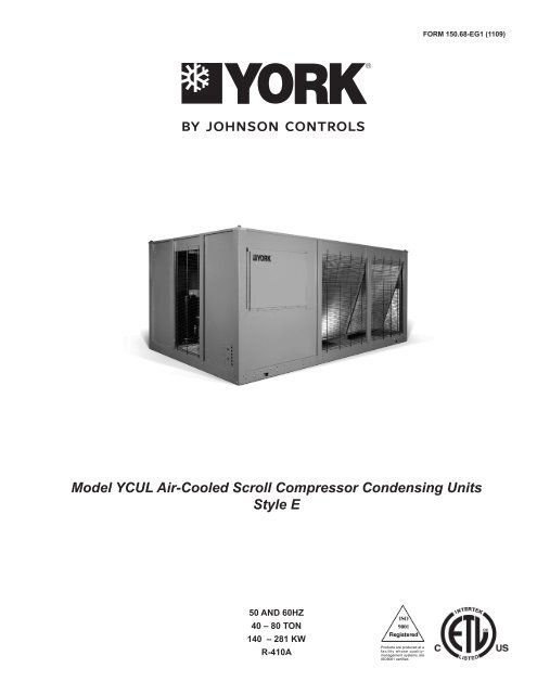
FORM 150.68-EG1 (1109)<strong>Model</strong> <strong>YCUL</strong> <strong>Air</strong>-<strong>Cooled</strong> <strong>Scroll</strong> <strong>Compressor</strong> Condensing UnitsStyle E50 and 60Hz40 – 80 TON140 – 281 kWR-410AProducts are produced at af a c i l i t y wh o s e qualitymanagementsystems areISO9001 certified.
Table of ContentsFORM 150.68-EG1 (1109)...................................................................................................................................................................................... 1Introduction........................................................................................................................................................................................................... 3Specification.......................................................................................................................................................................................................... 4MicroComputer Control Center........................................................................................................................................................................... 5Options and Accessories..................................................................................................................................................................................... 7Unit Nomenclature................................................................................................................................................................................................ 9Selection Data..................................................................................................................................................................................................... 10Ratings - R-410A (60Hz - English Units)........................................................................................................................................................... 14Ratings - R-410A (50Hz - English Units)........................................................................................................................................................... 20Ratings - R-410A (60Hz - SI Units)..................................................................................................................................................................... 26Ratings - R-410A (50Hz - SI Units)..................................................................................................................................................................... 28Physical Data - English & SI.............................................................................................................................................................................. 30Dimensions - English.......................................................................................................................................................................................... 32Dimensions - SI................................................................................................................................................................................................... 34Isolator Selections.............................................................................................................................................................................................. 36Electrical Data - 50 & 60Hz................................................................................................................................................................................. 39Electrical Notes................................................................................................................................................................................................... 41Circuit Breaker Calculations.............................................................................................................................................................................. 42Application Data.................................................................................................................................................................................................. 43Guide Specifications.......................................................................................................................................................................................... 44JOHNSON CONTROLS
IntroductionFORM 150.68-EG1 (1109)<strong>Model</strong> <strong>YCUL</strong> <strong>Air</strong>-<strong>Cooled</strong> <strong>Scroll</strong> <strong>Compressor</strong> Condensing Units Style EYORK <strong>Air</strong>-<strong>Cooled</strong> <strong>Scroll</strong> Condensing Units are the perfect refrigeration <strong>com</strong>ponents for all air conditioningapplications that use DX central station air handling. They are designed for outdoor (roof or ground level)installation. Each unit includes hermetic scroll <strong>com</strong>pressors, an air cooled condenser, and a weatherresistant microprocessor control center, all mounted on a formed steel base.JOHNSON CONTROLS
SpecificationGENERALThe 40 - 80 Ton (140 - 281 kW) <strong>YCUL</strong> models are shipped<strong>com</strong>plete from the factory ready for installation and use.The unit is pressure-tested, evacuated and given a nitrogenholding charge and includes an initial oil charge(R-410A refrigerant supplied by others). After assembly, aoperational test is performed to assure that each controldevice operates correctly.The unit structure is heavy-gauge, galvanized steel.This galvanized steel is coated with baked-on powderpaint, which, when subjected to ASTM B117 1000 hour,salt spray testing, yields a minimum ASTM 1654 ratingof “6”. Units are designed in accordance with NFPA 70(National Electric Code), ASHRAE/ANSI 15 Safety codefor mechanical refrigeration, and are cETL listed. All unitsare produced at an ISO 9000-registered facility.COMPRESSORSThe chiller has suction-gas cooled, hermetic, scroll <strong>com</strong>pressors.The <strong>YCUL</strong> <strong>com</strong>pressors incorporate a scroll designthat is <strong>com</strong>pliant in both the axial and radial direction.All rotating parts are statically and dynamically balanced.A large internal volume and oil reservoir provides greaterliquid tolerance. <strong>Compressor</strong> crankcase heaters are alsoincluded for extra protection against liquid migration.CONDENSERCoils – Fin and tube condenser coils of seamless, internally-enhanced,high-condensing-coefficient, corrosionresistant copper tubes are arranged in staggered rows,mechanically expanded into aluminum fins. Integralsubcooling is included. The design working pressure ofthe coil is 650 PSIG (45 barg).Low Sound Fans – The condenser fans are <strong>com</strong>posed ofcorrosion resistant aluminum hub and <strong>com</strong>posite bladesmolded into a low noise airfoil section. They are designedfor maximum efficiency and are statically and dynamicallybalanced for vibration-free operation. They are directlydriven, and positioned for vertical air discharge. The fanguards are constructed of heavy-gauge, rust-resistant,PVC (polyvinyl chloride)-coated steel wire.Motors – The fan motors are Totally Enclosed <strong>Air</strong>-Over,squirrel-cage type, current protected. They feature ballbearings that are double-sealed and permanently lubricated.JOHNSON CONTROLS
MicroComputer Control CenterFORM 150.68-EG1 (1109)All controls are contained in a NEMA 3R/12 cabinet withhinged outer door and includes:Liquid Crystal Display with Light Emitting Diode backlightingfor outdoor viewing:• Two display lines• Twenty characters per lineColor coded 12-button non-tactile keypad with sectionsfor:DISPLAY/PRINT of typical information:• Suction temperatures (optional)• Ambient temperature• System pressures (each circuit)• Operating hours and starts (each <strong>com</strong>pressor)• Print calls up to the liquid crystal display:• Operating data for the systems• History of fault shutdown data for up to the lastsix fault shutdown conditions• An RS-232 port, in conjunction with this press-to-printbutton, is provided to permit the capability of hardcopy print-outs via a separate printer (by others).ENTRY section to:• ENTER setpoints or modify system values SETPOINTSupdating can be performed to:• Suction pressure setting• Suction pressure control zone• Remote reset temperature range• Set daily schedule/holiday for start/stop• Manual override for servicing• Low and high ambient cutouts• Number of <strong>com</strong>pressors• Low suction pressure cutout• High discharge pressure cutout• Anti-recycle timer (<strong>com</strong>pressor start cycle time)• Anti-coincident timer (delay <strong>com</strong>pressor starts) UNITsection to:• Set clock• Set options• Set unit optionSet unit control for Discharge <strong>Air</strong> Temperature Control orfor Suction Pressure Control (requires Suction PressureTransducers – standard.UNIT ON/OFF switchThe microprocessor control center is capable of displayingthe following:• Suction temperatures (optional)• Low ambient temperature cutout setting• Outdoor air temperature• English or Metric data• Suction pressure cutout setting• Each system suction pressure• System discharge pressure• Discharge <strong>Air</strong> Temperature Reset via a YORKISN DDC or Building Automation System (by others) via:- a pulse width modulated (PWM) input as standard- a 4-20 milliamp or 0 -10 VDC input, or contact closurewith the optional B.A.S. interface option• Anti-recycle timer status for each system• Anti-coincident system start timer condition• <strong>Compressor</strong> run status• No cooling load condition• Day, date and time• Daily start/stop times• Holiday status• Automatic or manual system lead/lag control(Discharge <strong>Air</strong> Temperature control only)• Automatic lead/lag of <strong>com</strong>pressors within a system• <strong>Compressor</strong> starts & operating hours (each <strong>com</strong>pressor)• Status of hot gas valves, and fan operation• Run permissive status• Number of <strong>com</strong>pressors running• Liquid solenoid valve status• Load & unload timer statusProvisions are included for: pumpdown at shutdown;optional remote discharge air temperature reset and twosteps of demand load limiting from an external buildingautomation system. Unit alarm contacts are standard.The operating program is stored in non-volatile memory(EPROM) to eliminate chiller failure due to AC poweredfailure/battery discharge. Programmed setpoints are retainedin lithium battery-backed RTC memory for 5 yearsminimum.* Intensity of Protection European StandardJOHNSON CONTROLS
MicroComputer Control Center - continuedCOMMUNICATIONS• Native <strong>com</strong>munication capability for BACnet (MS/TP)and Modbus• Optional <strong>com</strong>munciation available for N2 and LON viaeLink optionPOWER PANELEach panel contains:• <strong>Compressor</strong> power terminals• <strong>Compressor</strong> motor starting contactors perl.E.C.*• Control power terminals to accept in<strong>com</strong>ing for 115-1-60 control power• Fan contactors & overload current protectionThe power wiring is routed through liquid-tight conduit tothe <strong>com</strong>pressors and fans.** International Electrotechnical CommissionJOHNSON CONTROLS
Options and AccessoriesFORM 150.68-EG1 (1109)ELECTRICAL OPTIONS:COMPRESSOR POWER CONNECTIONS – Single-pointterminal block connection(s) are provided as standard.The following power connections are available as options.(See electrical data for specific voltage and options availability.)(Factory-Mounted.)SINGLE-POINT SUPPLY TERMINAL BLOCK – (standardon <strong>YCUL</strong> models). Includes enclosure, terminal-blockand interconnecting wiring to the <strong>com</strong>pressors. Separateexternal protection must be supplied, by others, in thein<strong>com</strong>ing <strong>com</strong>pressor-power wiring. (Do not include thisoption if either the SinglePoint NonFused DisconnectSwitch or Single-Point Circuit Breaker options have beenincluded.)SINGLE-POINT NON-FUSED DISCONNECT SWITCH– Unit-mounted disconnect switch with external, lockablehandle (in <strong>com</strong>pliance with Article 440-14 of N.E.C.), canbe supplied to isolate the unit power voltage for servicing.Separate external fusing must be supplied, by others inthe power wiring, which must <strong>com</strong>ply with the NationalElectrical Code and/or local codes.SINGLE-POINT CIRCUIT BREAKER – A unit mountedcircuit breaker with external, lockable handle (in <strong>com</strong>pliancewith N.E.C. Article 440-14), can be supplied to isolatethe power voltage for servicing. (This option includes theSingle-Point Power connection.)CONTROL TRANSFORMER – Converts unit power voltageto 115-1-60 or 115-1-50 for 50Hz units (0.5 or 1.0KVA capacity). Factory mounting includes primary andsecondary wiring between the transformer and the controlpanel. (Factory-Mounted.)POWER FACTOR CORRECTION CAPACITORS – Willcorrect unit <strong>com</strong>pressor power factors to a 0.90-0.95.(Factory-Mounted.)CONTROL OPTIONS:AMBIENT KIT (LOW) – Units will operate to 25°F (-4°C).This accessory includes all necessary <strong>com</strong>ponents topermit chiller operation to 0°F (-18°C). (This option includesthe Discharge Pressure Transducer / ReadoutCapability option.) For proper head pressure control inapplications below 25°F (-4°C), where wind gusts mayexceed five mph, it is re<strong>com</strong>mended that Optional CondenserLouvered Enclosure Panels also be included.(Factory-Mounted.)AMBIENT KIT (HIGH) – Required if units are to operatewhen the ambient temperature is above 110°F (43°C).Includes discharge pressure transducers. (This optionincludes the Discharge Pressure Transducer / Readout-Capability option.) (Factory-Mounted.)BUILDING AUTOMATION SYSTEM INTERFACE – Thefactory addition of a Printed Circuit Board to accept a4-20 milliamp, 0-10VDC or contact closure input to resetthe leaving chiller liquid temperature from a Building AutomationSystem. (Only one of following options can beoffered on a unit at a time: BAS, Remote Control Panel orMulti-unit Sequence Control.) (Factory-Mounted.) (Thestandard unit capabilities include remote startstop, remotewater temperature reset via a PWM input signal or up totwo steps of demand (load) limiting depending on model.The standard control panel can be directly connected toa Johnson Controls Building Automated System via thestandard onboard RS485 <strong>com</strong>munication port.)LANGUAGE LCD AND KEYPAD DISPLAY – Spanish,French, and German unit LCD controls and keypad displayavailable. Standard language is English.DISCHARGE PRESSURE TRANSDUCERS AND READ-OUT CAPABILITY – The addition of pressure transducersallows models to sense and display discharge pressure.This is re<strong>com</strong>mended for brine chilling applications. (Thisoption is included with either the low or high ambient kits.)(Factory-Mounted.)Suction Pressure Transducers – Permits unitto sense and display suction pressure. This capability isstandard on <strong>YCUL</strong> models.MOTOR CURRENT MODULE – Capable of monitoring<strong>com</strong>pressor motor current. Provides extra protectionagainst <strong>com</strong>pressor reverse rotation, phase-loss andphase imbalance. Option consists of one module perelectrical system. (Factory-Mounted.)OPTIVIEW REMOTE CONTROL PANEL – Graphicalinterface panel to remotely control and monitor up to 8different units. (Refer to form 201.18-SG4 for detailedinformation)MULTI-UNIT SEQUENCING – A separate sequencingcontrol center is provided to handle sequencing control ofup to eight chillers in parallel based on mixed liquid temperature(interconnecting wiring by others). (Only one offollowing options can be offered on a unit at a time: BAS,Remote Control Panel or Multi-Unit Sequence Control.)JOHNSON CONTROLS
Options and Accessories - continued(Factory-Mounted.)COMPRESSOR AND PIPING OPTIONS:CHICAGO CODE RELIEF VALVES – Unit will be providedwith relief valves to meet Chicago code requirements.(Factory-Mounted)SERVICE ISOLATION VALVE – Service isolation valvesare standard to unit. This includes a system high pressurerelief valve or internal <strong>com</strong>pressor relief mechanism in<strong>com</strong>pliance with ASHRAE 15. (Factory-Mounted)HOT GAS BY-PASS – Permits continuous, stable operationat capacities below the minimum step of <strong>com</strong>pressorunloading to as low as 5% capacity (depending on boththe unit and operating conditions) by introducing an artificialload on the cooler. Hot gas by-pass is installed ononly refrigerant system #1 on two-circuited units. (Factory-Mounted)CONDENSER AND CABINET OPTIONS:Condenser coil protection against corrosive environmentsis available by choosing any of the following options. Foradditional application re<strong>com</strong>mendations, refer to Form150.12-ES1. (Factory-Mounted.)PRE-COATED FIN CONDENSER COILS – The unit'scoils are constructed with epoxy coated aluminum fins.This can provide corrosion resistance <strong>com</strong>parable to copper-fincoils in typical seashore locations. Either these orthe post-coated coils (below), are re<strong>com</strong>mended for unitsbeing installed at the seashore or where salt spray mayhit the unit.POST-COATED DIPPED CONDENSER COILS – Theunit's coils are constructed with dipped-cured condensercoils. This is the choice for corrosive applications (with theexception of strong alkalies, oxidizers and wet bromine,chlorine and fluorine in concentrations greater than 100ppm).COPPER FIN CONDENSER COILS – The unit's coilsare constructed with copper fins. (This is not re<strong>com</strong>mendedfor units in areas where they may be exposedto acid rain.)ENCLOSURE PANELS (UNIT) – Tamperproof enclosurepanels prevent unauthorized access to units. Enclosurepanels can provide an aesthetically pleasing alternative toexpensive fencing. Additionally, for proper head pressurecontrol, Johnson Controls re<strong>com</strong>mends the use of :LOUVERED PANELS (Full Unit) – Louvered panelssurround the front, back, and sides of the unit. Theyprevent unauthorized access and visually screen unit<strong>com</strong>ponents. Unrestricted air flow is permitted throughgenerously sized louvered openings. This option is applicablefor any outdoor design ambient temperature upto 115°F (46°C). (Factory-Mounted.)SOUND ATTENUATION – One or both of the followingsound attenuation options are re<strong>com</strong>mended for residentialor other similar sound-sensitive locations. LouveredPanels can be ordered for winter applications where windgusts may exceed five miles per hour. The following typesof enclosure options are available:COMPRESSOR ACOUSTIC SOUND BLANKET – Each<strong>com</strong>pressor is individually enclosed by an acoustic soundblanket. The sound blankets are made with one layer ofacoustical absorbent textile fiber of 5/8” (15mm) thickness;one layer of anti-vibrating heavy material thickness of 1/8”(3mm). Both are closed by two sheets of welded PVC,reinforced for temperature and UV resistance. (Factory-Mounted.)ULTRA QUIET FANS – Lower RPM, 8-pole fan motors areused with steeper-pitch fans. (Factory-Mounted.)VIBRATION ISOLATORS – Level adjusting, spring type 1”(25.4mm) or seismic deflection or neoprene pad isolatorsJOHNSON CONTROLS
Unit NomenclatureFORM 150.68-EG1 (1109)YC U L 0045 E E 46 X EDesign SeriesYC=York CondensingUnit<strong>Compressor</strong> TypeL=<strong>Scroll</strong>Type StartX=Across-th-LineVoltage Code17=200-3-6028=230-3-6040=380-3-6046=460-3-6058=575-3-6050=380-415-3-50Nominal CapacityRefrigerantE=R-410AE= High Efficiency UnitJOHNSON CONTROLS
Selection DataThe ratings shown on pages 14 through 25 are basedon unit operation in a well designed and properly pipedsystem.SELECTION RULES1. Capabilities are based on Refrigerant R-410A.2. Ratings may interpolated, but must not be extrapolated.3. Ratings shown are at saturated suction temperaturescorresponding to pressures at the <strong>com</strong>pressor. Inactual practice, suction line pressure drop has theeffect of reducing <strong>com</strong>pressor capacity, forcing the<strong>com</strong>pressor to operate at a lower suction pressureto maintain the desired evaporator temperature.For normal air conditioning applications, size the suctionline for a pressure drop of 3 PSI (0.2 bar), corresponding to2°F (1.1°C), for R-410A refrigerant. Thus, the evaporatortemperature will be approximately 2°F (1.1°C) higher thanthe <strong>com</strong>pressor suction temperature. Line loss must betaken into consideration when selecting the evaporator.SELECTION PROCEDUREThe air-cooled condensing unit may be selected fromthe Ratings on pages 14 through 25, if the ambient airtemperature at the condenser and the saturated suctiontemperature at the <strong>com</strong>pressor are known. The ambientair temperature is a known design parameter, but thesuction temperature at the <strong>com</strong>pressor, in many cases,is known only within certain allowable limits. The actual<strong>com</strong>pressor operating suction temperature and the overallperformance of the system will depend directly uponthe choice of the evaporator. Starting with a preliminaryevaporator selection at a nominal evaporator temperatureand using data supplied by the evaporator manufacturer,enter the ratings tables and select a unit to meet therequired cooling load at a suction temperature at least2°F (1.1°C) below the evaporator temperature. The 2°F(1.1°C) allows for normal suction line loss.If more accurate selection is required, the evaporatorcapacity should be plotted against the condensing unitcapacity to determine the balanced system performance.Again, it is necessary to factor in the suction line loss.After the system balance point has been determined,the <strong>com</strong>pressor KW input may be interpolated from theratings tables.SAMPLE SELECTIONSelect an R-410A <strong>Air</strong>-<strong>Cooled</strong> Condensing Unit with amatched central station air handling unit having the followingoperating conditions:Design Conditions1. An air handling unit with two large DX coils (one percircuit) having a total cooling load of 600 MBH (50tons).2. The coil suction temperature required 45°F.3. The design outdoor ambient temperature is 95°F.4. The power supply is 460V/3∅/60 hz.Selection1. Enter the <strong>YCUL</strong>0055EE Rating Table (page 12).2. The model <strong>YCUL</strong>0055EE will provide 51.6 tons with48.9 <strong>com</strong>pressor KW input at 95°F ambient air and45°F suction pressure.3. Calculate the <strong>com</strong>pressor Kw input for the specificdesign conditions of 50 tons and 95°F ambient air.KW =5051.6 Kwx 48.9 Kw = 47.4 KwThe <strong>YCUL</strong>0055EE is the suitable selection for the designcapacity.10JOHNSON CONTROLS
Selection Data - continuedFORM 150.68-EG1 (1109)Refrigerant PIPINGGeneral – When the unit has been located in its finalposition, the unit piping may be connected. Normal installationprecautions should be observed in order to receivemaximum operating efficiencies. System piping shouldconform to the York DX piping guide form 050.40-ES2 orASHRAE refrigeration handbook guidelines. All pipingdesign and installation is the responsibility of the user.JOHNSON CONTROLS ASSUMES NO WARRANTYRESPONSIBILITY FOR SYSTEM OPERATION ORFAILURES DUE TO IMPROPER PIPING OR PIPINGDESIGN.Filter driers and sight glasses are shipped loose for fieldinstallation on each refrigerant circuit. Field refrigerantpiping can be connected to the condensing unit.All expansion valves, liquid line solenoid valves, refrigerantand refrigerant piping are supplied and installed byothers.Table 4, pg 13, lists refrigerant line connections sizes perunit model number.REFRIGERANT LINE SIZINGRefrigerant piping systems must be designed to providepractical line sizes without excessive pressure drops,prevent <strong>com</strong>pressor oil from being “trapped” in the refrigerantpiping, and ensure proper flow of liquid refrigerantto the thermal expansion valve. Considerations shouldbe given to:1) Suction line pressure drop due to refrigerant flow.2) Suction line refrigerant velocity for oil return.3) Liquid line pressure drop due to refrigerant flow.4) Liquid line pressure drop (or gain) due to vertical riseof the liquid line.Table 5 provides the pressure drops for given pipe sizes forboth liquid and suction lines. The pressure drops given areper 100 equivalent ft. (30.5 m) of refrigerant piping. Thesefriction losses do not include any allowances for strainer,filter drier, solenoid valve, isolation valve or fittingsNominal pressure drop for solenoids, sight glass, anddriers are shown in Table 2, pg 12.Table 1, pg 12, includes approximate equivalent l<strong>eng</strong>thsfor copper fittings.To ensure a solid column of liquid refrigerant to the expansionvalve, the total liquid line pressure drop should neverexceed 50 psi (3.4 bar). Refrigerant vapor in the liquid linewill measurably reduce valve capacity and poor systemperformance can be expected.To allow adequate oil return to the <strong>com</strong>pressor, suctionrisers should be sized for a minimum of 1000 FPM (5.08m/s) while the system is operating at minimum capacityto ensure oil return up the suction riser.Evaporator Below Condensing UnitOn a system where the evaporator is located below thecondensing unit, the suction line must be sized for bothpressure drop and oil return. In some cases a double suctionriser must be installed to ensure reliable oil return atreduced loads. Table 3, pg 12, indicates when a doublesuction riser should be used for listed pipe sizes to provideadequate oil return at reduced loads. The calculatedinformation was based on maintaining a minimum of 1000fpm (5.08 m/s) refrigerant vapor velocity.Condenser Below EvaporatorWhen the condensing unit is located below the evaporator,the liquid line must be designed for both friction loss andstatic head loss due the vertical rise. The value of statichead loss of 5 PSI/ft (3.4 kPa/30 cm) must be added tothe friction loss pressure drop in addition to all pressuredrops due to driers, valves, etc.OIL TRAPSAll horizontal suction lines should be pitched at least 1/4"per foot (2 cm/m) in the direction of the refrigerant flow toaid in the return of oil to the <strong>com</strong>pressor. All suction lineswith a vertical rise exceeding 3 feet (.91 meters) shouldhave a “P” trap at the bottom and top of the riser. Suctionlines with a vertical rise exceeding 25 feet (7.6 meters)should be trapped every 15 feet (4.6 meters).REFRIGERANT CHARGEThe condensing unit is charged with a dry nitrogen holdingcharge. The remaining operating charge for the condensingunit, evaporator coil, and refrigerant piping must beweighed in after all refrigerant piping is installed, leakchecked, and evacuated. Final adjustment of refrigerantcharge should be verified by subcooling values (refer tosection on Pre-Startup for checking subcooling).REFRIGERANT PIPING REFERENCEFor more details, refer to ASHRAE Refrigeration Handbook,Chapter 2.JOHNSON CONTROLS 11
Selection Data - continuedTABLE 1 - FITTING EQUIVALENT LENGTHS<strong>YCUL</strong> Short Radius Ell Long Radius Ell3/4" (19mm) 6.5ft. (2m) 4.5 ft.(1.4m)7/8" (22mm) 7.8 ft. (2.4m) 5.3 ft (1.6m)1-1/8" (29mm)2.7ft. (.8m)1.9 ft. (.6m)1-3/8" (35mm) 3.2 ft. (1m)2.2 ft. (.7m)1-5/8" (41mm) 3.8 ft. (1.2m) 2.6 ft. (.8m)2-1/8" (54mm) 5.2 ft. (1.6m) 3.4 ft. (1m)2-5/8" (67mm) 6.5 ft (20m) 4.2 ft. (1.3m)*Copper Fitting Equivalent L<strong>eng</strong>thsTABLE 2 – MISCELLANEOUS LIQUID LINE PRESSURE DROPSSolenoid Valve2-3 PSI (13.8 - 20.7kPa)Filter/Drier2-3 PSI (13.8 - 20.7kPa)Sight Glass0.5PSI (3.4 kPa)TABLE 3 – REFRIGERATION PIPING CHARGESR-410a Suct @ 36 deg Liq @ 105 degSUCTION LINESSize ID Cu ftDensity Lb/CuFtOz./Ft. Grams/30 Cm1-3/8 1.3 0.0 2.1 0.3 8.11-5/8 1.5 0.0 2.1 0.4 11.52-1/8 2.0 0.0 2.1 0.7 20.02-5/8 2.5 0.0 2.1 1.1 30.9LIQUID LINES3/4 0.7 0.0 60.9 2.4 66.87/8 0.8 0.0 60.9 3.3 92.81-1/8 1.0 0.0 60.9 5.6 158.31-3/8 1.3 0.0 60.9 8.5 241.112JOHNSON CONTROLS
FORM 150.68-EG1 (1109)TABLE 4 – REFRIGERANT LINE CONNECTIONSMODELNUMBERTONSSYSTEMNUMBERREFRIGERANT LINECONNECTIONSUCTIONLIQUIDSUCTION LINECOPPER TYPEL INCHES ODNOMINALTONSUNLOADEDLIQUID LINECOPPERTYPE LINCHES OD0045EE 41.60051EE 44.10055EE 51.60065EE 59.50072EE 73.51 2.1 1.1 2-1/8 10.4 1-1/82 2.1 1.1 2-1/8 10.4 1-1/81 2.1 1.1 2-1/8 11.7 1-1/82 2.1 1.1 2-1/8 10.4 1-1/81 2.1 1.1 2-1/8 12.9 1-1/82 2.1 1.1 2-1/8 12.9 1-1/81 2.1 1.1 2-1/8 14.9 1-1/82 2.1 1.1 2-1/8 14.9 1-1/81 2.3 1.1 2-3/8 21.9 1-1/82 2.1 1.1 2-1/8 14.9 1-1/8Refrigerant Piping Notes1. Based on R-410A at the nominal capacity of the unit or system, an ambient temperature of 95°F (35°C) and a suction temperature of 45°F(7.2°C).2. Suction line sizes were calculated based on a nominal maximum pressure drop to 3 PSI/100 ft. (20.7 kPa/30.5 m). When calculating suction linepressure drop for a specific application, it should be noted that system capacity decreases as suction line pressure drop increases.4. Nominal Tons (KW) Unloaded is based on one <strong>com</strong>pressor (per system) operating at design conditions.5. Based on minimum <strong>com</strong>pressor staging for the given pipe size, a double suction riser should be used to ensure proper oil return to the <strong>com</strong>pressoron all vertical suction risers. Oil returning up the riser moves up the inner surface of the pipe and depends on the mass velocity of therefrigerant vapor at the wall surface to move the oil up the vertical rise.6. Hot gas bypass lines are typically 7/8” for lines up to 40 feet and 1-1/8” for lines over 40 feet in l<strong>eng</strong>th (12 meters). The field connections sizesare 7/8” for the optional factory mounted hot gas bypass valve. Note: Hot gas bypass is only available for refrigerant system number 1.7. For more information, please refer to either the York DX Piping Guide (Form 050.40-ES2) or the ASHRAE Refrigertion Handbook.JOHNSON CONTROLS 13
Ratings - R-410A (60Hz - English Units)MODEL: <strong>YCUL</strong>0045EEAIR TEMPERATURE ON - CONDENSER (°F)SST (°F)75.0 80.0 85.0 90.0 95.0TONS KW EER TONS KW EER TONS KW EER TONS KW EER TONS KW EER35.0 39.4 30.8 13.0 38.3 32.4 12.1 37.1 34.2 11.2 35.9 36.2 10.3 34.7 38.4 9.437.0 40.8 31.0 13.4 39.7 32.6 12.5 38.5 34.4 11.6 37.3 36.4 10.7 36.0 38.6 9.839.0 42.2 31.2 13.8 41.1 32.8 12.8 39.9 34.6 11.9 38.7 36.6 11.0 37.3 38.8 10.141.0 43.6 31.4 14.1 42.5 33.0 13.2 41.3 34.8 12.3 40.1 36.8 11.3 38.7 39.1 10.443.0 45.1 31.6 14.5 44.0 33.2 13.6 42.8 35.0 12.6 41.5 37.1 11.7 40.1 39.3 10.745.0 46.6 31.8 14.9 45.5 33.4 14.0 44.2 35.3 13.0 42.9 37.3 12.0 41.6 39.5 11.147.0 48.1 32.0 15.3 47.0 33.7 14.4 45.7 35.5 13.4 44.4 37.6 12.4 43.0 39.8 11.449.0 49.7 32.2 15.8 48.5 33.9 14.7 47.3 35.8 13.7 45.9 37.8 12.7 44.5 40.0 11.751.0 51.2 32.4 16.2 50.1 34.1 15.1 48.8 36.0 14.1 47.5 38.1 13.0 46.0 40.3 12.053.0 52.9 32.7 16.6 51.7 34.4 15.5 50.4 36.3 14.4 49.0 38.3 13.4 47.5 40.6 12.355.0 54.5 32.9 17.0 53.3 34.6 15.9 52.0 36.5 14.8 50.6 38.6 13.7 49.1 40.9 12.7MODEL: <strong>YCUL</strong>0051EEAIR TEMPERATURE ON - CONDENSER (°F)SST (°F)75.0 80.0 85.0 90.0 95.0TONS KW EER TONS KW EER TONS KW EER TONS KW EER TONS KW EER35.0 42.0 33.7 12.8 40.8 35.5 11.9 39.5 37.5 11.0 38.2 39.7 10.1 36.9 42.1 9.337.0 43.5 34.0 13.2 42.2 35.8 12.2 41.0 37.8 11.3 39.6 39.9 10.4 38.3 42.3 9.639.0 45.0 34.2 13.6 43.7 36.0 12.6 42.4 38.0 11.7 41.1 40.2 10.8 39.7 42.6 9.941.0 46.6 34.5 13.9 45.3 36.3 13.0 43.9 38.3 12.0 42.6 40.5 11.1 41.1 42.9 10.243.0 48.2 34.8 14.3 46.8 36.6 13.3 45.5 38.6 12.4 44.1 40.8 11.4 42.6 43.1 10.545.0 49.8 35.0 14.7 48.4 36.9 13.7 47.1 38.9 12.7 45.6 41.1 11.7 44.1 43.4 10.847.0 51.4 35.3 15.1 50.1 37.2 14.0 48.7 39.2 13.0 47.2 41.4 12.1 45.6 43.7 11.149.0 53.1 35.6 15.5 51.7 37.5 14.4 50.3 39.5 13.4 48.8 41.7 12.4 47.2 44.1 11.451.0 54.9 35.9 15.8 53.4 37.8 14.8 51.9 39.8 13.7 50.4 42.0 12.7 48.8 44.4 11.753.0 56.6 36.2 16.2 55.2 38.1 15.1 53.6 40.2 14.1 52.0 42.4 13.0 50.4 44.7 12.055.0 58.4 36.6 16.6 56.9 38.4 15.5 55.4 40.5 14.4 53.7 42.7 13.3 52.1 45.1 12.3# indicates package unloaded due to high pressure conditions? indicates no rating available at this condition14JOHNSON CONTROLS
FORM 150.68-EG1 (1109)MODEL: <strong>YCUL</strong>0045EEAIR TEMPERATURE ON - CONDENSER (°F)SST (°F)100.0 105.0 110.0 115.0TONS KW EER TONS KW EER TONS KW EER TONS KW EER35.0 33.3 40.9 8.6 31.9 43.6 7.8 30.5 46.5 7.0 29.1 49.6 6.337.0 34.6 41.1 8.9 33.2 43.7 8.1 31.8 46.6 7.3 30.3 49.7 6.639.0 36.0 41.3 9.2 34.5 43.9 8.4 33.0 46.8 7.6 31.5 49.9 6.841.0 37.3 41.5 9.5 35.8 44.1 8.6 34.3 47.0 7.8 32.8 50.1 7.143.0 38.7 41.7 9.8 37.2 44.4 8.9 35.6 47.2 8.1 34.0 50.2 7.345.0 40.1 42.0 10.1 38.6 44.6 9.2 37.0 47.4 8.4 35.3 50.5 7.647.0 41.5 42.2 10.4 40.0 44.8 9.5 38.4 47.7 8.6 36.7 50.7 7.849.0 43.0 42.5 10.7 41.4 45.1 9.8 39.7 47.9 8.9 38.0 50.9 8.151.0 44.5 42.8 11.0 42.8 45.4 10.1 41.2 48.2 9.2 39.4 51.2 8.353.0 46.0 43.1 11.3 44.3 45.7 10.4 42.6 48.5 9.5 40.8 51.5 8.655.0 47.5 43.4 11.6 45.8 46.0 10.7 44.1 48.8 9.7 42.2 51.8 8.8MODEL: <strong>YCUL</strong>0051EEAIR TEMPERATURE ON - CONDENSER (°F)SST (°F)100.0 105.0 110.0 115.0TONS KW EER TONS KW EER TONS KW EER TONS KW EER35.0 35.5 44.7 8.5 34.0 47.5 7.7 32.6 50.5 7.0 31.0 53.7 6.337.0 36.8 44.9 8.8 35.4 47.7 8.0 33.9 50.7 7.2 32.3 53.9 6.539.0 38.2 45.2 9.0 36.7 47.9 8.2 35.2 50.9 7.5 33.6 54.1 6.741.0 39.6 45.4 9.3 38.1 48.2 8.5 36.5 51.1 7.7 34.9 54.3 7.043.0 41.1 45.7 9.6 39.5 48.5 8.8 37.9 51.4 8.0 36.2 54.6 7.245.0 42.5 46.0 9.9 40.9 48.7 9.0 39.3 51.7 8.2 37.6 54.8 7.547.0 44.0 46.3 10.2 42.4 49.1 9.3 40.7 52.0 8.5 39.0 55.1 7.749.0 45.6 46.6 10.5 43.9 49.4 9.6 42.2 52.3 8.7 40.4 55.4 7.951.0 47.1 47.0 10.8 45.4 49.7 9.9 43.6 52.6 9.0 41.8 55.8 8.253.0 48.7 47.3 11.0 46.9 50.0 10.1 45.1 53.0 9.2 43.3 56.1 8.455.0 50.3 47.7 11.3 48.5 50.4 10.4 46.7 53.3 9.5 44.7 56.4 8.7# indicates package unloaded due to high pressure conditions? indicates no rating available at this conditionJOHNSON CONTROLS 15
Ratings - R-410A (60Hz - English Units) - Cont.MODEL: <strong>YCUL</strong>0055EEAIR TEMPERATURE ON - CONDENSER (°F)SST (°F)75.0 80.0 85.0 90.0 95.0TONS KW EER TONS KW EER TONS KW EER TONS KW EER TONS KW EER35.0 48.8 38.1 13.1 47.5 40.1 12.2 46.1 42.3 11.3 44.7 44.6 10.5 43.3 47.1 9.737.0 50.6 38.4 13.4 49.2 40.5 12.5 47.8 42.6 11.6 46.3 44.9 10.8 44.9 47.4 9.939.0 52.5 38.8 13.8 51.0 40.8 12.9 49.5 43.0 12.0 48.0 45.3 11.1 46.5 47.8 10.241.0 54.4 39.2 14.2 52.8 41.2 13.2 51.3 43.4 12.3 49.7 45.7 11.4 48.2 48.1 10.543.0 56.3 39.6 14.6 54.7 41.6 13.6 53.1 43.8 12.6 51.5 46.1 11.7 49.9 48.5 10.845.0 58.3 40.0 15.0 56.6 42.0 13.9 55.0 44.2 13.0 53.3 46.5 12.0 51.6 48.9 11.147.0 60.3 40.5 15.3 58.6 42.5 14.3 56.9 44.6 13.3 55.1 46.9 12.3 53.4 49.3 11.449.0 62.4 41.0 15.7 60.6 42.9 14.7 58.8 45.0 13.6 57.0 47.3 12.7 55.2 49.8 11.751.0 64.5 41.4 16.1 62.7 43.4 15.0 60.8 45.5 14.0 59.0 47.8 13.0 57.1 50.2 12.053.0 66.7 41.9 16.5 64.8 43.9 15.4 62.9 46.0 14.3 60.9 48.3 13.3 59.0 50.7 12.355.0 68.9 42.5 16.8 67.0 44.4 15.7 65.0 46.5 14.7 63.0 48.8 13.6 60.9 51.2 12.6MODEL: <strong>YCUL</strong>0065EEAIR TEMPERATURE ON - CONDENSER (°F)SST (°F)75.0 80.0 85.0 90.0 95.0TONS KW EER TONS KW EER TONS KW EER TONS KW EER TONS KW EER35.0 56.5 46.4 12.8 55.0 48.7 11.9 53.4 51.2 11.1 51.8 53.8 10.3 50.1 56.7 9.537.0 58.5 46.9 13.1 57.0 49.2 12.2 55.4 51.6 11.4 53.7 54.3 10.6 51.9 57.2 9.739.0 60.6 47.4 13.4 59.0 49.7 12.5 57.3 52.2 11.7 55.6 54.8 10.8 53.7 57.7 10.041.0 62.7 48.0 13.7 61.0 50.2 12.9 59.3 52.7 12.0 57.5 55.4 11.1 55.6 58.2 10.343.0 64.8 48.6 14.1 63.1 50.8 13.2 61.3 53.3 12.3 59.5 55.9 11.4 57.5 58.8 10.545.0 66.9 49.2 14.4 65.2 51.4 13.5 63.4 53.9 12.5 61.5 56.5 11.7 59.5 59.4 10.847.0 69.1 49.8 14.7 67.3 52.1 13.7 65.5 54.5 12.8 63.5 57.2 11.9 61.5 60.0 11.149.0 71.4 50.5 15.0 69.5 52.8 14.0 67.6 55.2 13.1 65.6 57.8 12.2 63.5 60.7 11.351.0 73.6 51.2 15.2 71.7 53.5 14.3 69.7 55.9 13.4 67.7 58.5 12.4 65.5 61.3 11.653.0 75.9 52.0 15.5 74.0 54.2 14.6 71.9 56.6 13.6 69.8 59.2 12.7 67.6 62.1 11.855.0 78.3 52.8 15.8 76.3 55.0 14.8 74.2 57.4 13.9 72.0 60.0 12.9 69.7 62.8 12.0# indicates package unloaded due to high pressure conditions? indicates no rating available at this condition16JOHNSON CONTROLS
FORM 150.68-EG1 (1109)MODEL: <strong>YCUL</strong>0055EEAIR TEMPERATURE ON - CONDENSER (°F)SST (°F)100.0 105.0 110.0 115.0TONS KW EER TONS KW EER TONS KW EER TONS KW EER35.0 41.8 49.7 8.9 40.3 52.5 8.2 38.8 55.5 7.5 37.1 58.7 6.837.0 43.4 50.1 9.2 41.8 52.9 8.4 40.2 55.9 7.7 38.5 59.0 7.039.0 44.9 50.4 9.4 43.3 53.2 8.7 41.7 56.2 7.9 39.9 59.4 7.241.0 46.5 50.8 9.7 44.9 53.6 8.9 43.2 56.6 8.2 41.4 59.8 7.543.0 48.2 51.2 10.0 46.5 54.0 9.2 44.7 57.0 8.4 42.8 60.1 7.745.0 49.9 51.6 10.3 48.1 54.4 9.4 46.2 57.4 8.7 44.3 60.5 7.947.0 51.6 52.0 10.5 49.7 54.8 9.7 47.8 57.8 8.9 45.9 60.9 8.149.0 53.3 52.4 10.8 51.4 55.2 10.0 49.5 58.2 9.1 47.4 61.4 8.451.0 55.1 52.9 11.1 53.2 55.6 10.2 51.1 58.6 9.4 49.1 61.8 8.653.0 57.0 53.3 11.4 54.9 56.1 10.5 52.8 59.1 9.6 50.7 62.3 8.855.0 58.8 53.8 11.7 56.7 56.6 10.8 54.6 59.6 9.9 52.4 62.7 9.0MODEL: <strong>YCUL</strong>0065EEAIR TEMPERATURE ON - CONDENSER (°F)SST (°F)100.0 105.0 110.0 115.0TONS KW EER TONS KW EER TONS KW EER TONS KW EER35.0 48.3 59.8 8.7 46.5 63.1 8.0 44.6 66.6 7.3 42.6 70.3 6.637.0 50.1 60.3 9.0 48.2 63.6 8.2 46.2 67.1 7.5 44.2 70.8 6.839.0 51.9 60.8 9.2 49.9 64.1 8.5 47.9 67.6 7.7 45.9 71.3 7.141.0 53.7 61.3 9.5 51.7 64.6 8.7 49.6 68.1 8.0 47.5 71.8 7.343.0 55.6 61.8 9.7 53.5 65.1 8.9 51.4 68.6 8.2 49.2 72.3 7.545.0 57.4 62.4 10.0 55.3 65.7 9.2 53.1 69.2 8.4 50.9 72.9 7.747.0 59.4 63.0 10.2 57.2 66.3 9.4 54.9 69.8 8.6 52.6 73.5 7.949.0 61.3 63.7 10.4 59.1 66.9 9.6 56.8 70.4 8.8 54.4 74.1 8.151.0 63.3 64.4 10.7 61.0 67.6 9.9 58.6 71.1 9.0 56.2 74.8 8.353.0 65.3 65.1 10.9 63.0 68.3 10.1 60.5 71.8 9.3 58.0 75.4 8.555.0 67.4 65.8 11.1 64.9 69.0 10.3 62.5 72.5 9.5 59.9 76.2 8.7# indicates package unloaded due to high pressure conditions? indicates no rating available at this conditionJOHNSON CONTROLS 17
Ratings - R-410A (60Hz - English Units) - Cont.MODEL: <strong>YCUL</strong>0072EEAIR TEMPERATURE ON - CONDENSER (°F)SST (°F)75.0 80.0 85.0 90.0 95.0TONS KW EER TONS KW EER TONS KW EER TONS KW EER TONS KW EER35.0 69.9 58.2 12.9 67.9 61.1 12.0 65.8 64.2 11.1 63.7 67.7 10.3 61.6 71.4 9.537.0 72.5 58.9 13.2 70.4 61.8 12.3 68.2 64.9 11.4 66.1 68.3 10.6 63.9 72.1 9.739.0 75.1 59.6 13.6 72.9 62.5 12.6 70.7 65.6 11.7 68.5 69.0 10.8 66.2 72.8 10.041.0 77.7 60.4 13.9 75.5 63.2 12.9 73.2 66.4 12.0 70.9 69.8 11.1 68.6 73.5 10.343.0 80.4 61.1 14.2 78.1 64.0 13.3 75.8 67.1 12.3 73.4 70.6 11.4 71.0 74.3 10.545.0 83.2 61.9 14.5 80.8 64.8 13.6 78.4 67.9 12.6 75.9 71.4 11.7 73.5 75.1 10.847.0 86.0 62.7 14.9 83.5 65.6 13.9 81.0 68.8 12.9 78.5 72.2 11.9 76.0 75.9 11.049.0 88.9 63.5 15.2 86.3 66.4 14.2 83.8 69.6 13.2 81.2 73.1 12.2 78.6 76.8 11.351.0 91.8 64.4 15.5 89.2 67.3 14.5 86.5 70.5 13.4 83.9 73.9 12.5 81.2 77.7 11.553.0 94.8 65.3 15.8 92.1 68.2 14.7 89.4 71.4 13.7 86.6 74.9 12.7 83.9 78.6 11.855.0 97.8 66.2 16.1 95.1 69.2 15.0 92.2 72.4 14.0 89.4 75.8 13.0 86.6 79.6 12.0# indicates package unloaded due to high pressure conditions? indicates no rating available at this condition18JOHNSON CONTROLS
FORM 150.68-EG1 (1109)MODEL: <strong>YCUL</strong>0072EEAIR TEMPERATURE ON - CONDENSER (°F)SST (°F)100.0 105.0 110.0 115.0TONS KW EER TONS KW EER TONS KW EER TONS KW EER35.0 59.5 75.4 8.7 57.3 79.8 7.9 55.1 84.5 7.3 52.9 89.5 6.637.0 61.7 76.1 8.9 59.4 80.4 8.2 57.2 85.1 7.5 54.9 90.2 6.839.0 63.9 76.8 9.2 61.6 81.1 8.4 59.3 85.8 7.7 56.9 90.9 7.041.0 66.2 77.5 9.4 63.8 81.9 8.6 61.4 86.5 7.9 59.0 91.6 7.243.0 68.6 78.3 9.7 66.1 82.6 8.9 63.6 87.3 8.1 45.4 62.0 7.9#45.0 71.0 79.1 9.9 68.4 83.4 9.1 65.9 88.1 8.3 47.1 62.4 8.2#47.0 73.4 79.9 10.2 70.8 84.2 9.3 68.2 88.9 8.6 48.8 62.9 8.4#49.0 75.9 80.8 10.4 73.2 85.1 9.6 70.5 89.8 8.8 50.5 63.4 8.7#51.0 78.5 81.7 10.7 75.7 86.0 9.8 72.9 90.7 9.0 52.3 63.8 8.9#53.0 81.1 82.6 10.9 78.2 86.9 10.0 75.4 91.6 9.2 38.8 41.8 9.6@55.0 83.7 83.6 11.1 80.8 87.9 10.2 77.9 92.6 9.4 40.2 42.1 9.9@# indicates package unloaded due to high pressure conditions? indicates no rating available at this conditionJOHNSON CONTROLS 19
Ratings - R-410A (50Hz - English Units)MODEL: <strong>YCUL</strong>0045EEAIR TEMPERATURE ON - CONDENSER (F)SST (F)75.0 80.0 85.0 90.0 95.0TONS KW EER TONS KW EER TONS KW EER TONS KW EER TONS KW EER35.0 32.6 24.3 14.2 31.7 25.9 13.1 30.8 27.6 12.0 29.8 29.4 10.9 28.7 31.4 9.937.0 33.8 24.5 14.6 32.9 26.1 13.5 31.9 27.7 12.4 30.9 29.5 11.3 29.8 31.5 10.339.0 35.0 24.7 15.1 34.1 26.2 13.9 33.1 27.9 12.8 32.0 29.7 11.7 30.9 31.6 10.641.0 36.2 24.8 15.5 35.3 26.4 14.3 34.3 28.0 13.1 33.2 29.8 12.0 32.1 31.8 11.043.0 37.5 25.0 15.9 36.5 26.6 14.7 35.5 28.2 13.5 34.4 30.0 12.4 33.3 31.9 11.345.0 38.8 25.2 16.3 37.8 26.8 15.1 36.7 28.4 13.9 35.6 30.2 12.8 34.4 32.1 11.747.0 40.1 25.5 16.8 39.1 27.0 15.5 38.0 28.6 14.3 36.9 30.4 13.2 35.7 32.3 12.049.0 41.4 25.7 17.2 40.4 27.2 15.9 39.3 28.8 14.7 38.1 30.6 13.5 36.9 32.5 12.451.0 42.8 25.9 17.6 41.7 27.4 16.3 40.6 29.0 15.1 39.4 30.8 13.9 38.2 32.7 12.853.0 44.2 26.2 18.0 43.1 27.7 16.7 41.9 29.3 15.5 40.7 31.0 14.3 39.5 32.9 13.155.0 45.6 26.5 18.4 44.5 28.0 17.1 43.3 29.5 15.9 42.1 31.3 14.6 40.8 33.1 13.5MODEL: <strong>YCUL</strong>0051EEAIR TEMPERATURE ON - CONDENSER (F)SST (F)75.0 80.0 85.0 90.0 95.0TONS KW EER TONS KW EER TONS KW EER TONS KW EER TONS KW EER35.0 34.8 26.8 13.9 33.8 28.4 12.8 32.7 30.2 11.7 31.7 32.2 10.7 30.6 34.3 9.837.0 36.0 26.9 14.3 35.0 28.6 13.2 33.9 30.4 12.1 32.9 32.3 11.1 31.7 34.4 10.139.0 37.3 27.1 14.7 36.3 28.8 13.6 35.2 30.6 12.5 34.1 32.5 11.4 32.9 34.6 10.441.0 38.7 27.3 15.2 37.6 29.0 14.0 36.5 30.8 12.9 35.3 32.7 11.8 34.1 34.8 10.843.0 40.0 27.5 15.6 38.9 29.2 14.4 37.8 31.0 13.2 36.6 32.9 12.1 35.3 35.0 11.145.0 41.4 27.8 16.0 40.3 29.4 14.8 39.1 31.2 13.6 37.9 33.1 12.5 36.6 35.2 11.447.0 42.8 28.0 16.4 41.7 29.7 15.2 40.4 31.4 14.0 39.2 33.3 12.9 37.9 35.4 11.849.0 44.3 28.3 16.9 43.1 29.9 15.6 41.8 31.7 14.4 40.5 33.6 13.2 39.2 35.6 12.151.0 45.8 28.5 17.3 44.5 30.2 16.0 43.2 31.9 14.8 41.9 33.8 13.6 40.6 35.9 12.453.0 47.3 28.8 17.7 46.0 30.4 16.4 44.7 32.2 15.1 43.3 34.1 13.9 41.9 36.1 12.855.0 48.8 29.1 18.1 47.5 30.7 16.8 46.2 32.5 15.5 44.8 34.4 14.3 43.3 36.4 13.1# indicates package unloaded due to high pressure conditions? indicates no rating available at this condition20JOHNSON CONTROLS
FORM 150.68-EG1 (1109)MODEL: <strong>YCUL</strong>0045EEAIR TEMPERATURE ON - CONDENSER (F)SST (F)100.0 105.0 110.0 115.0TONS KW EER TONS KW EER TONS KW EER TONS KW EER35.0 27.6 33.5 9.0 26.5 35.8 8.1 25.3 38.3 7.3 24.0 41.0 6.537.0 28.7 33.6 9.3 27.5 35.9 8.4 26.3 38.4 7.6 25.0 41.0 6.839.0 29.8 33.7 9.7 28.6 36.0 8.7 27.3 38.5 7.9 26.1 41.1 7.041.0 30.9 33.9 10.0 29.7 36.1 9.0 28.4 38.6 8.2 27.1 41.2 7.343.0 32.1 34.0 10.3 30.8 36.3 9.4 29.5 38.7 8.4 28.1 41.3 7.645.0 33.2 34.2 10.7 31.9 36.4 9.7 30.6 38.8 8.7 29.2 41.4 7.847.0 34.4 34.3 11.0 33.1 36.6 10.0 31.7 39.0 9.0 30.3 41.6 8.149.0 35.6 34.5 11.3 34.3 36.7 10.3 32.9 39.1 9.3 31.4 41.7 8.451.0 36.9 34.7 11.7 35.5 36.9 10.6 34.1 39.3 9.6 32.6 41.9 8.753.0 38.1 34.9 12.0 36.7 37.1 10.9 35.3 39.5 9.9 33.8 42.1 8.955.0 39.4 35.2 12.3 38.0 37.3 11.2 36.5 39.7 10.2 35.0 42.3 9.2MODEL: <strong>YCUL</strong>0051EEAIR TEMPERATURE ON - CONDENSER (F)SST (F)100.0 105.0 110.0 115.0TONS KW EER TONS KW EER TONS KW EER TONS KW EER35.0 29.4 36.5 8.9 28.2 38.9 8.0 27.0 41.5 7.2 25.7 44.3 6.537.0 30.5 36.7 9.2 29.3 39.1 8.3 28.0 41.6 7.5 26.7 44.4 6.739.0 31.7 36.8 9.5 30.4 39.2 8.6 29.1 41.8 7.8 27.8 44.6 7.041.0 32.9 37.0 9.8 31.6 39.4 8.9 30.3 42.0 8.0 28.9 44.7 7.243.0 34.1 37.2 10.1 32.8 39.6 9.2 31.4 42.2 8.3 30.0 44.9 7.545.0 35.3 37.4 10.4 34.0 39.8 9.5 32.6 42.4 8.6 31.1 45.1 7.747.0 36.6 37.6 10.7 35.2 40.0 9.8 33.8 42.6 8.8 32.3 45.3 8.049.0 37.8 37.8 11.1 36.4 40.2 10.1 35.0 42.8 9.1 33.4 45.5 8.251.0 39.2 38.1 11.4 37.7 40.5 10.4 36.2 43.0 9.4 34.6 45.8 8.553.0 40.5 38.3 11.7 39.0 40.7 10.6 37.5 43.3 9.7 35.9 46.0 8.755.0 41.9 38.6 12.0 40.3 41.0 10.9 38.8 43.5 9.9 37.1 46.3 9.0# indicates package unloaded due to high pressure conditions? indicates no rating available at this conditionJOHNSON CONTROLS 21
Ratings - R-410A (50Hz - English Units)MODEL: <strong>YCUL</strong>0055EEAIR TEMPERATURE ON - CONDENSER (F)SST (F)75.0 80.0 85.0 90.0 95.0TONS KW EER TONS KW EER TONS KW EER TONS KW EER TONS KW EER35.0 40.0 29.7 14.3 39.0 31.4 13.2 37.9 33.3 12.2 36.8 35.3 11.3 35.7 37.5 10.437.0 41.4 30.0 14.7 40.4 31.7 13.6 39.3 33.5 12.6 38.2 35.5 11.6 37.0 37.6 10.739.0 42.9 30.2 15.1 41.8 31.9 14.0 40.7 33.7 13.0 39.6 35.7 12.0 38.4 37.9 11.041.0 44.4 30.5 15.5 43.3 32.1 14.4 42.2 33.9 13.4 41.0 35.9 12.4 39.7 38.1 11.443.0 45.9 30.8 15.9 44.8 32.4 14.8 43.6 34.2 13.8 42.4 36.2 12.7 41.2 38.3 11.745.0 47.5 31.1 16.3 46.4 32.7 15.2 45.2 34.5 14.1 43.9 36.4 13.1 42.6 38.5 12.047.0 49.1 31.4 16.7 47.9 33.0 15.6 46.7 34.7 14.5 45.4 36.7 13.4 44.1 38.8 12.449.0 50.8 31.7 17.1 49.5 33.3 16.0 48.3 35.0 14.9 46.9 37.0 13.8 45.6 39.1 12.751.0 52.4 32.1 17.5 51.2 33.6 16.4 49.9 35.4 15.2 48.5 37.3 14.1 47.1 39.4 13.153.0 54.1 32.5 17.9 52.9 34.0 16.7 51.5 35.7 15.6 50.1 37.6 14.5 48.7 39.7 13.455.0 55.9 32.9 18.2 54.6 34.4 17.1 53.2 36.1 16.0 51.7 37.9 14.8 50.2 40.0 13.7MODEL: <strong>YCUL</strong>0065EEAIR TEMPERATURE ON - CONDENSER (F)SST (F)75.0 80.0 85.0 90.0 95.0TONS KW EER TONS KW EER TONS KW EER TONS KW EER TONS KW EER35.0 46.1 36.4 13.7 45.0 38.5 12.7 43.7 40.8 11.7 42.4 43.2 10.8 41.1 45.9 9.937.0 47.8 36.7 14.1 46.6 38.8 13.1 45.3 41.1 12.1 44.0 43.5 11.1 42.6 46.2 10.239.0 49.5 37.0 14.5 48.2 39.1 13.5 46.9 41.4 12.4 45.5 43.8 11.5 44.1 46.5 10.541.0 51.2 37.4 14.9 49.9 39.4 13.8 48.5 41.7 12.8 47.1 44.1 11.8 45.7 46.8 10.843.0 52.9 37.7 15.3 51.6 39.8 14.2 50.2 42.0 13.1 48.8 44.5 12.1 47.2 47.1 11.145.0 54.7 38.1 15.6 53.3 40.1 14.5 51.9 42.4 13.5 50.4 44.8 12.4 48.9 47.4 11.447.0 56.5 38.5 16.0 55.1 40.5 14.9 53.7 42.7 13.8 52.1 45.2 12.8 50.5 47.8 11.749.0 58.4 39.0 16.4 57.0 40.9 15.3 55.4 43.1 14.2 53.9 45.5 13.1 52.2 48.2 12.051.0 60.3 39.4 16.7 58.8 41.4 15.6 57.3 43.5 14.5 55.6 45.9 13.4 54.0 48.6 12.353.0 62.3 39.9 17.1 60.7 41.8 15.9 59.1 44.0 14.8 57.5 46.4 13.7 55.7 49.0 12.755.0 64.2 40.4 17.4 62.7 42.3 16.3 61.0 44.4 15.1 59.3 46.8 14.0 57.5 49.4 13.0# indicates package unloaded due to high pressure conditions? indicates no rating available at this condition22JOHNSON CONTROLS
FORM 150.68-EG1 (1109)MODEL: <strong>YCUL</strong>0055EEAIR TEMPERATURE ON - CONDENSER (F)SST (F)100.0 105.0 110.0 115.0TONS KW EER TONS KW EER TONS KW EER TONS KW EER35.0 34.5 39.8 9.5 33.3 42.2 8.7 32.0 44.8 7.9 30.7 47.6 7.237.0 35.8 40.0 9.8 34.5 42.4 8.9 33.2 45.1 8.2 31.9 47.8 7.439.0 37.1 40.2 10.1 35.8 42.7 9.2 34.5 45.3 8.4 33.1 48.1 7.641.0 38.5 40.4 10.4 37.1 42.9 9.5 35.7 45.5 8.7 34.3 48.3 7.943.0 39.8 40.6 10.7 38.5 43.1 9.8 37.0 45.7 9.0 35.6 48.5 8.145.0 41.2 40.9 11.1 39.8 43.3 10.1 38.4 46.0 9.2 36.9 48.8 8.447.0 42.7 41.1 11.4 41.2 43.6 10.4 39.7 46.2 9.5 38.2 49.1 8.749.0 44.1 41.4 11.7 42.6 43.9 10.7 41.1 46.5 9.8 39.5 49.3 8.951.0 45.6 41.7 12.0 44.1 44.1 11.0 42.5 46.8 10.1 40.9 49.6 9.253.0 47.1 42.0 12.3 45.6 44.4 11.3 43.9 47.1 10.4 42.3 49.9 9.455.0 48.7 42.3 12.7 47.1 44.7 11.6 45.4 47.4 10.6 43.7 50.2 9.7MODEL: <strong>YCUL</strong>0065EEAIR TEMPERATURE ON - CONDENSER (F)SST (F)100.0 105.0 110.0 115.0TONS KW EER TONS KW EER TONS KW EER TONS KW EER35.0 39.7 48.7 9.1 38.2 51.7 8.3 36.8 54.8 7.5 35.2 58.2 6.837.0 41.1 49.0 9.3 39.6 52.0 8.5 38.1 55.2 7.7 36.5 58.5 7.039.0 42.6 49.3 9.6 41.1 52.3 8.8 39.5 55.5 8.0 37.9 58.9 7.241.0 44.1 49.6 9.9 42.6 52.6 9.0 40.9 55.8 8.2 39.3 59.2 7.543.0 45.7 49.9 10.2 44.1 53.0 9.3 42.4 56.2 8.5 40.7 59.6 7.745.0 47.3 50.3 10.5 45.6 53.3 9.6 43.9 56.5 8.7 42.1 60.0 7.947.0 48.9 50.6 10.8 47.2 53.7 9.8 45.4 56.9 9.0 43.6 60.3 8.149.0 50.5 51.0 11.0 48.8 54.0 10.1 47.0 57.3 9.2 45.1 60.7 8.451.0 52.2 51.4 11.3 50.4 54.4 10.4 48.6 57.7 9.5 46.6 61.1 8.653.0 53.9 51.8 11.6 52.1 54.8 10.6 50.2 58.1 9.7 48.2 61.5 8.855.0 55.7 52.2 11.9 53.8 55.2 10.9 51.8 58.5 10.0 49.8 61.9 9.1# indicates package unloaded due to high pressure conditions? indicates no rating available at this conditionJOHNSON CONTROLS 23
Ratings - R-410A (50Hz - English Units)MODEL: <strong>YCUL</strong>0072EEAIR TEMPERATURE ON - CONDENSER (F)SST (F)75.0 80.0 85.0 90.0 95.0TONS KW EER TONS KW EER TONS KW EER TONS KW EER TONS KW EER35.0 58.5 47.3 13.7 56.8 49.9 12.7 55.1 52.6 11.7 53.4 55.6 10.8 51.6 58.9 9.937.0 60.6 47.8 14.1 58.9 50.3 13.0 57.1 53.1 12.0 55.3 56.1 11.1 53.5 59.4 10.139.0 62.7 48.3 14.4 61.0 50.8 13.4 59.1 53.6 12.3 57.3 56.6 11.4 55.4 59.9 10.441.0 64.9 48.8 14.8 63.1 51.3 13.7 61.2 54.1 12.7 59.3 57.1 11.7 57.4 60.4 10.743.0 67.1 49.3 15.1 65.3 51.9 14.0 63.3 54.7 13.0 61.4 57.7 12.0 59.4 61.0 11.045.0 69.4 49.9 15.5 67.5 52.4 14.4 65.5 55.2 13.3 63.5 58.2 12.3 61.5 61.5 11.347.0 71.7 50.5 15.8 69.8 53.0 14.7 67.7 55.8 13.6 65.7 58.8 12.6 63.6 62.1 11.649.0 74.1 51.1 16.2 72.1 53.6 15.0 70.0 56.4 13.9 67.9 59.4 12.9 65.7 62.7 11.851.0 76.5 51.7 16.5 74.4 54.3 15.4 72.3 57.0 14.2 70.1 60.1 13.2 67.9 63.4 12.153.0 79.0 52.4 16.9 76.8 54.9 15.7 74.6 57.7 14.5 72.4 60.7 13.4 70.1 64.0 12.455.0 81.5 53.1 17.2 79.3 55.6 16.0 77.0 58.4 14.8 74.7 61.4 13.7 72.4 64.7 12.7# indicates package unloaded due to high pressure conditions? indicates no rating available at this condition24JOHNSON CONTROLS
FORM 150.68-EG1 (1109)MODEL: <strong>YCUL</strong>0072EEAIR TEMPERATURE ON - CONDENSER (F)SST (F)100.0 105.0 110.0 115.0TONS KW EER TONS KW EER TONS KW EER TONS KW EER35.0 49.8 62.4 9.0 48.0 66.2 8.2 46.1 70.2 7.5 44.2 74.6 6.837.0 51.6 62.9 9.3 49.7 66.7 8.5 47.8 70.7 7.7 45.8 75.1 7.039.0 53.5 63.4 9.5 51.6 67.2 8.7 49.6 71.3 7.9 47.5 75.7 7.241.0 55.4 63.9 9.8 53.4 67.7 8.9 51.4 71.8 8.1 49.3 76.2 7.443.0 57.4 64.5 10.1 55.3 68.3 9.2 53.2 72.4 8.4 51.1 76.8 7.645.0 59.4 65.1 10.3 57.2 68.9 9.4 55.1 73.0 8.6 52.9 77.4 7.847.0 61.4 65.7 10.6 59.2 69.5 9.7 57.0 73.6 8.8 40.7 51.9 8.8#49.0 63.5 66.3 10.9 61.2 70.1 9.9 59.0 74.2 9.1 42.1 52.2 9.0#51.0 65.6 66.9 11.1 63.3 70.7 10.2 61.0 74.9 9.3 43.6 52.6 9.3#53.0 67.8 67.6 11.4 65.4 71.4 10.4 63.0 75.5 9.5 45.1 52.9 9.5#55.0 70.0 68.3 11.6 67.6 72.1 10.7 65.1 76.2 9.7 46.7 53.3 9.8## indicates package unloaded due to high pressure conditions? indicates no rating available at this conditionJOHNSON CONTROLS 25
Ratings - R-410A (60Hz - SI Units)MODEL: <strong>YCUL</strong>0045EESST(°C)AIR TEMPERATURE ON - CONDENSER (°C)25.0 30.0 35.0 40.0 45.0 50.0KW KW COP KW KW COP KW KW COP KW KW COP KW KW COP KW KW COP2.0 138.4 31.5 3.7 131.2 34.6 3.3 123.3 38.5 2.8 114.7 43.1 2.4 105.5 48.4 2.0 96.0 54.5 1.63.0 142.8 31.7 3.8 135.6 34.8 3.4 127.5 38.7 2.9 118.7 43.2 2.4 109.4 48.5 2.0 99.6 54.5 1.74.0 147.3 31.8 3.9 140.0 35.0 3.5 131.8 38.8 3.0 122.9 43.4 2.5 113.4 48.6 2.1 103.4 54.6 1.75.0 151.9 32.0 4.0 144.5 35.2 3.5 136.2 39.1 3.1 127.1 43.6 2.6 117.4 48.8 2.2 107.2 54.7 1.86.0 156.5 32.2 4.1 149.0 35.4 3.6 140.6 39.3 3.1 131.4 43.8 2.7 121.5 49.0 2.2 111.0 54.9 1.87.0 161.2 32.4 4.2 153.7 35.6 3.7 145.1 39.5 3.2 135.8 44.0 2.7 125.7 49.2 2.3 114.9 55.0 1.98.0 166.0 32.6 4.4 158.4 35.8 3.8 149.7 39.7 3.3 140.2 44.2 2.8 129.9 49.4 2.4 119.0 55.2 2.09.0 170.9 32.8 4.5 163.2 36.1 3.9 154.4 39.9 3.4 144.7 44.5 2.9 134.2 49.6 2.4 64.9 24.7 2.110.0 175.8 33.0 4.6 168.0 36.3 4.0 159.1 40.2 3.5 149.3 44.7 3.0 138.6 49.8 2.5 67.1 24.8 2.211.0 180.9 33.2 4.7 173.0 36.5 4.1 163.9 40.4 3.6 153.9 45.0 3.0 143.0 50.1 2.6 69.4 24.8 2.312.0 186.0 33.4 4.8 178.0 36.7 4.2 168.8 40.7 3.7 158.6 45.2 3.1 147.6 50.3 2.6 71.7 24.9 2.4MODEL: <strong>YCUL</strong>0051EESST(°C)AIR TEMPERATURE ON - CONDENSER (°C)25.0 30.0 35.0 40.0 45.0 50.0KW KW COP KW KW COP KW KW COP KW KW COP KW KW COP KW KW COP2.0 147.5 34.5 3.7 139.5 38.0 3.2 131.1 42.1 2.8 122.1 46.9 2.3 112.6 52.4 1.9 102.6 58.7 1.63.0 152.2 34.7 3.8 144.1 38.2 3.3 135.5 42.4 2.8 126.4 47.2 2.4 116.7 52.6 2.0 106.4 58.8 1.74.0 157.0 35.0 3.9 148.8 38.5 3.4 140.0 42.6 2.9 130.7 47.4 2.5 120.8 52.8 2.1 82.9 41.9 1.85.0 162.0 35.2 4.0 153.6 38.7 3.5 144.6 42.9 3.0 135.1 47.6 2.5 125.0 53.0 2.1 86.0 42.0 1.86.0 167.0 35.5 4.1 158.4 39.0 3.6 149.3 43.1 3.1 139.6 47.9 2.6 129.3 53.3 2.2 89.0 42.1 1.97.0 172.1 35.7 4.2 163.4 39.2 3.6 154.0 43.4 3.2 144.1 48.1 2.7 133.6 53.5 2.3 92.1 42.2 1.98.0 177.3 36.0 4.3 168.4 39.5 3.7 158.9 43.7 3.2 148.7 48.4 2.8 138.0 53.8 2.3 66.9 26.7 2.19.0 182.5 36.2 4.4 173.5 39.8 3.8 163.8 43.9 3.3 153.4 48.7 2.8 142.5 54.0 2.4 69.2 26.8 2.110.0 187.9 36.5 4.5 178.7 40.1 3.9 168.8 44.2 3.4 158.2 49.0 2.9 147.0 54.3 2.5 71.5 26.8 2.211.0 193.4 36.8 4.6 184.0 40.4 4.0 173.8 44.5 3.5 163.1 49.3 3.0 151.7 54.6 2.5 73.9 26.9 2.312.0 198.9 37.1 4.7 189.3 40.7 4.1 179.0 44.8 3.6 168.0 49.6 3.0 156.4 54.9 2.6 76.3 27.0 2.3MODEL: <strong>YCUL</strong>0055EESST(°C)AIR TEMPERATURE ON - CONDENSER (°C)25.0 30.0 35.0 40.0 45.0 50.0KW KW COP KW KW COP KW KW COP KW KW COP KW KW COP KW KW COP2.0 171.6 39.0 3.8 162.9 42.8 3.3 153.9 47.2 2.9 144.5 52.0 2.5 134.4 57.5 2.1 123.4 63.6 1.83.0 177.3 39.3 3.9 168.2 43.1 3.4 159.0 47.5 2.9 149.2 52.4 2.5 138.8 57.8 2.2 127.6 63.9 1.84.0 183.1 39.6 4.0 173.7 43.5 3.5 164.1 47.8 3.0 154.1 52.7 2.6 143.4 58.1 2.2 131.8 64.2 1.95.0 189.0 40.0 4.1 179.3 43.8 3.6 169.4 48.1 3.1 159.0 53.0 2.7 148.0 58.5 2.3 136.2 64.6 1.96.0 195.1 40.4 4.1 185.0 44.2 3.6 174.7 48.5 3.2 164.0 53.4 2.7 152.7 58.8 2.3 73.9 29.3 2.17.0 201.3 40.7 4.2 190.9 44.5 3.7 180.2 48.8 3.2 169.2 53.7 2.8 157.6 59.2 2.4 76.3 29.4 2.18.0 207.6 41.1 4.3 196.8 44.9 3.8 185.8 49.2 3.3 174.4 54.1 2.9 162.5 59.5 2.5 78.8 29.5 2.29.0 214.0 41.5 4.4 202.9 45.3 3.9 191.6 49.6 3.4 179.8 54.5 2.9 167.5 59.9 2.5 81.4 29.7 2.210.0 220.6 42.0 4.5 209.1 45.7 4.0 197.4 50.0 3.5 185.3 54.9 3.0 172.6 60.3 2.6 84.0 29.8 2.311.0 227.4 42.4 4.6 215.5 46.1 4.1 203.4 50.4 3.6 190.9 55.3 3.1 177.8 60.7 2.6 86.7 29.9 2.412.0 234.2 42.8 4.7 221.9 46.6 4.2 209.4 50.8 3.6 196.5 55.7 3.2 183.1 61.1 2.7 89.5 30.0 2.4# indicates package unloaded due to high pressure conditions? indicates no rating available at this condition26JOHNSON CONTROLS
FORM 150.68-EG1 (1109)MODEL: <strong>YCUL</strong>0065EESST(°C)AIR TEMPERATURE ON - CONDENSER (°C)25.0 30.0 35.0 40.0 45.0 50.0KW KW COP KW KW COP KW KW COP KW KW COP KW KW COP KW KW COP2.0 198.8 47.4 3.7 188.8 51.8 3.2 178.1 56.8 2.8 166.6 62.6 2.4 154.4 69.0 2.0 74.9 34.2 1.83.0 205.1 47.9 3.8 194.8 52.3 3.3 183.8 57.3 2.9 172.0 63.0 2.5 159.6 69.4 2.1 77.6 34.4 1.94.0 211.5 48.4 3.8 201.0 52.7 3.4 189.7 57.7 2.9 177.6 63.4 2.5 164.8 69.8 2.2 80.3 34.5 2.05.0 218.1 48.9 3.9 207.3 53.2 3.5 195.6 58.2 3.0 183.2 63.9 2.6 170.1 70.3 2.2 83.0 34.6 2.06.0 224.7 49.4 4.0 213.6 53.7 3.5 201.7 58.7 3.1 189.0 64.4 2.7 175.5 70.8 2.3 85.8 34.8 2.17.0 231.5 49.9 4.1 220.1 54.3 3.6 207.8 59.3 3.2 194.8 64.9 2.7 181.0 71.3 2.3 88.6 35.0 2.18.0 238.3 50.5 4.2 226.6 54.8 3.7 214.1 59.8 3.2 200.7 65.4 2.8 186.5 71.8 2.4 91.5 35.1 2.29.0 245.3 51.1 4.2 233.3 55.4 3.8 220.4 60.4 3.3 206.7 66.0 2.8 192.2 72.3 2.4 94.5 35.3 2.310.0 252.4 51.8 4.3 240.0 56.0 3.8 226.8 61.0 3.4 212.8 66.6 2.9 197.9 72.9 2.5 97.5 35.5 2.311.0 259.5 52.4 4.4 246.9 56.7 3.9 233.3 61.6 3.4 218.9 67.2 3.0 203.7 73.5 2.5 100.6 35.7 2.412.0 266.8 53.1 4.5 253.8 57.4 4.0 239.9 62.3 3.5 225.2 67.9 3.0 209.6 74.1 2.6 103.7 35.9 2.4MODEL: <strong>YCUL</strong>0072EESST(°C)AIR TEMPERATURE ON - CONDENSER (°C)25.0 30.0 35.0 40.0 45.0 50.0KW KW COP KW KW COP KW KW COP KW KW COP KW KW COP KW KW COP2.0 245.7 59.6 3.7 232.5 65.1 3.2 219.0 71.6 2.8 205.3 79.1 2.4 191.2 87.6 2.0 93.5 43.0 1.93.0 253.7 60.2 3.8 240.1 65.7 3.3 226.3 72.2 2.9 212.1 79.7 2.5 197.7 88.2 2.1 96.9 43.1 1.94.0 261.8 60.8 3.9 247.9 66.4 3.4 233.6 72.8 2.9 219.1 80.3 2.5 204.2 88.9 2.1 100.3 43.3 2.05.0 270.1 61.5 4.0 255.8 67.0 3.5 241.1 73.5 3.0 226.2 81.0 2.6 210.9 89.5 2.2 103.8 43.5 2.16.0 278.6 62.2 4.1 263.8 67.7 3.5 248.8 74.2 3.1 233.4 81.6 2.6 217.7 90.2 2.3 107.3 43.7 2.17.0 287.3 62.9 4.1 272.1 68.4 3.6 256.6 74.9 3.1 240.8 82.4 2.7 224.7 90.9 2.3 111.0 43.9 2.28.0 296.0 63.6 4.2 280.4 69.2 3.7 264.6 75.6 3.2 248.4 83.1 2.8 231.8 91.6 2.4 114.8 44.1 2.39.0 305.0 64.3 4.3 288.9 69.9 3.8 272.6 76.4 3.3 256.0 83.9 2.8 239.0 92.4 2.4 118.6 44.4 2.310.0 314.1 65.1 4.4 297.6 70.7 3.8 280.8 77.2 3.4 263.8 84.7 2.9 183.6 62.2 2.7 122.5 44.6 2.411.0 323.3 65.9 4.5 306.4 71.5 3.9 289.2 78.0 3.4 271.8 85.5 3.0 189.4 62.7 2.7 126.5 44.9 2.512.0 332.7 66.7 4.5 315.4 72.4 4.0 297.8 78.9 3.5 279.9 86.3 3.0 195.3 63.1 2.8 130.6 45.2 2.5# indicates package unloaded due to high pressure conditions? indicates no rating available at this conditionJOHNSON CONTROLS 27
Ratings - R-410A (50Hz - SI Units)MODEL: <strong>YCUL</strong>0045EESST(°C)AIR TEMPERATURE ON - CONDENSER (°C)25.0 30.0 35.0 40.0 45.0 50.0KW KW COP KW KW COP KW KW COP KW KW COP KW KW COP KW KW COP2.0 114.7 25.0 4.1 108.7 28.0 3.5 102.1 31.4 3.0 95.0 35.4 2.5 87.3 39.9 2.0 79.2 45.1 1.63.0 118.4 25.1 4.2 112.3 28.1 3.6 105.6 31.5 3.0 98.4 35.5 2.5 90.6 40.0 2.1 82.2 45.2 1.74.0 122.2 25.3 4.3 116.0 28.2 3.7 109.2 31.6 3.1 101.8 35.6 2.6 93.8 40.0 2.2 85.3 45.2 1.85.0 126.1 25.4 4.4 119.8 28.4 3.8 112.8 31.8 3.2 105.3 35.7 2.7 97.1 40.1 2.2 88.5 45.3 1.86.0 130.0 25.6 4.5 123.6 28.5 3.9 116.5 31.9 3.3 108.8 35.8 2.8 100.5 40.2 2.3 91.7 45.4 1.97.0 134.1 25.8 4.6 127.5 28.7 4.0 120.3 32.1 3.4 112.4 35.9 2.9 104.0 40.4 2.4 94.9 45.5 2.08.0 138.2 26.0 4.7 131.5 28.9 4.1 124.1 32.2 3.5 116.1 36.1 3.0 107.5 40.5 2.5 98.2 45.6 2.09.0 142.3 26.2 4.8 135.5 29.1 4.2 128.0 32.4 3.6 119.8 36.2 3.0 111.1 40.6 2.5 101.6 45.7 2.110.0 146.6 26.4 5.0 139.6 29.3 4.3 132.0 32.6 3.7 123.7 36.4 3.1 114.7 40.8 2.6 105.1 45.8 2.111.0 150.9 26.6 5.1 143.8 29.5 4.4 136.0 32.8 3.8 127.5 36.6 3.2 118.4 40.9 2.7 57.2 20.4 2.412.0 155.3 26.9 5.2 148.1 29.7 4.5 140.1 33.0 3.9 131.5 36.7 3.3 122.1 41.1 2.8 59.1 20.4 2.5MODEL: <strong>YCUL</strong>0051EESST(°C)AIR TEMPERATURE ON - CONDENSER (°C)25.0 30.0 35.0 40.0 45.0 50.0KW KW COP KW KW COP KW KW COP KW KW COP KW KW COP KW KW COP2.0 122.2 27.5 4.0 115.7 30.7 3.4 108.7 34.3 2.9 101.2 38.5 2.4 93.2 43.2 2.0 84.5 48.6 1.63.0 126.2 27.6 4.1 119.5 30.8 3.5 112.4 34.5 3.0 104.8 38.6 2.5 96.6 43.3 2.1 87.7 48.7 1.74.0 130.3 27.8 4.2 123.4 31.0 3.6 116.1 34.6 3.1 108.4 38.8 2.6 100.0 43.5 2.1 91.0 48.8 1.85.0 134.4 28.0 4.3 127.4 31.2 3.7 120.0 34.8 3.2 112.0 38.9 2.7 103.5 43.6 2.2 94.3 49.0 1.86.0 138.7 28.2 4.4 131.5 31.3 3.8 123.9 35.0 3.2 115.7 39.1 2.7 107.0 43.8 2.3 73.5 34.8 1.97.0 143.0 28.4 4.5 135.7 31.5 3.9 127.9 35.1 3.3 119.5 39.3 2.8 110.7 43.9 2.4 76.1 34.9 2.08.0 147.5 28.6 4.6 139.9 31.7 4.0 131.9 35.3 3.4 123.4 39.5 2.9 114.3 44.1 2.4 78.8 34.9 2.19.0 152.0 28.8 4.7 144.3 31.9 4.1 136.0 35.5 3.5 127.3 39.7 3.0 118.1 44.3 2.5 81.5 35.0 2.110.0 156.6 29.0 4.9 148.7 32.2 4.2 140.3 35.8 3.6 131.4 39.9 3.1 121.9 44.5 2.6 84.2 35.1 2.211.0 161.3 29.3 5.0 153.2 32.4 4.3 144.6 36.0 3.7 135.5 40.1 3.1 125.8 44.7 2.6 61.1 22.2 2.412.0 166.1 29.5 5.1 157.8 32.6 4.4 148.9 36.2 3.8 139.6 40.3 3.2 129.8 45.0 2.7 63.1 22.2 2.5MODEL: <strong>YCUL</strong>0055EESST(°C)AIR TEMPERATURE ON - CONDENSER (°C)25.0 30.0 35.0 40.0 45.0 50.0KW KW COP KW KW COP KW KW COP KW KW COP KW KW COP KW KW COP2.0 140.7 30.5 4.1 134.1 33.7 3.6 127.0 37.5 3.1 119.3 41.8 2.6 111.1 46.6 2.2 102.4 51.8 1.83.0 145.3 30.7 4.2 138.5 33.9 3.7 131.1 37.7 3.2 123.3 42.0 2.7 114.9 46.8 2.3 106.0 52.0 1.94.0 149.9 30.9 4.3 142.9 34.1 3.8 135.4 37.9 3.2 127.4 42.2 2.8 118.8 47.0 2.3 109.7 52.3 2.05.0 154.6 31.1 4.4 147.5 34.3 3.9 139.8 38.1 3.3 131.5 42.4 2.8 122.7 47.2 2.4 113.4 52.5 2.06.0 159.5 31.4 4.5 152.1 34.5 4.0 144.2 38.3 3.4 135.8 42.6 2.9 126.7 47.4 2.5 117.2 52.7 2.17.0 164.4 31.6 4.6 156.9 34.8 4.1 148.8 38.5 3.5 140.1 42.8 3.0 130.8 47.6 2.5 121.0 53.0 2.18.0 169.4 31.9 4.7 161.7 35.0 4.2 153.4 38.7 3.6 144.5 43.0 3.1 135.0 47.8 2.6 65.3 23.8 2.49.0 174.5 32.2 4.8 166.6 35.3 4.3 158.1 39.0 3.7 149.0 43.2 3.2 139.3 48.1 2.7 67.5 23.9 2.410.0 179.7 32.5 4.9 171.6 35.6 4.4 162.9 39.2 3.8 153.6 43.5 3.2 143.6 48.3 2.8 69.7 24.0 2.511.0 185.0 32.8 5.0 176.7 35.9 4.5 167.8 39.5 3.9 158.2 43.7 3.3 148.1 48.6 2.8 71.9 24.0 2.612.0 190.4 33.2 5.1 181.9 36.2 4.5 172.8 39.8 4.0 163.0 44.0 3.4 152.6 48.8 2.9 74.2 24.1 2.7# indicates package unloaded due to high pressure conditions? indicates no rating available at this condition28JOHNSON CONTROLS
FORM 150.68-EG1 (1109)MODEL: <strong>YCUL</strong>0065EESST(°C)AIR TEMPERATURE ON - CONDENSER (°C)25.0 30.0 35.0 40.0 45.0 50.0KW KW COP KW KW COP KW KW COP KW KW COP KW KW COP KW KW COP2.0 162.3 37.3 3.9 154.5 41.3 3.4 146.0 46.0 2.9 137.0 51.2 2.5 127.4 56.9 2.1 61.7 28.3 1.93.0 167.5 37.6 4.0 159.4 41.6 3.5 150.8 46.2 3.0 141.5 51.4 2.6 131.7 57.2 2.2 63.8 28.4 2.04.0 172.8 37.9 4.1 164.5 41.9 3.6 155.6 46.5 3.1 146.1 51.7 2.6 136.0 57.5 2.2 66.0 28.5 2.05.0 178.2 38.2 4.2 169.7 42.2 3.7 160.6 46.8 3.2 150.8 52.0 2.7 140.5 57.8 2.3 68.3 28.6 2.16.0 183.7 38.5 4.3 175.0 42.4 3.8 165.6 47.1 3.3 155.6 52.3 2.8 145.0 58.2 2.3 70.6 28.7 2.27.0 189.3 38.8 4.4 180.3 42.8 3.9 170.7 47.4 3.3 160.5 52.6 2.8 149.6 58.5 2.4 72.9 28.8 2.28.0 195.0 39.2 4.5 185.8 43.1 4.0 176.0 47.7 3.4 165.4 52.9 2.9 154.3 58.8 2.5 75.4 28.9 2.39.0 200.8 39.5 4.6 191.4 43.4 4.0 181.3 48.0 3.5 170.5 53.3 3.0 159.1 59.2 2.5 77.8 29.0 2.410.0 206.7 39.9 4.7 197.1 43.8 4.1 186.7 48.4 3.6 175.7 53.6 3.1 164.0 59.5 2.6 80.4 29.1 2.411.0 212.7 40.4 4.8 202.8 44.2 4.2 192.2 48.7 3.7 180.9 54.0 3.1 168.9 59.9 2.7 82.9 29.1 2.512.0 218.9 40.8 4.9 208.7 44.6 4.3 197.8 49.1 3.7 186.3 54.3 3.2 174.0 60.2 2.7 85.6 29.2 2.6MODEL: <strong>YCUL</strong>0072EESST(°C)AIR TEMPERATURE ON - CONDENSER (°C)25.0 30.0 35.0 40.0 45.0 50.0KW KW COP KW KW COP KW KW COP KW KW COP KW KW COP KW KW COP2.0 205.5 48.4 3.9 194.7 53.4 3.4 183.4 59.0 2.9 171.8 65.5 2.5 159.8 72.9 2.1 109.3 54.5 1.93.0 212.1 48.9 4.0 201.0 53.8 3.5 189.4 59.5 3.0 177.5 66.0 2.5 165.2 73.4 2.1 113.1 54.8 1.94.0 218.8 49.3 4.1 207.4 54.2 3.6 195.6 59.9 3.1 183.3 66.5 2.6 170.7 73.9 2.2 117.0 55.1 2.05.0 225.7 49.8 4.2 214.0 54.7 3.7 201.8 60.4 3.1 189.3 67.0 2.7 176.2 74.4 2.3 86.5 36.3 2.26.0 232.7 50.3 4.3 220.7 55.2 3.7 208.2 60.9 3.2 195.3 67.5 2.7 181.9 74.9 2.3 89.4 36.4 2.27.0 239.8 50.8 4.4 227.5 55.7 3.8 214.7 61.4 3.3 201.5 68.0 2.8 187.8 75.5 2.4 92.5 36.6 2.38.0 247.1 51.3 4.5 234.4 56.2 3.9 221.3 61.9 3.4 207.7 68.5 2.9 193.7 76.0 2.4 95.6 36.7 2.49.0 254.5 51.8 4.6 241.5 56.7 4.0 228.0 62.5 3.4 214.1 69.1 2.9 199.7 76.6 2.5 98.8 36.9 2.410.0 262.0 52.4 4.7 248.7 57.3 4.1 234.9 63.0 3.5 220.6 69.6 3.0 205.9 77.2 2.5 102.0 37.0 2.511.0 269.6 53.0 4.7 256.0 57.9 4.2 241.9 63.6 3.6 227.2 70.2 3.1 158.0 51.5 2.9 105.3 37.2 2.612.0 277.4 53.6 4.8 263.5 58.5 4.2 249.0 64.2 3.7 234.0 70.8 3.1 162.9 51.8 2.9 108.7 37.4 2.6# indicates package unloaded due to high pressure conditions? indicates no rating available at this conditionJOHNSON CONTROLS 29
Physical Data - English & SI60Hz<strong>Model</strong> No. <strong>YCUL</strong> 0045 0051 0055 0065 0072L<strong>eng</strong>th (in.) 144.8 144.8 148.8 148.8 153.6Width (in.) 90.6 90.6 90.6 90.6 90.6Height (in.) 47.8 47.8 62.6 62.6 62.6Nominal Tons 41.6 44.1 51.6 59.5 73.5Number of Refrigerant Circuits 2 2 2 2 2Refrig. Chg, Opt, R-410A (lbs) ckt1/ckt235/35 40/35 45/45 50/50 65/65Oil Charge, gallons ckt1/ckt2 1.8/1.8 1.8/1.8 1.7/1.7 1.7/1.7 2.3/2.2Shipping WeightAlum. Fin Coils, lbs 2942 2968 3196 3208 4097Copper Fin Coils, lbs 3300 3326 3673 3685 4703Operating WeightAlum. Fin Coils, lbs 2967 3001 3233 3245 4142Copper Fin Coils, lbs 3325 3359 3710 3722 4748Comp. 1 10 12 13 15 20Comp. 2 10 12 13 15 20Nominal Comp. CapacityComp. 3 – – – – –Comp. 4 10 10 13 15 15Comp. 5 10 10 13 15 15Comp. 6 – – – – –Total Face Area ft 2 87 87 116 116 128CondenserNumber of Ckt. 1 2 2 3 3 3Rows Deep Ckt. 2 2 2 3 3 3Fins per Inch 17 17 17 17 13Number of Ckt. 1 2 2 2 2 2Fans Ckt. 2 2 2 2 2 2Condenser Fans, Low Sound Fan Power hp/fan 1.2 1.2 1.2 1.2 1.2Fan RPM 950 950 950 950 950Total Chiller CFM 39500 39500 43333 43333 43333Number of Ckt. 1 2 2 2 2 2Fans Ckt. 2 2 2 2 2 2Condenser Fans, Ultra Quiet Fan Power hp/fan 1.2 1.2 1.2 1.2 1.2Fan RPM 698 698 698 698 698Total Chiller CFM 39500 39500 43333 43333 4333330JOHNSON CONTROLS
FORM 150.68-EG1 (1109)50Hz<strong>Model</strong> No. <strong>YCUL</strong> 0045 0051 0055 0065 0072L<strong>eng</strong>th (mm) 3677.9 3677.9 3779.5 3779.5 3901.4Width (mm) 2301.2 2301.2 2301.2 2301.2 2301.2Height (mm) 1214.1 1214.1 1590 1590 1590Nominal kW 146.3 155.1 181.5 209.3 258.5Number of Refrigerant Circuits 2 2 2 2 2Refrig. Chg, Opt, R-410A (kg) ckt1/ckt2 15.9/15.9 18.1/15.9 20.4/20.4 22.7/22.7 29.5/29.5Oil Charge, liters ckt1/ckt2 6.8/6.8 6.8/6.8 6.4/6.4 6.4/6.4 8.7/8.3Shipping WeightAlum. Fin Coils, kg 1334.5 1346.3 1449.7 1455.1 1858.4Copper Fin Coils, kg 1496.9 1508.6 1666 1671.5 2133.2Operating WeightAlum. Fin Coils, kg 1345.8 1361.2 1466.5 1471.9 1878.8Copper Fin Coils, kg 1508.2 1523.6 1682.8 1688.3 2153.7Comp. 1 35.1 42.2 45.7 52.7 70.3Comp. 2 35.1 42.2 45.7 52.7 70.3Nominal Comp. CapacityComp. 3 – – – – –Comp. 4 35.1 35.1 45.7 52.7 52.7Comp. 5 35.1 35.1 45.7 52.7 52.7Comp. 6 – – – – –Total Face Area m 2 8.1 8.1 10.8 10.8 11.9CondenserNumber of Ckt. 1 2 2 3 3 3Rows Deep Ckt. 2 2 2 3 3 3Fins per Inch 17 17 17 17 13Condenser Fans, Low SoundCondenser Fans, Ultra QuietNumber ofFans2 2 2 2 22 2 2 2 2Ckt. 2Fan Power kW/fan 0.9 0.9 0.9 0.9 0.9Fan RPM 950 950 950 950 950Total Chiller l/s 18641.7 18641.7 20450.7 20450.7 20450.7Number ofFansCkt. 1Ckt. 12 2 2 2 22 2 2 2 2Ckt. 2Fan Power kW/fan 0.9 0.9 0.9 0.9 0.9Fan RPM 698 698 698 698 698Total Chiller l/s 18641.7 18641.7 20450.7 20450.7 20450.7JOHNSON CONTROLS 31
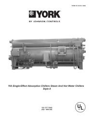
Dimensions - EnglishAll dimensions in English unless otherwise noted32JOHNSON CONTROLS
FORM 150.68-EG1 (1109)All dimensions in English unless otherwise notedUNIT DIMENSIONS60 HZ <strong>Model</strong> <strong>YCUL</strong>0045EE <strong>YCUL</strong>0051EE <strong>YCUL</strong>0055EE <strong>YCUL</strong>0065EE <strong>YCUL</strong>0072EEL<strong>eng</strong>th L 144.8 144.8 148.8 148.8 153.6Width W 90.6 90.6 90.6 90.6 90.6Height H 47.8 47.8 62.6 62.6 62.6ConnectionSizesSystem 1DimmensionsSystem 2DimmensionsIsolatorLocationDimensionsRigging HoleLocationsUnit COGFP 13.6 13.6 28.5 28.5 28.5Suction In 1 2.1 2.1 2.1 2.1 2.3Suction In 2 2.1Liquid Out 1 / 2 1.1 1.1 1.1 1.1 1.1Suction In 48.7 48.7 52.7 44.4 53.7Liquid Out 72.9 72.9 85.1 85.1 77.6Suction In 41.6 41.6 35.1 35.1 33.3Liquid Out 17.3 17.3 14.1 14.1 15D1 19.6 19.7 24 9.7 6.8D2 6.4 6.4 9.1 9.1 5.3D3 13.8 13.8 9.2D4I1 9.8 9.8 9.8 9.8 9.8I2 135 135 135 135 143.8I3I4I5I6I7I8A 1.1 1.1 1.1 1.1 1.1B 89.5 89.5 89.5 89.5 89.5R1 15.1 15.1 15.1 15.1 15.1R2 130.9 130.9 130.9 130.8 137.6R3R4X 59.6 59.2 61.9 61.5 59.7Y 43.6 43.5 42.2 42.2 44.9JOHNSON CONTROLS 33
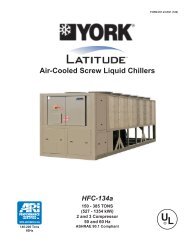
Dimensions - SIAll dimensions in SI unless otherwise noted34JOHNSON CONTROLS
FORM 150.68-EG1 (1109)All dimensions in SI unless otherwise noted50 HZ <strong>Model</strong> <strong>YCUL</strong>0045EE <strong>YCUL</strong>0051EE <strong>YCUL</strong>0055EE <strong>YCUL</strong>0065EE <strong>YCUL</strong>0072EEL<strong>eng</strong>th L 3677.9 3677.9 3779.5 3779.5 3901.4Width W 2301.2 2301.2 2301.2 2301.2 2301.2Height H 1214.1 1214.1 1590.0 1590.0 1590.0ConnectionSizesSystem 1DimensionsSystem 2DimensionsIsolatorLocationDimensionsRigging HoleLocationsUnit COGFP 345.4 345.4 723.9 723.9 723.9Suction In 1 53.3 53.3 53.3 53.3 58.4Suction In 2 53.3Liquid Out 1 / 2 27.9 27.9 27.9 27.9 27.9Suction In 1237.0 1237.0 1338.6 1127.8 1364.0Liquid Out 1851.7 1851.7 2161.5 2161.5 1971.0Suction In 1056.6 1056.6 891.5 891.5 845.8Liquid Out 439.4 439.4 358.1 358.1 381.0D1 497.8 500.4 609.6 246.4 172.7D2 162.6 162.6 231.1 231.1 134.6D3 350.5 350.5 233.7D4I1 248.9 248.9 248.9 248.9 248.9I2 3429.0 3429.0 3429.0 3429.0 3652.5I3I4I5I6I7I8A 27.9 27.9 27.9 27.9 27.9B 2273.2 2273.2 2273.2 2273.2 2273.2R1 383.5 383.5 383.5 383.5 383.5R2 3324.9 3324.9 3324.9 3322.3 3495.0R3R4X 1513.8 1503.7 1572.3 1562.1 1516.4Y 1107.4 1104.9 1071.9 1071.9 1140.5JOHNSON CONTROLS 35
Isolator SelectionsONE INCH DEFLECTION SPRING ISOLATOR CROSS-REFERENCECPX-X-Mount TypeDimension Data (Inches)W D L B C T HCP1 3 5/8 7–3/4 6–1/2 4–3/4 ½ 5–5/8CP2 3 5/8 10–1/2 9–1/4 7–3/4 9/16 6MODEL NUMBERRATED CAPACITY(LBS.)DEFLECTION RATED(IN)COLOR CODECP1-1D-85 85 1.360 LT. PURPLECP1-1D-120 120 1.200 DK. YELLOWCP1-1D-175 175 1.170 DK. BLUECP1-1D-250 250 1.400 YELLOWCP1-1D-340 340 1.130 REDCP1-1D-510 510 1.020 BLACKCP1-1D-675 675 1.320 DK. PURPLECP1-1D-900 900 1.020 DK. GREENCP1-1D-1200 1200 0.900 GRAYCP1-1D-1360 1360 0.770 WHITECP1-1D-1785N 1785 0.880 GRAY/REDMODEL NUMBERRATED CAPACITY(LBS.)DEFLECTION RATED(IN)COLOR CODECP2-1D-1020 1020 1.020 BLACKCP2-1D-1350 1350 1.320 DK. PURPLECP2-1D-1800 1800 1.020 DK. GREENCP2-1D-2400 2400 0.900 GRAYCP2-1D-2720 2720 0.770 WHITECP2-1D-3570N 3570 0.880 GRAY / RED36JOHNSON CONTROLS
FORM 150.68-EG1 (1109)NEOPRENE ISOLATOR CROSS-REFERENCERD-StyleIsolatorsELASTOMERMount TypeDimension Data (inches)L W HF AL AD BT CD DWRD1-WR 3.13 1.75 1.25 2.38 0.34 0.19 5/16-18 UNC X 3/4 1.25RD2-WR 3.88 2.38 1.75 3.00 0.34 0.22 3/8-16 UNC X 1 1.75RD3-WR 5.50 3.38 2.88 4.13 0.56 0.25 1/2-13 UNC X 1 2.50RD4-WR 6.25 4.63 2.75 5.00 0.56 0.38 1/2-13 UNC X 1 3.00MODEL NUMBERRATEDRATED RATEDRATEDCAPACITYDURO (± 5) MODEL NUMBER CAPACITY DEFLECTIONDEFLECTION [IN][LBS][LBS][IN]DURO (± 5)RD2-Light Blue-WR 35 0.4 30 RD3-Brown-WR 250 0.5 40RD2-Brown-WR 45 0.4 40 RD3-Brick Red-WR 525 0.5 50RD2-Brick Red-WR 70 0.4 50 RD3-Lime-WR 750 0.5 60RD 2-Lime-WR 120 0.4 60 RD3-Charcoal-WR 1100 0.5 70MODEL NUMBERRATEDRATEDCAPACITYDURO (± 5)RATEDDEFLECTION [IN]RATED[LBS]MODEL NUMBER CAPACITYDEFLECTION [IN][LBS]DURO (± 5)RD2-Light Blue-WR 135 0.5 30RD2-Brown-WR 170 0.5 40 RD4-Brown-WR 1500 0.5 40RD2-Brick Red-WR 240 0.5 50 RD4-Brick Red-WR 2250 0.5 50RD 2-Lime-WR 380 0.5 60 RD4-Lime-WR 3000 0.5 60RD2 Charcoal-WR 550 0.5 70 RD4-Charcoal-WR 4000 0.5 70JOHNSON CONTROLS 37
Isolator Details - continuedTWO INCH DEFLECTION, SEISMIC SPRING ISOLATOR CROSS-REFERENCEY2RS1-1/8”5/8” 2-3/4”2-3/4”3/8” GAP3/4”TYP. (4)8P43/4”7/8”44STOP &8-3/8”OPER.HEIGHT8MODEL Y2RSI-2D SEISMICALLY RESTRAINED VIBRATION ISOLATOR FOR 2" DEFLECTIONRATED DEFLECTION SPRING RATESEISMIC MOUNT SIZE RATED LOAD (LBS) SOLID LOAD (LBS) COLOR CODE(IN)(LBS/IN)ALLOWABLE GRATING HORIZONTALY2RSI-2D-150 150 2.4 62 234 WHITE 34.7Y2RSI-2D-320 320 2.3 140 490 YELLOW 16.3Y2RSI-2D-460 460 2.3 200 688 GREEN 11.3Y2RSI-2D-710 710 2.2 330 1072 DK BROWN 7.3Y2RSI-2D-870 870 1.9 460 1312 RED 6Y2RSI-2D-1200N 1200 1.9 638 1818 RED/BLACK 4.3Y2RSI-2D-1450 1450 1.8 900 2450 TAN 3.6Y2RSI-2D-1690 1690 1.7 1140 2892 PINK 3.1Y2RSI-2D-2000N 2000 1.7 1318 3342 PINK/BLACK 2.6Y2RSI-2D-2640N 2640 1.5 1854 4283 PINK/GRAY 2Y2RSI-2D-2870N 3080 1.5 2004 4629 PINK/GRAY/ORANGE 1.7Y2RSI-2D-3280N 3740 1.8 2134 4930PINK/GRAY/DKBROWN1.438JOHNSON CONTROLS
Electrical Data - 50 & 60HzFORM 150.68-EG1 (1109)<strong>YCUL</strong>0045 - <strong>YCUL</strong>0072WIRING WITHOUT PUMPCHILLERMODELYCAL00450051005500650072VOLTHZMINIMUMCIRCUITAMPSMCAMIN N/FDISC SWMDSWMIN DUALELEMFUSEMAX DUALELEM FUSEMAX CBSYSTEM # 1 SYSTEM # 2COMPR 1 COMPR 2 FAN COMPR 1 COMPR 2 FANRLA LRA RLA LRA QTY FLA LRA RLA LRA RLA LRA QTY FLA LRA200 60 224 250 250 250 45.4 250 45.4 250 2 7.6 30.9 45.4 250 45.4 250 2 7.6 30.9230 60 209 250 225 250 42.0 250 42.0 250 2 7.4 37.0 42.0 250 42.0 250 2 7.4 37.0380 60 121 150 150 150 24.2 155 24.2 155 2 4.5 22.3 24.2 155 24.2 155 2 4.5 22.3400 50 102 150 110 110 20.0 125 20.0 125 2 4.0 19.0 20.0 125 20.0 125 2 4.0 19.0460 60 99 150 110 110 20.0 125 20.0 125 2 3.4 17.2 20.0 125 20.0 125 2 3.4 17.2575 60 80 100 90 90 16.0 100 16.0 100 2 2.9 14.6 16.0 100 16.0 100 2 2.9 14.6400 50 102 150 110 110 20.0 125 20.0 125 2 4.0 19.0 20.0 125 20.0 125 2 4.0 19.0200 60 228 250 250 250 47.0 250 47.0 250 2 7.6 30.9 45.4 250 45.4 250 2 7.6 30.9230 60 212 250 225 250 43.5 250 43.5 250 2 7.4 37.0 42.0 250 42.0 250 2 7.4 37.0380 60 123 150 150 150 25.1 155 25.1 155 2 4.5 22.3 24.2 155 24.2 155 2 4.5 22.3400 50 103 150 110 110 20.7 125 20.7 125 2 4.0 19.0 20.0 125 20.0 125 2 4.0 19.0460 60 101 150 110 110 20.7 125 20.7 125 2 3.4 17.2 20.0 125 20.0 125 2 3.4 17.2575 60 81 100 90 90 16.6 100 16.6 100 2 2.9 14.6 16.0 100 16.0 100 2 2.9 14.6400 50 103 150 110 110 20.7 125 20.7 125 2 4.0 19.0 20.0 125 20.0 125 2 4.0 19.0200 60 248 400 300 300 51.3 300 51.3 300 2 7.6 44.0 51.3 300 51.3 300 2 7.6 44.0230 60 248 400 300 300 51.3 300 51.3 300 2 7.4 19.1 51.3 300 51.3 300 2 7.4 19.1380 60 132 150 150 150 26.9 139 26.9 139 2 4.5 23.1 26.9 139 26.9 139 2 4.5 23.1460 60 114 150 125 125 23.1 150 23.1 150 2 4.0 19.0 23.1 150 23.1 150 2 4.0 19.0575 60 96 150 110 110 19.9 109 19.9 109 2 2.9 15.3 19.9 109 19.9 109 2 2.9 15.3400 50 106 150 125 125 21.8 140 21.8 140 2 3.4 17.5 21.8 140 21.8 140 2 3.4 17.5200 60 268 400 300 300 55.8 425 55.8 425 2 7.6 44.0 55.8 425 55.8 425 2 7.6 44.0230 60 267 400 300 300 55.8 425 55.8 425 2 7.4 19.1 55.8 425 55.8 425 2 7.4 19.1380 60 171 200 200 200 36.0 239 36.0 239 2 4.5 23.1 36.0 239 36.0 239 2 4.5 23.1460 60 130 150 150 150 26.9 187 26.9 187 2 4.0 19.0 26.9 187 26.9 187 2 4.0 19.0575 60 112 150 125 125 23.7 148 23.7 148 2 2.9 15.3 23.7 148 23.7 148 2 2.9 15.3400 50 114 150 125 125 23.7 198 23.7 198 2 3.4 17.5 23.7 198 23.7 198 2 3.4 17.5200 60 324 400 350 400 76.9 505 76.9 505 2 7.6 30.9 59.9 425 59.9 425 2 7.6 30.9230 60 301 400 350 350 71.2 505 71.2 505 2 7.4 37.0 55.5 425 55.5 425 2 7.4 37.0380 60 175 200 200 200 41.1 280 41.1 280 2 4.5 22.3 32.0 239 32.0 239 2 4.5 22.3400 50 146 200 175 175 33.9 225 33.9 225 2 4.0 19.0 26.4 198 26.4 198 2 4.0 19.0460 60 143 200 175 175 33.9 225 33.9 225 2 3.4 17.2 26.4 187 26.4 187 2 3.4 17.2575 60 115 150 125 125 27.1 180 27.1 180 2 2.9 14.6 21.1 148 21.1 148 2 2.9 14.6400 50 146 200 175 175 33.9 225 33.9 225 2 4.0 19.0 26.4 198 26.4 198 2 4.0 19.0See Notes on page 35.JOHNSON CONTROLS 39
Electrical Data - 50 & 60Hz - continuedUNIT VOLTAGEMODELS w/oCONTROL TRANSMODELS w/CONTROL TRANSUNIT VOLTAGECONTROL POWER115-1-60/50MCAOVER CURRENT PROTECTION, SEENOTE BMINMAXNF DISC Sw15A 10A 15A 30 A / 240V-17 200-1-60 15A 10A 15A 30 A / 240V-28 230-1-60 15A 10A 15A 30 A / 240V-40 380-1-60 15A 10A 15A 30 A / 480V-46 460-1-60 15A 10A 15A 30 A / 480V-50 380/415-1-50 15A 10A 15A 30A / 415V-58 575-1-60 15A 10A 15A 30 A / 600VA. Minimum #14 AWG, 75°C, Copper Re<strong>com</strong>mendedB. Minimum and Maximum Over Current Protection, Dual Element Fuse or Circuit BreakerVOLTAGE RANGEVOLTAGE CODE UNIT POWER MIN. MAX.-17 200-3-60 180 220-28 230-3-60 207 253-40 380-415-3-60 342 440-46 460-3-60 414 506-50 380-415-3-50 342 440-58 575-3-60 517 633LEGENDACRLINE ACROSS THE LINE STARTC.B.CIRCUIT BREAKERD.E.DUAL ELEMENT FUSEDISC SWDISCONNECT SWITCHFACT MOUNT CBFACTORY MOUNTED CIRCUIT BREAKERFLAFULL LOAD AMPSHZHERTZMAXMAXIMUMMCAMINIMUM CIRCUIT AMPACITYMINMINIMUMMINNF MINIMUM NON FUSEDRLARATED LOAD AMPSS.P. WIRESINGLE POINT WIRINGUNIT MTD SERV SW UNIT MOUNTED SERVICE (NON-FUSED DISCONNECT SWITCH)LRALOCKED ROTOR AMPS40JOHNSON CONTROLS
Electrical NotesFORM 150.68-EG1 (1109)NOTES:1. Minimum Circuit Ampacity (MCA) is based on 125% of the rated load amps for the largest motor plus 100% of therated load amps for all other loads included in the circuit, per N.E.C. Article 43024. If the optional Factory MountedControl Transformer is provided, add the following MCA values to the electrical tables for the system providingpower to the transformer: 17, add 2.5 amps; 28, add 2.3 amps; 40, add 1.5 amps, 46, add 1.3 amps; 58, add 1amps.2. The minimum re<strong>com</strong>mended disconnect switch is based on 115% of the rated load amps for all loads included inthe circuit, per N.E.C. Article 440.3. Minimum fuse size is based upon 150% of the rated load amps for the largest motor plus 100% of the rated loadamps for all other loads included in the circuit to avoid nuisance trips at startup due to lock rotor amps. It is notre<strong>com</strong>mended in applications where brown outs, frequent starting and stopping of the unit, and/or operation atambient temperatures in excess of 95ºF (35ºC) is anticipated.4. Maximum fuse size is based upon 225% of the rated load amps for the largest motor plus 100% of the rated loadamps for all other loads included in the circuit, per N.E.C. Article 440-22.5. Circuit breakers must be UL listed and CSA certified and maximum size is based on 225% of the rated load ampsfor the largest motor plus 100% of the rated load amps for all other loads included in the circuit. Otherwise, anHACRtype circuit breakers must be used. Maximum HACR circuit breaker rating is based on 225% of the ratedload amps for the largest motor plus 100% of the rated load amps for all other loads included in the circuit.6. The “INCOMING WIRE RANGE” is the minimum and maximum wire size that can be ac<strong>com</strong>modated by the unitwiring lugs. The (2) preceding the wire range indicates the number of termination points available per phase of thewire range specified. Actual wire size and number of wires per phase must be determined based on the NationalElectrical Code, using copper connectors only. Field wiring must also <strong>com</strong>ply with local codes.7. A ground lug is provided for each <strong>com</strong>pressor system to ac<strong>com</strong>modate a field grounding conductor per N.E.C.Table 25095. A control circuit grounding lug is also supplied.8. The supplied disconnect is a “Disconnecting Means” as defined in the N.E.C. 100, and is intended for isolating theunit for the available power supply to perform maintenance and troubleshooting. This disconnect is not intended tobe a Load Break Device.9. Field Wiring by others which <strong>com</strong>plies to the National Electrical Code & Local Codes.JOHNSON CONTROLS 41
Circuit Breaker CalculationsMax Dual Elem Fuse Max CB (MOP)= 2.25 x Current of largest motor + ∑ (remaining FLAs or RLAs)For this name plate the formula below was used:= 2.25 * RLACpr1 + RLACpr2 + RLACpr3 + Qty* RLAFans + 0.49 + FLAPumpThis formula will calculate the ACTUAL MOP but a table is referenced to provide the appropriate MOP.ACTUALColumnAMINIMUMColumnB*MAXIMUMColumnC0 15 015 20 1520 25 2025 30 2530 35 3035 40 3540 45 4045 50 4550 60 5060 70 6070 80 7080 90 8090 100 90100 110 100110 125 110125 150 125150 175 150175 200 175200 225 200225 250 225250 300 250300 350 300350 400 350(*Note: Column B is used if one were calculatingthe Minimum Dual Elem Fuse which is not relevantto this exercise.)Using an approximate match, look up the value ofthe calculated ACTUAL MOP in Column A. Find thelargest value i.e. less than or equal to the valuein Column A. Once found, the value in Column Cwhich shares the same row is the valued USED inthe system. e.g. e.g. Using the same example thatwas used to calculate the MCA, calculate theMOP:Ans. ACTUAL = 2.25*20.4 + 20.4 + 0 + 2*2.6 + 5.29= 45.9 + 30.89 = 76.79Comparingagainst values in Column A: 70 < 76.79 < 80,therefore the USED MOP found in Column C is 70.42JOHNSON CONTROLS
Application DataFORM 150.68-EG1 (1109)uNiT LOCATiONThe <strong>YCUL</strong> Condensing Units are designed for outdoor installation.When selecting a site for installation, be guidedby the following conditions:1. For outdoor locations of the unit, select a place havingan adequate supply of fresh air for the condenser.2. Avoid locations beneath windows or betweenstructures where normal operating sounds may beobjectionable.3. Installation sites may be either on a roof, or at groundlevel. (See FOUNDATION, below.)4. The condenser fans are the propeller-type, and are notre<strong>com</strong>mended for use with duct work in the condenserair stream.5. When it is desirable to surround the unit(s), it isre<strong>com</strong>mended that the screening be able to pass therequired chiller CFM without exceeding 0.1” of waterexternal static pressure.6. Protection against corrosive environments is availableby supplying the units with either copper fin, curedphenolic, or epoxy coating on the condenser coils.The phenolic or epoxy coils should be offered withany units being installed at the seashore or wheresalt spray may hit the unit.In installations where winter operation is intended andsnow accumulations are expected, additional height mustbe provided to ensure normal condenser air flow.Re<strong>com</strong>mended clearances for units are given in DIMEn-SION DRAWINGS. When the available space is less,the unit(s) must be equipped with the discharge pressuretransducer option to permit high pressure unloading in theevent that air recirculation were to occur.FOuNdATiONThe unit should be mounted on a flat and level foundation,ground or roof, capable of supporting the entire operatingweight of the equipment. Operating weights are given inthe PHYSICAL DATA tables.Roof Locations – Choose a spot with adequate structuralstr<strong>eng</strong>th to safely support the entire weight of the unit andservice personnel. Care must be taken not to damagethe roof during installation. If the roof is “bonded”, consultthe building contractor or architect for special installationrequirements. Roof installations should incorporate theuse of spring-type isolators to minimize the transmissionof vibration into the building structure.Ground Level Installations – It is important that the unitsbe installed on a substantial base that will not settle, causingstrain on the refrigerant lines and resulting in possibleleaks. A one-piece concrete slab with footers extendingbelow the frost line is highly re<strong>com</strong>mended, particularly inareas where winters are long and very cold. Additionally,the slab should not be tied to the main building foundationas noises will telegraph.Mounting holes (11/16” diameter) are provided in the steelchannel for bolting the unit to its foundation. See DIMEN-SION DRAWINGS.For ground level installations, precautions should be takento protect the unit from tampering by or injury to unauthorizedpersons. Screws on access panels will preventcasual tampering; however, further safety precautions,such as unit enclosure options, a fenced-in enclosure, orlocking devices on the panels may be advisable. Checklocal authorities for safety regulations.REFRiGERANT PiPiNGWhen sizing refrigerant pipe for split system air conditioning,consideration must be given to the: (1) Suction linepressure drop due to friction, (2) Liquid line pressure dropdue to friction, (3) Suction line velocity for oil return, and(4) Liquid line pressure drop due to vertical rise. Refer toDESIGN PARAMETERS for friction losses for both thesuction and liquid lines for the condensing unit.On a system where the evaporator blower is located belowthe condensing unit, the suction line must be sized forboth pressure drop and oil return.When the condensing unit is located below the evaporatorblower, the liquid line must be designed for pressuredrop due to friction loss and vertical rise. If the pressuredrop due to vertical rise and friction loss exceeds 30 psig(2.1 barg), some refrigerant will flash before it reachesthe thermal expansion valve.All horizontal suction lines should be pitched at least 1/4inch (6 mm) per foot in the direction of the refrigerant flowto aid the return of oil to the <strong>com</strong>pressor. All suction lineswith a vertical rise exceeding 3 feet (1 m) should have a‘P’ trap at the bottom and the top to facilitate oil return.Suction lines with a vertical rise exceeding 25 feet (7.6 m)should be trapped every 15 feet (4.6 m) to provide drainpoints for the oil when the circuit is deactivated. Whenthe circuit is reactivated, oil will return to the <strong>com</strong>pressormore quickly and in smaller slugs.For more details, refer to ASHRAE Refrigeration Handbook,System Practices for Halocarbon Refrigerants.JOHNSON CONTROLS 43
Guide SpecificationsPART 1 – GENERAL1.01 SCOPEA. The requirements of the General Conditions, SupplementaryConditions, Division 1, and Drawings applyto all Work herein.B. Provide Microprocessor controlled, multiple-scroll<strong>com</strong>pressor, air-cooled, condensing units of thescheduled capacities as shown and indicated on theDrawings, including but not limited to:1. Condensing Unit package2. Electrical power and control connections3. DX Central Station <strong>Air</strong> Handling connections1.02 QUALITY ASSURANCEA. Products shall be Designed, Tested, and installed in<strong>com</strong>pliance with applicable sections of the followingStandards and Codes:1. ANSI/ASHRAE Standard 15 – Safety Code forMechanical Refrigeration2. ASHRAE 90.1 - Energy efficiency <strong>com</strong>pliance.3. ANSI/NFPA Standard 70 – National ElectricalCode (N.E.C.).4. Conform to Intertek Testing Services, formerlyETL, for construction of condensing units andprovide E.T.L./c E.T.L. Listing label.5. Manufactured in facility registered to ISO 9002.B. Factory Test: Condensing Unit shall be pressuretested, evacuated and given a nitrogen holdingcharge and an initial oil charge, and shall be factoryoperational run tested to assure each control deviceoperates properly.C. Warranty: Manufacturer shall Warrant all equipmentand material of its manufacture against defects inworkmanship and material for a period of one yearfrom date of initial start-up or eighteen (18) monthsfrom date of shipment, whichever occurs first.1.03 DELIVERY AND HANDLINGA. Unit shall be delivered to job site fully assembled, andgiven nitrogen holding charge and a full oil charge bythe Manufacturer. (R-410A refrigerant supplied byothers).B. Unit shall be stored and handled per Manufacturer’sinstructions.PART 2 - PRODUCTS2.01 CONDENSING UNITS MATERIALS AND COMO-NENTSA. General: Install and <strong>com</strong>mission, as shown on theschedules and plans, factory assembled, charged,and tested air cooled scroll <strong>com</strong>pressor condensingunit as specified herein. Condensing Unit shall bedesigned, selected, and constructed using a refrigerantwith Flammability rating of “1”, as defined byANSI/ASHRAE STANDARD - 34 Number Designationand Safety Classification of Refrigerants. CondensingUnit shall include, but is not limited to: not less thantwo refrigerant circuits, scroll <strong>com</strong>pressors, air-cooledcondenser, refrigerant, lubrication system, interconnectingwiring, safety and operating controls includingcapacity controller, control center, motor starting<strong>com</strong>ponents, and special features as specified hereinor required for safe, automatic operation.B. Cabinet: External structural members shall be constructedof heavy gauge, galvanized steel coated withbaked on powder paint which, when subject to ASTMB117, 1000 hour, 5% salt spray test, yields minimumASTM 1654 rating of “6”.2.02 COMPRESSORSA. <strong>Compressor</strong>s: Shall be hermetic, scroll-type, including:1. Compliant design for axial and radial sealing.2. Refrigerant flow through the <strong>com</strong>pressor with100% suction cooled motor.3. Large suction side free volume and oil sump toprovide liquid handling capability.4. <strong>Compressor</strong> crankcase heaters to provide extraliquid migration protection.5. Annular discharge check valve and reverse ventassembly to provide low pressure drop, silentshutdown and reverse rotation protection.6. Initial Oil charge.7. Oil Level sightglass.8. Vibration isolator mounts for <strong>com</strong>pressors.9. Brazed-type connections for fully hermetic refrigerantcircuits.2.03 REFRIGERANT CIRCUITTwo independent refrigerant circuits will be furnished oneach unit. All unit piping will be copper, with brazed joints.The liquid line will include a field connection shutoff valvewith charging port located on each condenser circuit. Suctionline connections are provided on each refrigerationcircuit. Filter drier and sight glass are shipped loose forfield installation on each refrigerant circuit. All expansionvalves and liquid line solenoid valves and refrigerant fieldpiping are supplied by others.2.04 HEAT EXCHANGERSA. <strong>Air</strong> <strong>Cooled</strong> Condenser:44JOHNSON CONTROLS
FORM 150.68-EG1 (1109)1. Coils: Internally enhanced, seamless coppertubes, mechanically expanded into aluminumalloy fins with full height collars. Subcooling coilan integral part of condenser. Design workingpressure shall be 650 psig (45 barg).2. Fans: Shall be dynamically and statically balanced,direct drive, corrosion resistant glass fiberreinforced <strong>com</strong>posite blades molded into lownoise, full airfoil cross section, providing verticalair discharge from extended orifices for efficiencyand low sound. Each fan in its own <strong>com</strong>partmentto prevent cross flow during fan cycling. Guardsof heavy gauge PVC (polyvinyl chloride) coatedsteel.3. Fan Motors: High efficiency, direct drive, 6 pole,3 phase, insulation class “F”, current-protected,Totally Enclosed <strong>Air</strong>-Over (TEAO), rigid mounted,with double sealed, permanently lubricated, ballbearings.2.05 CONTROLSA. General: Automatic start, stop, operating, and protectionsequences across the range of scheduledconditions and transients.B. Microprocessor Enclosure: Rain and dust tight NEMA3R/12 (IP55) powder painted steel cabinet withhinged, latched, and gasket sealed door.C. Microprocessor Control Center:1. Condensing Unit control is set for Discharge <strong>Air</strong>Temperature Control2. Automatic control of <strong>com</strong>pressor start/stop, anticoincidenceand anti-recycle timers, automaticpump-down shut-down, condenser fans, unitalarm contacts, and condensing unit operationfrom 0°F to 125°F (-18°C to 52°C) ambient. Automaticreset to normal chiller operation after powerfailure.3. Software stored in non-volatile memory, withprogrammed set-points retained in lithium battery-backedreal time clock (RTC) memory forminimum 5 years.4. Forty character liquid crystal display, descriptionsin English (or Spanish, French, Italian, orGerman), numeric data in English (or Metric)units. Sealed keypad with sections for Setpoints,Display/Print, Entry, Unit Options & clock, andOn/Off Switch.5. Programmable Set-points (within Manufacturerlimits): display language; suction pressure settingand control range, remote reset temperaturerange, set daily schedule/holiday for start/stop,manual override for servicing, low and highambient cutouts, number of <strong>com</strong>pressors, lowsuction pressure cutout, high discharge pressurecutout, anti-recycle timer (<strong>com</strong>pressor start cycletime), and anticoincident timer (delay <strong>com</strong>pressorstarts).6. Display Data: Suction temperatures (optional),low ambient temperature cutout setting, outdoorair temperature, English or metric data, suctionpressure cutout setting, each system suction pressure,discharge pressure (optional), discharge airreset via Building Automation System (by others)via a 4-20milliamp or 0-10 VDC input with optionalBAS interface, anti-recycle timer status for eachsystem, anti-coincident system start timer condition,<strong>com</strong>pressor run status, no cooling loadcondition, day, date and time, daily start/stoptimes, holiday status, automatic or manual systemlead/lag control (when controlling based onDischarge <strong>Air</strong> Temperature only), automatic lead/lag of <strong>com</strong>pressors within a system, <strong>com</strong>pressorstarts/operating hours (each), status of hot gasvalves, and fan operation, run permissive status,number of <strong>com</strong>pressors running, liquid solenoidvalve status, load & unload timer status.7. System Safeties: Shall cause individual <strong>com</strong>pressorsystems to perform auto shut down; manualreset required after the third trip in 90 minutes.Includes: high discharge pressure, low suctionpressure, high pressure switch, and motor protector.<strong>Compressor</strong> motor protector shall protectagainst damage due to high input current orthermal overload of windings.8. Unit Safeties: Shall be automatic reset and cause<strong>com</strong>pressors to shut down if low ambient, or undervoltage.9. Alarm Contacts: Low ambient, low voltage, lowbattery, and (per <strong>com</strong>pressor circuit): high dischargepressure, and low suction pressure.10. High Ambient Control: Permits unit operationabove 115°F (46°C) ambient.D. Manufacturer shall provide any controls not listedabove, necessary for automatic condensing unitoperation. Mechanical Contractor shall provide fieldcontrol wiring necessary to interface sensors to thecondensing unit control system.2.06 POWER CONNECTION AND DISTRIBUTIONA. Power Panels:1. NEMA 3R/12 (IP55) rain/dust tight, powderpainted steel cabinets with hinged, latched, andJOHNSON CONTROLS 45
Guide Specifications – continuedgasket sealed outer doors. Provide main powerconnection(s), control power connections, <strong>com</strong>pressorand fan motor start contactors, currentoverloads, and factory wiring.2. Power supply shall enter unit at a single location,be 3 phase of scheduled voltage, and connectto individual terminal blocks per <strong>com</strong>pressor.Separate disconnecting means and/or externalbranch circuit protection (by Contractor) requiredper applicable local or national codes.B. Exposed <strong>com</strong>pressor, control and fan motor powerwiring shall be routed through liquid tight conduit.2.07 ACCESSORIES AND OPTIONSSome accessories and options supercede standard productfeatures. Your YORK representative will be pleasedto provide assistance.A. Microprocessor controlled, Factory installed Acrossthe-Linetype <strong>com</strong>pressor motor starters as standard.B. Outdoor Ambient Temperature Control1. Low Ambient Control: Permits unit operation to0°F (-18°C) ambient. Standard unit controls to32°F (0°C) ambient.C. Power Supply Connections:1. Single Point Power Supply: Single point TerminalBlock for field connection and interconnectingwiring to the <strong>com</strong>pressors. Separate externalprotection must be supplied, by others, in thein<strong>com</strong>ing power wiring, which must <strong>com</strong>ply withthe National Electric Code and/or local codes.2. Single Point: Single point Non-Fused Disconnect(s)and lockable external handle (in <strong>com</strong>pliance withArticle 440-14 of N.E.C.) can be supplied to isolatethe unit power voltage for servicing. Separateexternal fusing must be supplied, by others, in thein <strong>com</strong>ing power wiring, which must <strong>com</strong>ply withthe National Electric Code and/or local codes.3. Single Point Circuit Breaker: Single point TerminalBlock with Circuit Breaker and lockable externalhandle (in <strong>com</strong>pliance with Article 44014 ofN.E.C.) can be supplied to isolate power voltagefor servicing. In<strong>com</strong>ing power wiring must <strong>com</strong>plywith the National Electric Code and/or localcodes.D. Pressure & Temperature Transducers and Sensors1. Discharge Pressure Transducers: Permits unit tosense and display discharge pressure.2. Suction Pressure Transducers: Permits unit tosense and display suction pressure.3. Suction Temperature Sensors: Permits units tosense and display suction temperature.E. Control Power Transformer: Converts unit powervoltage to 120-1-60 or 120-1-50 for 50Hz units (500VA capacity). Factory mounting includes primary- andsecondary-wiring between the transformer and thecontrol panel.F. Motor Current Module: Capable of monitoring <strong>com</strong>pressormotor current. Provides extra protectionagainst <strong>com</strong>pressor reverse rotation, phase-loss andphase imbalance. Options consists of one module perelectrical system. (Factory mounted)G. Power Factor Correction Capacitors: Provided to correctunit <strong>com</strong>pressor factors to a 0.90-0.95.H. Condenser Coil Environmental Protection:1. Pre-Coated: Epoxy coated aluminum fin stock toguard from corrosive agents and insulate againstgalvanic potential. For mild seashore or industriallocations2. Copper Fin: Provide copper fins in lieu of aluminum.3. Post-Coated Dipped: Dipped-cured coating oncondenser coils for seashore and other corrosiveapplications (with the exception of strong alkalis,oxidizers, and wet bromine, chlorine and fluorinein concentrations greater than 100ppm).I. Protective Condensing Unit Panels (Factory or FieldMounted):1. Louvered Panels (condenser coils only): Paintedsteel as per remainder of unit cabinet, over externalcondenser coil faces.2. Wire Panels (full unit): Heavy gauge, welded wiremesh,coated to resist corrosion, to protect condensercoils from incidental damage and restrictunauthorized access to internal <strong>com</strong>ponents.3. Louvered Panels (full unit): Painted steel as perremainder of unit cabinet, to protect condensercoils from incidental damage,visually screeninternal <strong>com</strong>ponents, and prevent unauthorizedaccess to internal <strong>com</strong>ponents.4. Louvered/Wire Panels: Louvered steel panelson external condenser coil faces, painted as perremainder of unit cabinet. Heavy gauge, weldedwire-mesh, coated to resist corrosion, aroundbase of machine to restrict unauthorized access.J. Service Isolation valves: Service suction and discharge(ball type) isolation valves are added to unit46JOHNSON CONTROLS
FORM 150.68-EG1 (1109)per system. This option also includes a system highpressure relief valve in <strong>com</strong>pliance with ASHRAE15.(Factory-mounted.)K. Hot Gas By-Pass: Permits continuous, stable operationat capacities below the minimum step of unloadingto as low as 5% capacity (depending on both theunit & operating conditions) by introducing an artificialload. Hot gas by-pass is installed on only refrigerantsystem #1 on two circuited units.L. Microprocessor Membrane Keypad Graphics on inlieu of Standard English:1. French language.2. German language.3. Spanish language.4. Italian language.M. Chicago Code Relief Valves to meet Chicago Coderequirements.N. Building Automation System (EMS) Reset Interface:Condensing Unit to accept 4 to 20mA, 0 to 10 VDC,input to reset the discharge air temperature.O. Sound Reduction (Factory Mounted):1. Low speed, reduced noise fans2. <strong>Compressor</strong> Acoustic Sound BlanketsP. Vibration Isolation (Field Mounted):1. Neoprene Pad Isolators.2. 1 Inch Deflection Spring Isolators: Level adjustable,spring and cage type isolators for mountingunder the unit base rails.3. 2 Inch Deflection Seismic Isolators: Level adjustable,restrained mounts in rugged welded steelhousing with vertical and horizontal limit stops.Housings shall be designed to withstand a minimum1.0g accelerated force in all directions to 2inches.PART 3 - EXECUTION3.01 INSTALLATIONA. General: Rig and Install in full accordance withManufacturers requirements, Project drawings, andContract documents.B. Location: Locate condensing unit as indicated ondrawings, including cleaning and service maintenanceclearance per Manufacturer instructions. Adjust andlevel condensing unit on support structure.C. Components: Installing Contractor shall provide andinstall all auxiliary devices and accessories for fullyoperational condensing unit.D. Electrical: Coordinate electrical requirements and connectionsfor all power feeds with Electrical Contractor(Division 16).E. Controls: Coordinate all control requirements andconnections with Controls Contractor.F. Finish: Installing Contractor shall paint damaged andabraded factory finish with touch-up paint matchingfactory finish.JOHNSON CONTROLS 47
Printed on recycled paperForm 150.68-EG1 (1109) Supersedes: 150.68-EG1 (1009)© 2008 Johnson Controls, Inc. P.O. Box 423, Milwaukee, WI 53201 Printed in USAwww.johnsoncontrols.<strong>com</strong>