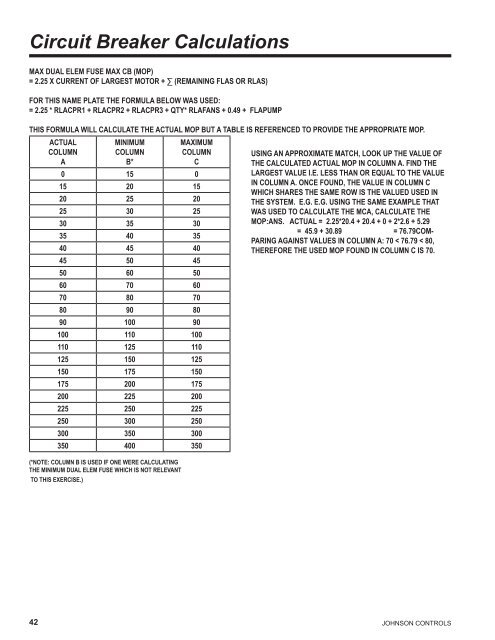
Circuit Breaker CalculationsMax Dual Elem Fuse Max CB (MOP)= 2.25 x Current of largest motor + ∑ (remaining FLAs or RLAs)For this name plate the formula below was used:= 2.25 * RLACpr1 + RLACpr2 + RLACpr3 + Qty* RLAFans + 0.49 + FLAPumpThis formula will calculate the ACTUAL MOP but a table is referenced to provide the appropriate MOP.ACTUALColumnAMINIMUMColumnB*MAXIMUMColumnC0 15 015 20 1520 25 2025 30 2530 35 3035 40 3540 45 4045 50 4550 60 5060 70 6070 80 7080 90 8090 100 90100 110 100110 125 110125 150 125150 175 150175 200 175200 225 200225 250 225250 300 250300 350 300350 400 350(*Note: Column B is used if one were calculatingthe Minimum Dual Elem Fuse which is not relevantto this exercise.)Using an approximate match, look up the value ofthe calculated ACTUAL MOP in Column A. Find thelargest value i.e. less than or equal to the valuein Column A. Once found, the value in Column Cwhich shares the same row is the valued USED inthe system. e.g. e.g. Using the same example thatwas used to calculate the MCA, calculate theMOP:Ans. ACTUAL = 2.25*20.4 + 20.4 + 0 + 2*2.6 + 5.29= 45.9 + 30.89 = 76.79Comparingagainst values in Column A: 70 < 76.79 < 80,therefore the USED MOP found in Column C is 70.42JOHNSON CONTROLS
Application DataFORM 150.68-EG1 (1109)uNiT LOCATiONThe <strong>YCUL</strong> Condensing Units are designed for outdoor installation.When selecting a site for installation, be guidedby the following conditions:1. For outdoor locations of the unit, select a place havingan adequate supply of fresh air for the condenser.2. Avoid locations beneath windows or betweenstructures where normal operating sounds may beobjectionable.3. Installation sites may be either on a roof, or at groundlevel. (See FOUNDATION, below.)4. The condenser fans are the propeller-type, and are notre<strong>com</strong>mended for use with duct work in the condenserair stream.5. When it is desirable to surround the unit(s), it isre<strong>com</strong>mended that the screening be able to pass therequired chiller CFM without exceeding 0.1” of waterexternal static pressure.6. Protection against corrosive environments is availableby supplying the units with either copper fin, curedphenolic, or epoxy coating on the condenser coils.The phenolic or epoxy coils should be offered withany units being installed at the seashore or wheresalt spray may hit the unit.In installations where winter operation is intended andsnow accumulations are expected, additional height mustbe provided to ensure normal condenser air flow.Re<strong>com</strong>mended clearances for units are given in DIMEn-SION DRAWINGS. When the available space is less,the unit(s) must be equipped with the discharge pressuretransducer option to permit high pressure unloading in theevent that air recirculation were to occur.FOuNdATiONThe unit should be mounted on a flat and level foundation,ground or roof, capable of supporting the entire operatingweight of the equipment. Operating weights are given inthe PHYSICAL DATA tables.Roof Locations – Choose a spot with adequate structuralstr<strong>eng</strong>th to safely support the entire weight of the unit andservice personnel. Care must be taken not to damagethe roof during installation. If the roof is “bonded”, consultthe building contractor or architect for special installationrequirements. Roof installations should incorporate theuse of spring-type isolators to minimize the transmissionof vibration into the building structure.Ground Level Installations – It is important that the unitsbe installed on a substantial base that will not settle, causingstrain on the refrigerant lines and resulting in possibleleaks. A one-piece concrete slab with footers extendingbelow the frost line is highly re<strong>com</strong>mended, particularly inareas where winters are long and very cold. Additionally,the slab should not be tied to the main building foundationas noises will telegraph.Mounting holes (11/16” diameter) are provided in the steelchannel for bolting the unit to its foundation. See DIMEN-SION DRAWINGS.For ground level installations, precautions should be takento protect the unit from tampering by or injury to unauthorizedpersons. Screws on access panels will preventcasual tampering; however, further safety precautions,such as unit enclosure options, a fenced-in enclosure, orlocking devices on the panels may be advisable. Checklocal authorities for safety regulations.REFRiGERANT PiPiNGWhen sizing refrigerant pipe for split system air conditioning,consideration must be given to the: (1) Suction linepressure drop due to friction, (2) Liquid line pressure dropdue to friction, (3) Suction line velocity for oil return, and(4) Liquid line pressure drop due to vertical rise. Refer toDESIGN PARAMETERS for friction losses for both thesuction and liquid lines for the condensing unit.On a system where the evaporator blower is located belowthe condensing unit, the suction line must be sized forboth pressure drop and oil return.When the condensing unit is located below the evaporatorblower, the liquid line must be designed for pressuredrop due to friction loss and vertical rise. If the pressuredrop due to vertical rise and friction loss exceeds 30 psig(2.1 barg), some refrigerant will flash before it reachesthe thermal expansion valve.All horizontal suction lines should be pitched at least 1/4inch (6 mm) per foot in the direction of the refrigerant flowto aid the return of oil to the <strong>com</strong>pressor. All suction lineswith a vertical rise exceeding 3 feet (1 m) should have a‘P’ trap at the bottom and the top to facilitate oil return.Suction lines with a vertical rise exceeding 25 feet (7.6 m)should be trapped every 15 feet (4.6 m) to provide drainpoints for the oil when the circuit is deactivated. Whenthe circuit is reactivated, oil will return to the <strong>com</strong>pressormore quickly and in smaller slugs.For more details, refer to ASHRAE Refrigeration Handbook,System Practices for Halocarbon Refrigerants.JOHNSON CONTROLS 43